

PowerTec TS1001 Owner's Manual

Owner’s Manual
QUESTION...
1•877•393•7121
10” TABLE SAW
Model No. TS1001
Visit us on the web at www.southerntechllc.com
You will need this manual for safety instructions, operating procedures, and warranty.
Put it and the original sales invoice in a safe, dry place for future reference.
11-0423
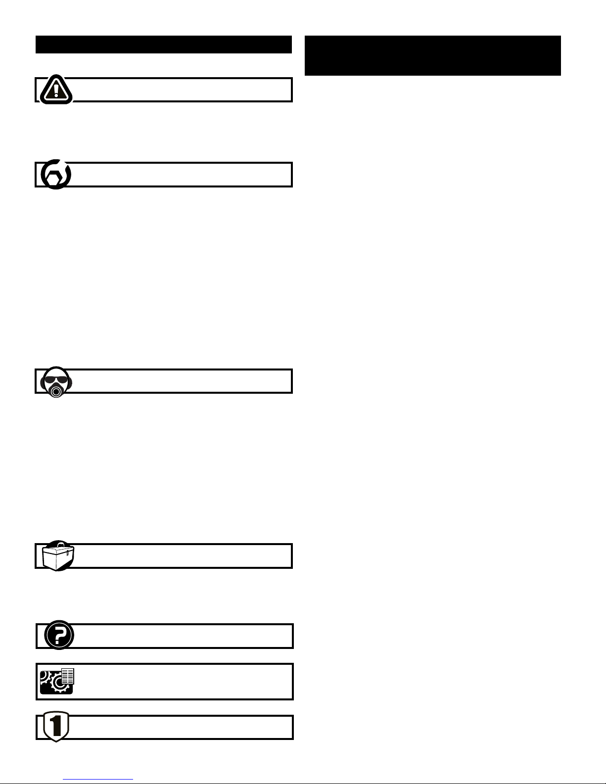
TABLE OF CONTENTS
PRODUCTION
SECTION PAGE
SAFETY RULES 1
Work Preparation
Work Area Preparation
Tool Maintenance
Tool Preparation
ASSEMBLY 2
Unpackaging
Tool Needed
Mount Table Saw
Install the Bracket for the Push Stick
Raise and Lower the Saw Blade
Tilt Saw Blade
Rip Fence
Install and Change the Blade
Blade Guard Assembly
Adjust the saw Blade Guard
Adjust Cutting Angle
Adjust Blade Parallel to the Miter Gauge Slot
Grounding Instructions
Extension Cords
SPECIFICATIONS
Horsepower (Peak HP) . . . . . . . . . . . . . . . . . . . . 2-1/2 HP
Voltage . . . . . . . . . . . . . . . . . . . . . . . . . . . . . . . . . . . . 120
Amp . . . . . . . . . . . . . . . . . . . . . . . . . . . . . . . . . . . . . . . 15
Hertz . . . . . . . . . . . . . . . . . . . . . . . . . . . . . . . . . . . . . . . 60
RPM . . . . . . . . . . . . . . . . . . . . . . . . . . . . . . . . . . . . .5,000
Blade . . . . . . . . . . . . . . . . . 10”-36T Carbide Tipped Blade
Table dimensions . . . . . . . . . . . . . . . . . . . . . . . . 26” x 19”
Table tilts . . . . . . . . . . . . . . . . . . . . . . . . . . . . . . . . 0 to 45°
Maximum Depth of Cut at 90˚ . . . . . . . . . . . . . . . . . . . . .3”
Maximum Depth of Cut at 45˚ . . . . . . . . . . . . . . . . . . . 2.5”
Maximum Depth of Dado . . . . . . . . . . . . . . . . . . . . . . . 1/2”
OPERATION 6
Safety Precautions
On/Off Switch
Overload Protection
Ripping
Bevel Ripping
Crosscutting 90˚ Miter Gauge
Bevel Crosscutting: 0˚ ~ 45˚ Bevel and 90˚ Miter
Angle
Compound Miter Crosscutting: 0˚ ~ 45˚ Blade Bevel
and 0˚ ~ 45˚ Miter Gauge
0˚ ~ 45˚ Miter Angle
MAINTENANCE 9
Cleaning
Lubrication
Keep Tool in Repair
TROUBLESHOOTING 10
PARTS ILLUSTRATION & 12
LIST
WARRANTY 14

SAFETY RULES
1
Some dust created by power sanding, sawing, grinding,
drilling and other construction activities contains chemicals
known to cause cancer, birth defects or other reproductive
harm.
Some examples of these chemicals are:
• Lead from lead-based paints.
• Crystalline silica from bricks and cement and other
masonry products.
• Arsenic and chromium from chemically-treated
lumber.
Your risk from these exposures varies, depending on how
often you do this type of work. To reduce your exposure to
these chemicals: work in a well ventilated area and work
with approved safety equipment. Always wear OSHA/
NIOSH approved, properly fitting face mask or respirator
when using such tools.
WARNING
For your own safety, read all of the rules and precautions
before operating tool.
WARNING
Always follow proper operating procedures as defined
in this manual even if you are familiar with use of this or
similar tools. Remember that being careless for even a
fraction of a second can result in severe personal injury.
WORK PREPARATION
• Wear proper apparel. Do not wear loose clothing,
gloves, neckties, rings, bracelets or other jewelry which
may get caught in moving parts of the tool.
• Wear protective hair covering to contain long hair.
• Wear safety shoes with non-slip soles.
• Wear safety glasses complying with United States
ANSI Z87.1. Everyday glasses have only impact
resistant lenses. They are NOT safety glasses.
• Wear face mask or dust mask if operation is dusty.
• Be alert and think clearly. Never operate power tools
when tired, intoxicated or when taking medications that
cause drowsiness.
WORK AREA PREPARATION
• Keep work area clean. Cluttered work areas invite
accidents.
• Do not use power tools in dangerous environments. Do
not use power tools in damp or wet locations. Do not
expose power tools to rain.
• Work area should be properly lighted.
• Proper electrical receptacle should be available for tool.
Three-prong plug should be plugged directly into
properly grounded, three-prong receptacle.
• Extension cords should have a grounding prong and
the three wires of the extension cord should be of the
correct gauge.
• Keep visitors at a safe distance from work area.
• Keep children out of the work area. Ensure your work
shop is child-proof. Use padlocks, master switches or
remove switch keys to prevent any unintentional use of
power tools.
TOOL MAINTENANCE
• Always unplug tool prior to inspection.
• Consult manual for specific maintaining and adjusting
procedures.
• Keep tool lubricated and clean for a safe operation.
• Remove adjusting tools. Form habit of checking to see
that adjusting tools or accessories are removed before
switching tool on.
• Keep all parts in working order. Check to determine that
guard or other parts will operate properly and perform
their intended function.
• Check for damaged parts. Check for alignment of
moving parts, binding, breakage, mounting and any
other condition that may affect tool’s operation.
• A guard or any other part that is damaged should be
properly repaired or replaced. Do not perform makeshift
repairs.
TOOL OPERATION
• Use the right tool for your job. Do not force your
tool or attachment to do a job for which it was not
designed.
• Disconnect tool when changing sanding sheets/belts.
• Avoid accidental start-up. Make sure that the tool is in
the “OFF” position before plugging in.
• Do not force tool. It will work most efficiently at the rate
for which it was designed. Keep hands away from
moving parts and sanding surfaces.
• Never leave tool running unattended. Turn the power off
and do not leave tool until it comes to a complete stop.
• Do not overreach. Keep proper footing and balance.
• Never stand on tool. Serious injury could occur if tool is
tipped or if sanding surface is unintentionally contacted.
• Know your tool. Learn the tool’s operation, application
and specific limitations before using it.
• Use recommended accessories. Use of improper
accessories may cause risk of injury to persons.
• Handle workpiece correctly. Protect hands from possible
injury.
• Turn tool off if it jams. The motor may jam if too much
pressure is applied on the sanding surface.
• Support workpiece with mitre gauge, belt platen or work
table.
• Maintain 1/16” (1.5 mm) maximum clearance between
table and sanding belt or disc.
CAUTION: Think safety! Safety is a combination of operator common sense and alertness at all times when tool is
being used.
WARNING
Do not attempt to operate tool until it is completely
assembled according to the instructions.
2
ASSEMBLY
UNPACKING
Check for shipping damage. If damage has occurred, a
claim must be filled with carrier. Check for completeness.
Immediately report missing parts to dealer.
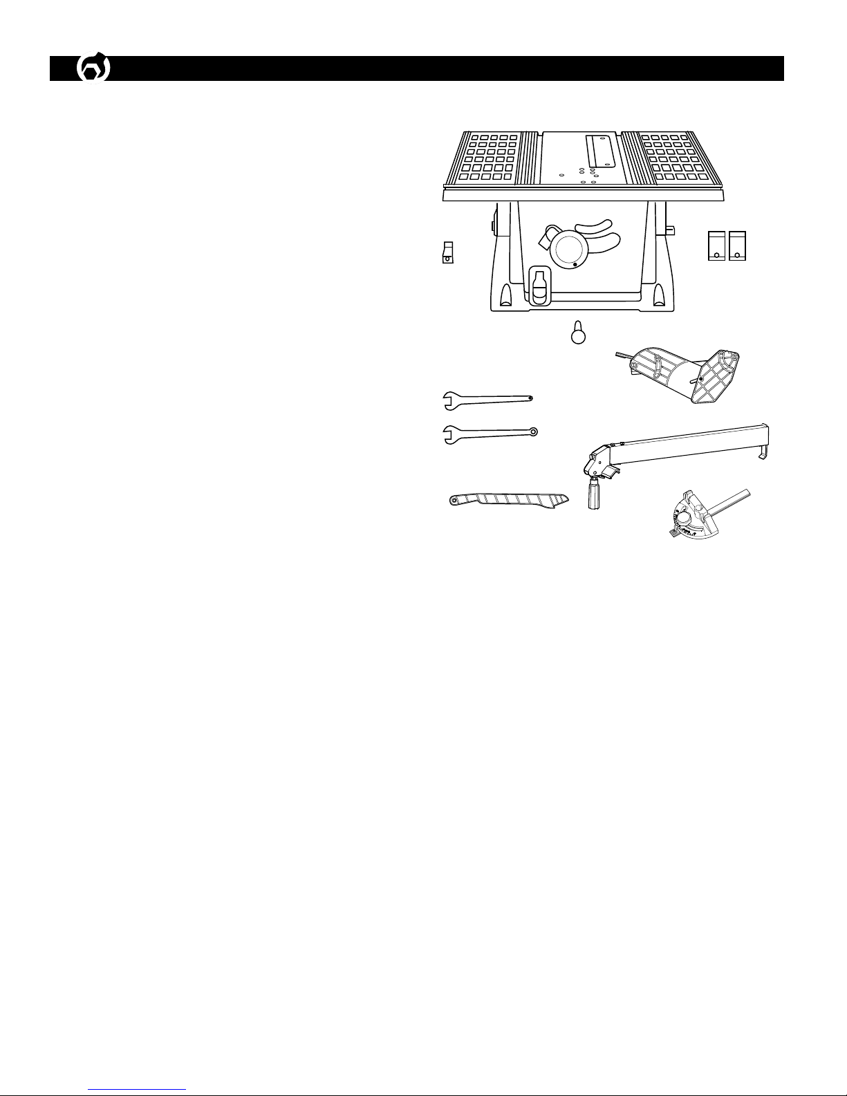
Your table saw is shipped complete in one container.
Carefully unpack the table saw and all loose items from
the shipping container. Figure 1, illustrates the table saw
and all loose parts.
ITEM DESCRIPTION QUANTITY
A Saw Assembly 1
B Plug Clip 1
C Rip Fence/Push Stick Storage Clips 2
D Hand Wheel Grip 1
E Guard/Splitter Assembly 1
F Open-end Wrench 1
G Open-end Wrench 1
H Push Stick 1
I Rip Fence 1
J Mitre Gauge Assembly 1
Figure 1
B
A
C
D
F
G
H
I
E
J
CAUTION: Do not attempt assembly if parts are missing.
Use this manual to order replacement parts.
WARNING
Do not operate this tool until completely assembled. Do
not operate this tool until you have completely read
and understood this manual.
MOUNT TABLE SAW
Refer to figure 2
• The table saw must be installed in a well-lighted area
with correct power supply.
• The table saw can be installed on either a workbench or
a tool stand by using bolts, lock washers, and hex nuts.
• The table saw must be bolted to a firm and level surface.
• There must be enough clearance for the moving
workpiece during operation and enough room for safety
operation of the machine.
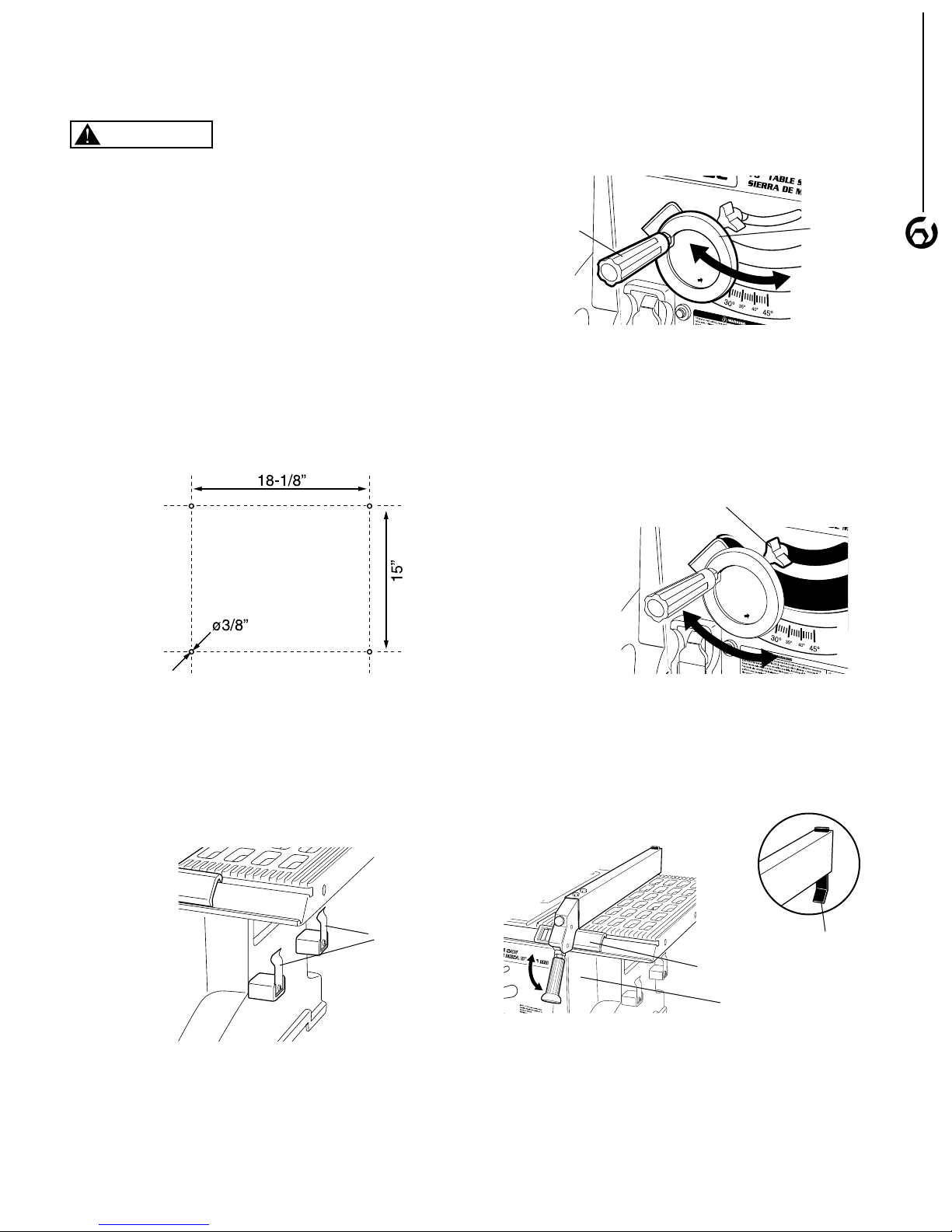
Figure 2 shows the base dimension and mounting holes.
Figure 2
RAISE AND LOWER THE SAW BLADE
Refer to Figure 4
1. Screw the crank handle into the hand wheel.
2. Turn the hand wheel clockwise to lower the blade and
turn the hand wheel counterclockwise to raise the blade.
Figure 4
Hand WheelCrank Handle
TILT SAW BLADE
Refer to Figure 5
1. Loosen blade miter angle lock knob to tilt the saw
blade.
2. Slide the hand wheel without turning it until the blade is
at the desired angle.
3. Tighten the miter angle lock knob.
Figure 5
Miter Angle Lock Knob
ASSEMBLY
3
INSTALL THE BRACKET FOR THE PUSH
STICK
Refer to Figure 3
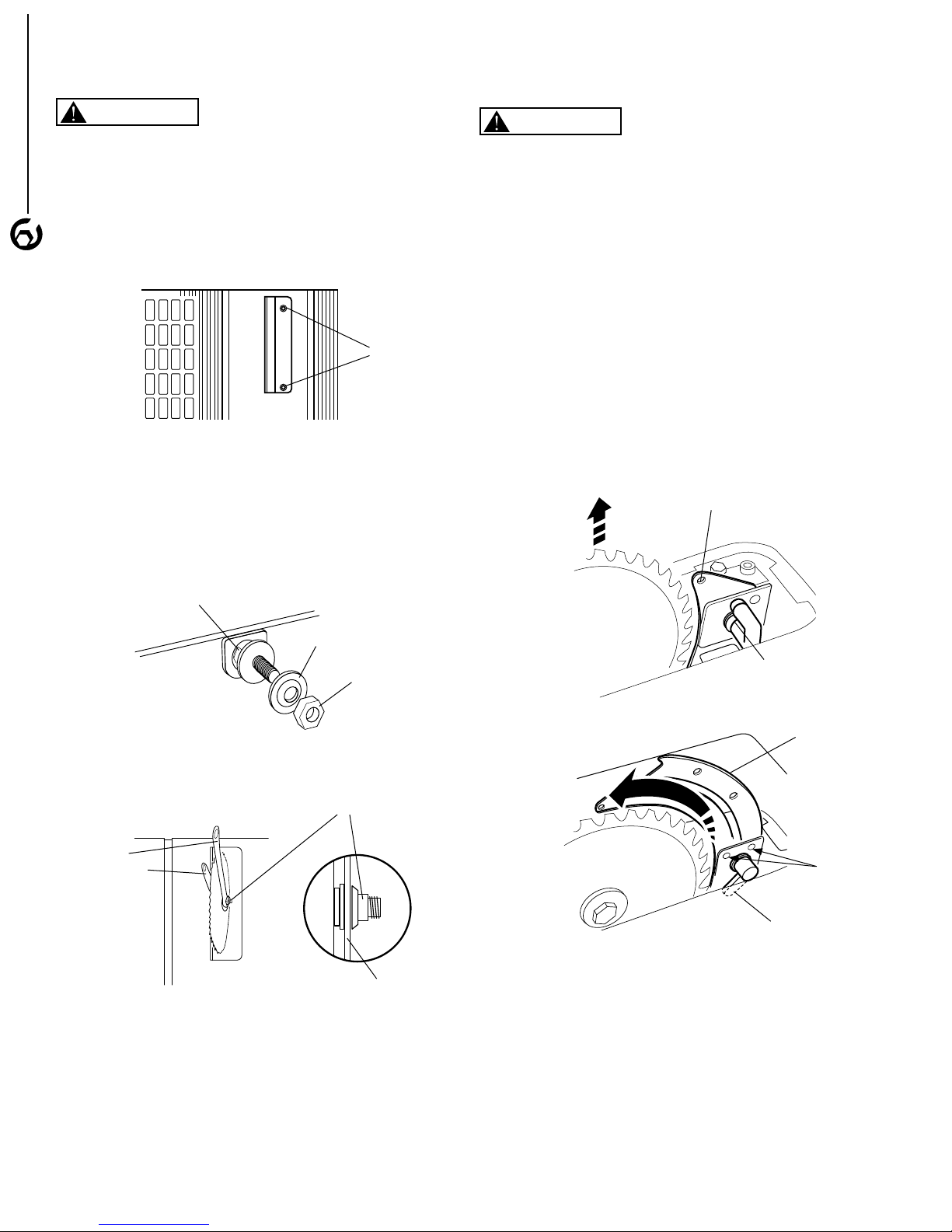
Secure the two brackets to the right-hand side of the saw
using the Phillips screw supplied.
Figure 3
Brackets
RIP FENCE
Refer to figure 6
1. Position the fence on the saw table.
2. Hook the rear steel clamp plate of fence over the back
edge of saw table.
3. Engage the lock head into the front groove of saw table.
Figure 6
Rear Steel Clamp
Lock Head
Fence Handle
4. Lift the fence lock hand and slide the fence to the
desired position. The rip fence is usually operated on
the right hand side of the table.
5. Push down the lock hand to secure the fence position.
6. Rotate knob clockwise to increase fence tension on the
saw table if necessary.
INSTALL AND CHANGE THE BLADE
ASSEMBLY
Refer to Figure 7, 8 and 9
BLADE GUARD ASSEMBLY
Refer to Figure 10
WARNING
Turn the switch to OFF position and disconnect the machine from power source.
CAUTION: Wear gloves while installing and removing the
saw blade
1. Remove the table insert.
2. Raise the blade arbor to the maximum height by turning
4
the blade elevation control wheel counter-clockwise.
Figure 7
Screws
3. Remove the arbor nut and flange.
4. Install the saw blade onto the arbor with the blade teeth
pointing toward the fornt of the saw.
5. Install the flange against the blade and thread the arbor
nut as far as possible by hand. Ensure that the blade is
flush against the inner blade flange.
WARNING
Turn the switch to OFF position and disconnect the
machine from power source.
POSITION THE RIVING KNIFE
1. Remove the table insert.
2. Set the blade to the maximum height and the tilt to zero
degrees on the bevel scale.
3. Rotate the riving knife release lever clockwise, so that it
points upward.
4. Pull riving knife towards release lever to disengage it
from the pins.
5. Slide the riving knife up to its highest position, so that it
is directly over the center of the blade.
6. Align holes in riving knife with pins and lock the release
lever by rotating it counterclockwise. Push/Pull riving
knife to verify that it is locked in place.
7. Replace table insert.
Figure 10
Riving Knife
Figure 8
Blade Arbor
Blade Flange
Arbor Nut
Figure 9
Open-end
Blade Wrench
Saw Blade
6. To tighten the arbor nut, use the open end wrench and
align the wrench jaws on the flats of the flange to keep
the arbor from turning.
7. Place the box and wrench on the arbor nut, and turn
clockwise (to the rear of the table saw).
8. Lightly insert the rear part of the table insert into table,
and pull down its front part in table recess to lock.
Release Lever
Figure 11
Riving Knife
Pin
Release Lever
BLADE GUARD INSTALLATION
Blade guard installation
1. Hold the front of the barrier guard assembly by the
metal “fork” with one hand. Hold the guard release
lever up with the other hand.
2. Lower the rear of guard assembly and slip the cross
bar into the rear notch on top of the riving knife.
3. Lower the front of the guard assembly until the metal
“fork” is parallel with the table.
4. Press down on the guard release lever until you feel
and hear it snap into the locking position. Check that
the guard assembly is securely connected.
 Loading...