

Page 1
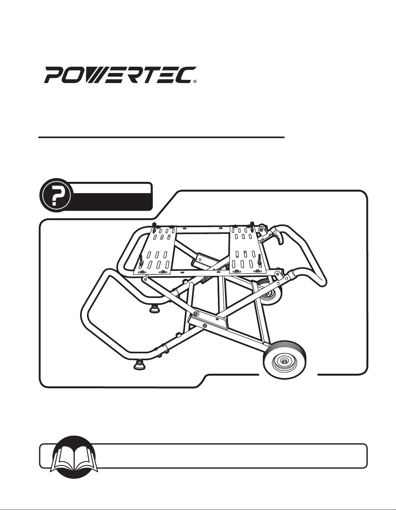
Owner’s Manual
TABLE SAW STAND
QUESTION...
1•847•780•6120
Model No. MT4009
Visit us on the web at www.powertecproducts.com
You will need this manual for safety instructions, operating procedures, and warranty.
Put it and the original sales invoice in a safe, dry place for future reference.
18_0621
Page 2
TABLE OF CONTENTS
PRODUCT
SECTION PAGE
SAFETY RULES 1
ASSEMBLY 2
Unpacking
Tools Needed
Assembly
Unfold the Main Frame
Attach the Footrest and Feet
Attach the Wheels
Attach the Handle
Attach the Lever Assembly
Mounting the Saw
OPERATION 5
Folding and Unfolding the Stand
Transportation and Storage
SPECIFICATIONS
Net Weight: ......................................35.3 lbs (16 kg)
Maximum Weight Capacity: ............. 331 lbs (150 kg)
Maximum Mounting Space: ............. 21-3/4" x 18-1/4"
(55.25 mm x 46.4 mm)
Stand Height: ...................................22-5/8" (57.5 mm)
MAINTENANCE 6
General Maintenance
PARTS ILLUSTRATION 7
AND LIST
WARRANTY 8
Page 3
SAFETY RULES
WARNING
For your own safety, read all of the rules and precautions
before operating tool.
WARNING
Always follow proper operating procedures as defined in
this manual even if you are familiar with use of this table
saw stand or any tool used with this stand. Remember
that being careless for even a fraction of a second can
result in severe personal injury.
You must be familiar with the use of any tool or accessory
used with this table saw stand. The supplier cannot
be held responsible for any accident, injury or damage
incurred while using this stand with any tool.
WARNING
Some dust created by operation of power tool contain
chemicals known to the State of California to cause
cancer, birth defects or other reproductive harm. To
reduce your exposure to these chemicals, work in a well
ventilated area and work with approved safety equipment.
Always wear OSHA/NIOSH approved, properly fitting face
mask or respirator when using such tools.
CAUTION
Do not modify or use this stand for any application other
than that for which it was designed.
SAFETY FOR WORK STAND
• Do not attempt to assemble or operate your table saw
stand until you have read the safety instructions in
this section.
• Only use your table saw stand on a hard, dry and
flat surface.
• Keep your work area clean and well lit. Cluttered or dark
areas invite accidents.
• Do not overreach. Keep proper footing and balance at
all times.
• Do not load the table saw stand with more than 331 lbs
(150 kg).
1
• Store properly. Do not store the table saw stand
outdoors or in a damp location.
• Do not stand or climb on table saw stand. It could tip
over, causing serious injury.
• Do not permit children to use the table saw stand
unsupervised. It is not a toy.
• Test for stability of the table saw stand before using
your saw and table saw stand.
• Dress properly. Do not wear loose clothing or jewelry.
Keep your hair, clothing and gloves away from moving
parts. Loose clothes, jewelry or long hair can be caught
in moving parts. Always wear non-slip footwear. Tie
back long hair. Roll long sleeves above the elbow.
• Always firmly attach the saw used with this stand. Do
not attempt to use the saw on the table saw stand until
the saw is fastened firmly.
• Be sure all hardware mounting the saw to the table top
is tight before folding and transporting the saw on the
table saw stand.
• Take care when folding the table saw stand to reduce
the hazard of pinching hands and fingers.
• Be aware of tipping. When a large piece is cut from one
end of a job, the remaining piece may be heavy enough
to tip the table saw stand. Always ensure the workpiece
is well supported.
• Always keep all guards in place. Be sure all power tool
guards are in good working order and are in proper
adjustment and alignment.
• Always keep your hands away from the cutting area.
CAUTION
Think safety! Safety is a combination of operator common
sense and alertness at all times when tool is being used.
WARNING
Do not attempt to operate tool until it is completely
assembled according to the instructions.
SAVE ALL WARNINGS AND INSTRUCTIONS
FOR FUTURE REFERENCE
SAFETY RULES
1
Page 4
ASSEMBLY
2
ASSEMBLY
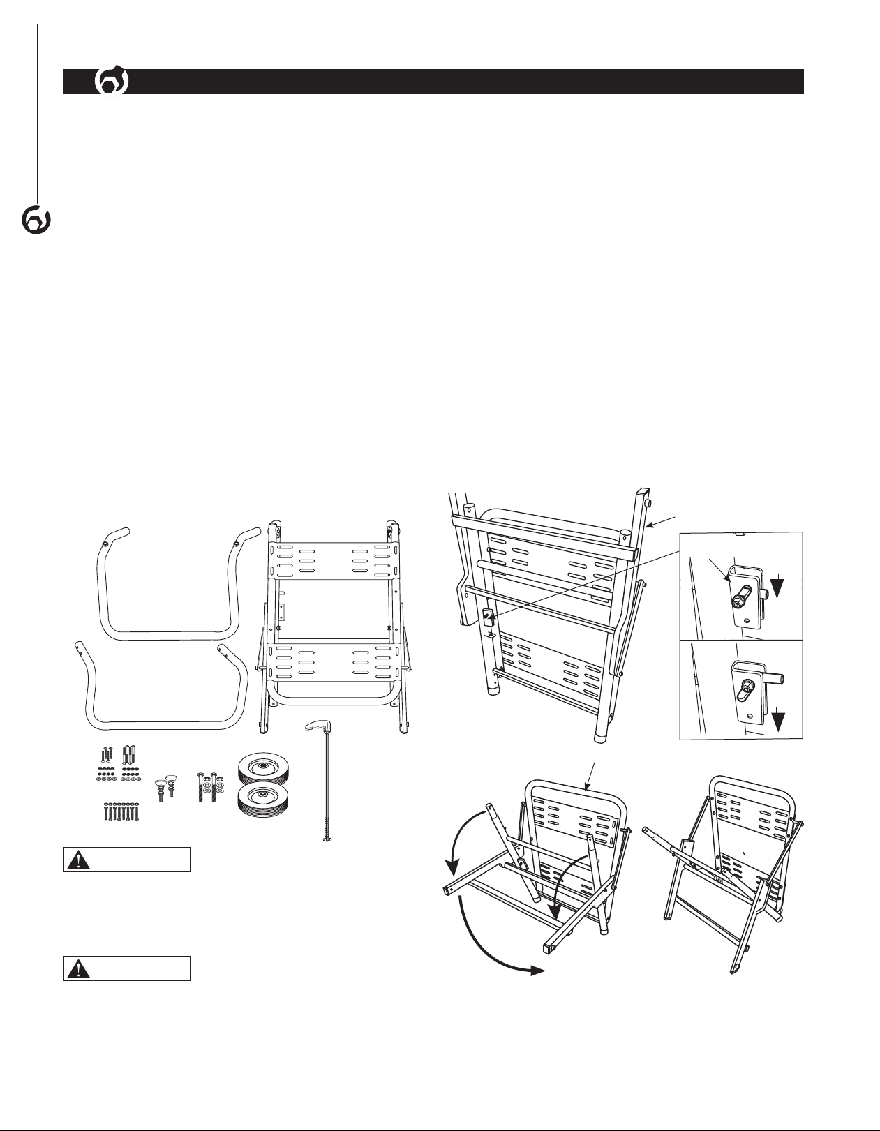
UNPACKING
Refer to Figure 1
Check for shipping damage. Check immediately that all
parts and accessories are included.
ITEM DESCRIPTION QTY
A Main Frame 1
B Footrest 1
2
C Feet 2
D Wheels 2
E Handle 2
F Lever Assembly 1
G Wheel Bolts M12x 80 (Wheel) 2
H Flat Washers (Wheel) 4
I Hex Locking Nut M12 (Wheel) 2
J Button Head Screws M8x40 (Footrest/
Handle)
K Hex Locking Nut M8 (Footrest/Handle) 8
L Saw Mounting Hardware - 1-3/4" set
(Mounting Bolt, Washer, Lock Washers
and Nut)
M Saw Mounting Hardware 2-1/2" set
(Mounting Bolt, Washer, Lock Washers
and Nut)
Figure 1
B
A
TOOLS NEEDED
The following tools (not included) are needed to assemble
the table saw stand:
1 - 13 mm wrench (Footrest, Handle Assembly and 1-3/4"
Mounting Hardware)
1 - 5 mm wrench (Footrest, Handle Assembly and 2-1/2"
Mounting Hardware)
1 - 8 mm wrench (Lever Assembly)
2 - 19 mm wrench (Footrest, Wheels Assembly)
1 - 8 mm wrench (Footrest, Wheels Assembly)
1 - Phillips screw driver (Lever Assembly)
ASSEMBLY
8
Unfold the Main Frame
Refer to Figure 2–3
4
• Push locking mechanism down and unfold the main
frame as shown in Figures 2–3.
4
Figure 2
Main Frame
Locking
Mechanism
E
C
F
K
J
L M
I
G
H
D
WARNING
Do not use the table saw stand until it is completely
assembled and you have read and understood this entire
operating manual and the operating manual of the tool
being used with this table saw stand.
WARNING
Do not use the table saw stand for scaffolding or as a
ladder. Make sure to securely tighten all fasteners before
using. Maximum capacity is 331 lbs (150 kg).
Figure 3
Main Frame
Page 5

ASSEMBLY
Attach the Footrest and Feet
Refer to Figure 4–5
• Slide the footrest onto the main frame and secure with
four button head screws and four hex locking nuts (two
on each side).
• Screw the feet into the footrest as shown in Figure 5.
The adjustable nut on the feet can be used to level and
adjust the height of the stand.
Figure 4
Footrest
Main Frame
• Repeat with other wheel.
Figure 6
Main Frame
Raised Hub
Flat
Washer
Wheel Bolt
3
ASSEMBLY
3
Figure 5
Foot
Adjustment
Nut
Footrest
Button Head
Hex
Locking
Nuts
Screws
Hex
Locking
Nut
Flat
Washer
Wheel
Attach the Handle
Refer to Figure 7
• Slide the handle onto the main frame and secure with
four button head screws and four hex locking nuts (two
on each side).
Figure 7
Handle
Main Frame
Hex Locking Nuts
Button Head
Screws
Attach the Wheels
Refer to Figure 6
• Orient the wheel with the raised hub next to the main
frame. Place a flat washer onto the wheel bolt, slide the
wheel bolt through the wheel and another flat washer (a
washer should be on each side of the wheel) and then
thread the wheel bolt through the threaded boss on the
main frame. Make sure the wheel turns freely and then
secure with hex locking nut. DO NOT over tighten, if too
tight the wheel will not turn.
Page 6

Attach the Lever Assembly
ASSEMBLY
Refer to Figure 8–10
• Remove the bolt, washers, nut, large washer and spring
from the lever assembly (See Figure 10).
• Place the large washer and spring between the locking
mechanism and the welded bracket as shown in
Figure 8.
• Slide the lever through the holes in the frame, spring,
4
large washer and into the locking mechanism.
• Align the holes in the locking mechanism and the lever
assembly rod. Secure in place with bolt, washers and
nut as shown in Figure 10. Tighten nut.
Figure 8
Locking Mechanism
Lever
Assembly
Rod
Large Washer
Spring
Welded Bracket
Figure 9
Release Lever Rod
Holes
in
Frame
Mounting the Saw
Refer to Figure 11
WARNING
Risk of accidental starting and serious personal injury.
Unplug the saw before attaching it to the saw stand.
WARNING
Risk of serious personal injury. Always make sure the saw
is fully supported and securely attached to a level work
surface. Make sure the table saw stand is located on a
flat surface.
NOTE: There are two sets of mounting hardware, a
1-3/4" set for mounting to the table top and a 2-1/2" set
for mounting a larger saw directly to the frame using the
holes in the frame.
• Place the saw to be used on the table top.
• Move the saw around until the hole pattern matches
the slot combination on the table top, secure with the
mounting hardware (1-3/4" set) supplied.
• Insert the bolt through the bottom of the table and
secure with flat washer, lock washer and nut.
NOTE: When mounting a larger saw directly to the
frame using the mounting hardware (2-1/2" set) supplied
ALWAYS insert the bolt through the bottom of the table
and secure with flat washer, lock washer and nut.
Figure 11
Nut
Lock
Washer
Flat
Washer
Locking
Mechanism
Figure 10
Locking Mechanism
Washer
Nut
Bolt
Washer
Large Washer
Lever
Assembly
Rod
Bolt
Holes in
Frame
Page 7

OPERATION
WARNING
Do not use the table saw stand for scaffolding or as a
ladder. Make sure to securely tighten all fasteners before
using. Maximum capacity is 331 lbs (150 kg).
Folding and Unfolding the Stand
Refer to Figure 12
NOTE: Take care when folding and unfolding the stand to
reduce the hazard of pinching hands and fingers.
To Fold
• While holding the handle, pull the lever and lift up on
the handle, the table top will tilt down and the frame will
fold close.
To Unfold
• While holding the handle, pull the lever and push down
on the handle until it clicks into place.
Figure 12
Figure 13
Figure 14
5
OPERATION
5
Transportation and Storage
Refer to Figure 13, 14
WARNING
Risk of unsafe operation. Ensure proper footing and use
caution when rolling the table saw stand to prevent tipping
or loss of balance.
• See the Folding and Unfolding the Stand paragraph
to place the stand in the folded position.
• To move the stand, use handle to lift and tilt the table
saw stand onto the wheels. Move table saw stand
as shown.
• Holding the handle, carefully lower the stand to
the ground.
• The stand may be stored in the vertical or
horizontal position with the tool attached.
Page 8

6
MAINTENANCE
MAINTENANCE
GENERAL MAINTENANCE
WARNING
When servicing, use only identical replacement parts. Use
of any other parts may create a hazard or cause product
damage. To ensure safety and reliability, all repairs
should be performed by a qualified service technician.
6
WARNING
Keep the table saw stand dry, clean, and free from oil and
grease. Always use a clean cloth when cleaning. Never
use brake fluids, gasoline, petroleum based products
or any strong solvent to clean the table saw stand .
Chemicals can damage, weaken or destroy plastic which
may result in serious personal injury.
Page 9

TABLE SAW STAND PARTS ILLUSTRATION AND LIST
7
PARTS LIST
7
Key# Part# Description Specifications Qty
1 MT4009001 Nut M8 6
2 MT4009002 Locking Handle ABS 1
3 MT4009003 Flat Washer 24
4 MT4009004 Locking Shaft Ø8 1
5 MT4009005 Handle 25x1.2 1
6 MT4009006 Hexagon Socket Button
Head Screws
7 MT4009007 Hex Locking Nut M8 22
8 MT4009008 Tube Sleeve 2
9 MT4009009 Wheels 2
10 MT4009010 End Cap 40x20 4
11 MT4009011 Wheel Housing Welded
Part
12 MT4009012 Wheel Bolt M12x80 2
13 MT4009013 Flat Washer 4
14 MT4009014 Hex Nut M12 2
15 MT4009015 End Cap 30x15 2
16 MT4009016 Hexagon Socket Button
Head Screws
17 MT4009017 Axle Housing Ø15 2
18 MT4009018 Hexagon Socket Button
Head Screws
19 MT4009019 Lock Washer 6
20 MT4009020 Support Frame 1
M8x40 8
1
M8x75 2
M8*16 2
Key# Part# Description Specifications Qty
21 MT4009021 Rubber Mat φ17*14 4
22 MT4009022 Cross Recessed
Countersunk Head Tapping
Screws
23 MT4009023 Levelling Pads M12x55,φ40 2
24 MT4009024 Foot Frame 1
25 MT4009025 Spring φ10*38 1
26 MT4009026 Locking Pin 1
27 MT4009027 Phillip Pan Head Screw M4x20 2
28 MT4009028 Flat Washer 4
29 MT4009029 Nut M4 2
30 MT4009030 Lock 1
31 MT4009031 Spring φ11x52 1
32 MT4009032 Frame Fixing Plate 2
33 MT4009033 Hexagon Socket Button
Head Screws
34 MT4009034 Worktop 1
35 MT4009035 Hexagon Socket Button
Head Screws
36 MT4009036 Mounting Bracket Worktop 2
37 MT4009037 Endcaps φ32 2
38 MT4009038 Carriage Bolt M8x45 M8x45 4
MT4009039 Button Head Screws
M8X55
M4.2x16 4
M8x85 2
M8x45 10
M8x65 4
Page 10

WARRANTY
8
Thank you for investing in a POWERTEC power tool. This product has been designed and manufactured to meet high
quality standards and is guaranteed for domestic use against defects in workmanship or material for a period of 12
months from the date of purchase. This guarantee does not affect your statutory rights.
SOUTHERN TECHNOLOGIES LLC. BENCH TOP AND STATIONARY POWER TOOL
LIMITED 1 YEAR WARRANTY AND 30-DAY SATISFACTION GUARANTEE POLICY
POWERTEC products are designed and manufactured by Southern Technologies LLC. All warranty communications
should be directed to Southern Technologies LLC by calling 847-780-6120, 9 AM to 5 PM, Monday through Friday,
8
US Central Time.
30- DAY SATISFACTION GUARANTEE POLICY
During the first 30 days after the date of purchase, if you are dissatisfied with the performance of this POWERTEC tool
for any reason, you may return the tool to the retailer from which it was purchased for a full refund or exchange. You
must present proof of purchase and return all original equipment packaged with the original product. The replacement
tool will be covered by the limited warranty for the balance of the one year warranty period.
LIMITED ONE YEAR WARRANTY
This warranty covers all defects in workmanship or materials in this POWERTEC tool for a one year period from the
date of purchase. This warranty is specific to this tool. Southern Technologies, LLC reserves the right to repair or
replace the defective tool, at its discretion.
WARRANTY
HOW TO OBTAIN SERVICE
To obtain service for this POWERTEC tool you must return it, freight prepaid, to POWERTEC. You may call (toll
free) 847-780-6120 for more information. When requesting warranty service, you must present the proof of purchase
documentation, which includes a date of purchase. POWERTEC will either repair or replace any defective part, at
our option at no cost to you. The repaired or replacement unit will be covered by the same limited warranty for the
remainder of the one year warranty period.
WHAT IS NOT COVERED
This warranty applies to the original purchaser at retail and may not be transferred.
This warranty does not cover consumable items such as saw blades, knives, belts, discs, cooling blocks and sleeves.
This warranty does not cover required service and part replacement resulting from normal wear and tear, including
accessory wear.
This warranty does not cover any malfunction, failure or defect resulting from:
1) misuse, abuse, neglect and mishandling not in accordance with the owner’s manual.
2) damage due to accidents, natural disasters, power outage, or power overload.
3) commercial or rental use.
4) alteration, modification or repair performed by persons not recommended by POWERTEC.
DISCLAIMER
To the extent permitted by applicable law, all implied warranties, including warranties of MERCHANTABILITY or
FITNESS FOR A PARTICULAR PURPOSE, are disclaimed. Any implied warranties, that cannot be disclaimed under
state law are limited to one year from the date of purchase. Southern Technologies LLC. is not responsible for direct,
indirect, incidental or consequential damages. Some states do not allow limitations on how long an implied warranty
lasts and/or do not allow the exclusion or limitation of incidental or consequential damages, so the above limitations may
not apply to you. This warranty gives you specific legal rights, and you may also have other rights which vary from state
to state. Southern Technologies LLC., makes no warranties, representations, or promises as to the quality or
performance of its power tools other than those specifically stated in this warranty.
Page 11

Page 12

Southern Technologies, LLC,
Waukegan, IL 60087
 Loading...