

Page 1
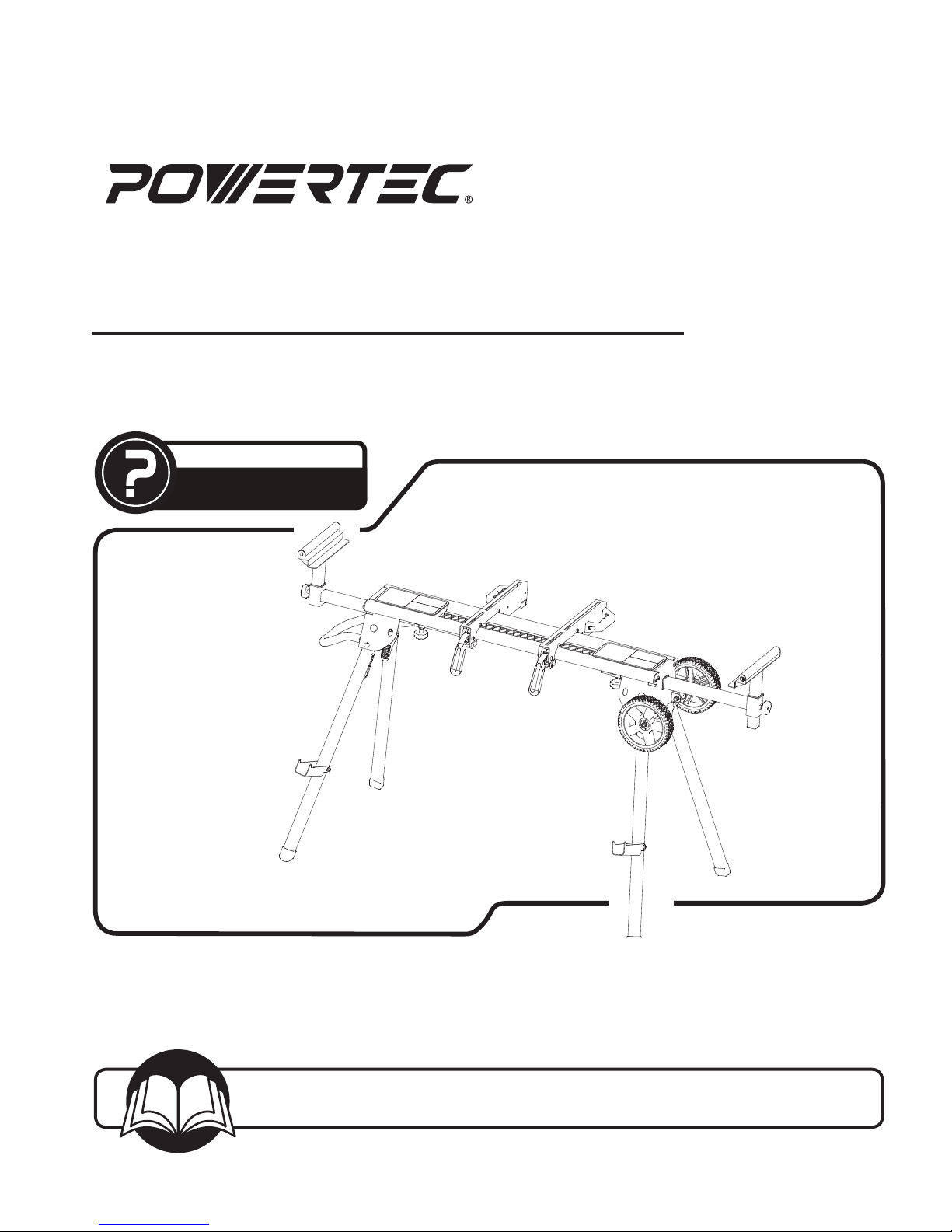
Owner’s Manual
Model No. MT4008
MITER SAW STAND
You will need this manual for safety instructions, operating procedures, and warranty.
Put it and the original sales invoice in a safe, dry place for future reference.
Visit us on the web at www.southerntechllc.com
17-1109
QUESTION...
1•847•780•6120
Page 2
PRODUCT
SPECIFICATIONS
Height .......................... 33-1/4" (846 mm)
Extended Width ...........42–65-1/4 (1067–1657 mm)
Maximum Load Capacity ..............330 lbs (150 kg)
Net Weight .......................29.3 lbs. (13.3 kg)
Gross Weight .....................33.7 lbs. (15.3 kg)
TABLE OF CONTENTS
SAFETY RULES 1
ASSEMBLY 2
Unpacking
Tools Needed
Assemble Handle
Unfold the Work Legs
Assemble Wheels
Assemble Roller Bar/ Extension Bar
Locking Knobs
Mounting the Miter Saw
OPERATIONS 4
Roller Bars/Extension Bars Adjustment
Material Supports
Transportation
MAINTENANCE 5
General Maintenance
Adjust Quick Release Bracket
PARTS ILLUSTRATION 6
& LIST
WARRANTY 8
SECTION PAGE
Page 3
SAFETY RULES
1
1
SAFETY RULES
WARNING
For your own safety, read all of the rules and precautions
before operating tool.
WARNING
Always follow proper operating procedures as defined in
this manual even if you are familiar with use of this miter
saw stand or any tool used with this stand. Remember
that being careless for even a fraction of a second can
result in severe personal injury.
You must be familiar with the use of any tool or accessory
used with this miter saw stand. The supplier cannot
be held responsible for any accident, injury or damage
incurred while using this stand with any tool.
WARNING
Some dust created by operation of power tool contains
chemicals known to the State of California to cause
cancer, birth defects or other reproductive harm. To
reduce your exposure to these chemicals, work in a well
ventilated area and work with approved safety equipment.
Always wear OSHA/NIOSH approved, properly fitting face
mask or respirator when using such tools.
CAUTION
Do not modify or use this stand for any application other
than that for which it was designed.
ELECTRICAL SAFETY
• Power tool plugs must match the outlet. Never modify
the plug in any way. Do not use any adapter plugs with
grounded power tools. Unmodified plugs and matching
outlets will reduce the risk of electric shock.
• Avoid body contact with grounded surfaces, such as
pipes, radiators, ranges, and refrigerators. There is an
increased risk of electric shock if your body is grounded.
• Do not expose power tools to rain or wet conditions.
Water entering a power tool will increase the risk of
electric shock.
• Do not abuse the cord. Never use the cord for carrying,
pulling, or unplugging the power tool. Keep the cord
away from heat, oil, sharp edges, or moving parts.
Damaged or entangled cords increase the risk of
electric shock.
• When operating a power tool outdoors, use an
extension cord suitable for outdoor use. Use of a cord
suitable for outdoor use reduces the risk of electric
shock. If operating a power tool in a damp location is
unavoidable, use a ground fault circuit interrupter (GFCl}
protected supply. Use of a GFCI reduces the risk of
electric shock.
SAFETY FOR WORK STAND
• Do not attempt to assemble or operate your miter saw
stand until you have read the safety instructions in this
section.
• Only use your miter saw stand on a hard, dry and flat
surface.
• Keep your work area clean and well lit. Cluttered or dark
areas invite accidents.
• Do not overreach. Keep proper footing and balance at
all times.
• Do not load the miter saw stand with more than 330 Ibs
(150 kg).
• Store properly. Do not store the miter saw stand
outdoors or in a damp location.
• Do not stand or climb on miter saw stand. It could tip
over, causing serious injury.
• Do not permit children to use the miter saw stand
unsupervised. It is not a toy.
• Be sure all locking pins are in the set-up position holes
before using your miter saw and miter saw miter saw
stand.
• Take care when moving the stand, especially when a
miter saw is mounted.
• Dress properly. Do not wear loose clothing or jewelry.
Keep your hair, clothing and gloves away from moving
parts. Loose clothes, jewelry or long hair can be caught
in moving parts. Always wear non-slip footwear. Tie
back long hair. Roll long sleeves above the elbow.
• Always firmly attach the miter saw used with this stand.
Do not attempt to use the miter saw on the miter saw
stand until the miter saw is fastened firmly.
• Be aware of tipping. When a large piece is cut from one
end of a job, the remaining piece may be heavy enough
to tip the miter saw stand. Always ensure the workpiece
is well supported.
• Always keep all guards in place. Be sure all power tool
guards are in good working order and are in proper
adjustment and alignment.
• Always keep your hands away from the cutting area.
CAUTION
Think safety! Safety is a combination of operator common
sense and alertness at all times when tool is being used.
WARNING
Do not attempt to operate tool until it is completely
assembled according to the instructions.
SAVE ALL WARNINGS AND INSTRUCTIONS
FOR FUTURE REFERENCE
Page 4
2
ASSEMBLY
ASSEMBLY
2
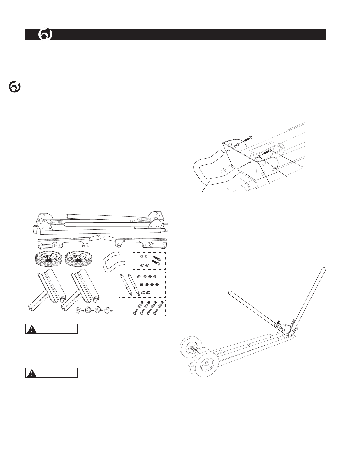
UNPACKING
Refer to Figure 1
Check for shipping damage. Check immediately whether
all parts and accessories are included.
ITEM DESCRIPTION QTY
A Miter Saw Stand 1
B Quick Release Mounting Brackets 2
C Roller Bars 2
D Locking Knobs, plain threads (roller bars) 2
E Locking Knobs, threads with plastic cap
(extension bar)
2
F Wheels 2
G Axle 2
H Locking Nut M8 (wheels) 4
I Washer Ø8 [wheels (4), handle (2)] 6
J Washer Ø12 (wheels) 2
K Handle 1
L Bolt (handle) 2
M Lock Washer (handle) 2
N Miter Saw Mounting Hardware
(mounting bolt, washer, lock washers
and nut)
4
A
B
M
F
C
H
D
E
G
N
I
K
L
J
Figure 1
I
WARNING
Do not use the miter saw stand until it is completely
assembled and you have read and understood this entire
operating manual and the operating manual of the tool
being used with this miter saw stand.
WARNING
Do not use the miter saw stand for scaffolding or as a
ladder. Make sure to securely tighten all fasteners before
using. Maximum capacity is 330 lbs (150 kg). Power tools
on the miter saw stand should not exceed a combined
overall height of 60" (152.4 cm) from the floor.
TOOLS NEEDED
The following tools (not included) are needed to assemble
the miter saw stand:
Phillips screwdriver
13 mm wrench or socket
ASSEMBLE HANDLE
Refer to Figure 2
• Secure handle to frame with hardware supplied.
Figure 2
Bolt
Handle
Lock
Washer
Washer (Ø8)
UNFOLD THE WORK LEGS
Refer to Figure 3
• Place the miter saw stand on a flat surface with the
folded legs facing up.
• Depress the release lever and rotate the leg until it
clicks and locks into the open position. Repeat for
each leg.
Figure 3
• Place the miter saw stand in the upright position on a
flat surface.
Page 5

3
ASSEMBLY
ASSEMBLY
3
ASSEMBLE WHEELS
Refer to Figure 4
• Slide the axle through the axle bracket, turn the axle
until the machined end fits into the inside bracket
hole. Place one small (Ø8) washer and nut onto axle.
Tighten nut.
NOTE: The axle has a retaining ring on one end and is
machined to fit the axle bracket hole on the other end,
make sure the machined end is inserted into the axle
bracket first.
• Slide one larger (Ø12) washer and the wheel on the
axle. Secure in place with the small (Ø8) washer and
nut. Tighten nut. NOTE: Raised hub goes to the inside.
• Repeat with other wheel.
Figure 4
Axle
Wheel
Nut
Washer
(Ø8)
Washer
(Ø8)
Nut
Washer
(Ø12)
Axle Bracket
Retaining
Ring
ASSEMBLE ROLLER BAR/ EXTENSION BAR
LOCKING KNOBS
Refer to Figure 5
• Place the roller arms into the roller bar supports, slide
up and down to desired location and secure in place
with locking knobs (plain threads).
• Assemble locking knobs (threads with plastic cap) to the
bottom of the frame as shown.
Figure 5
Roller Bar
Locking Knob
Locking
Knob
MOUNTING THE MITER SAW
Refer to Figure 6-7
WARNING
Risk of accidental starting and serious personal injury.
Unplug the miter saw before attaching it to the miter saw
stand.
WARNING
Risk of serious personal injury. Always make sure the
miter saw is fully supported and securely attached to
a level work surface. Make sure the miter saw stand is
located on a flat surface.
WARNING
Do not mount a table saw on this miter saw stand.
Aggressive feeding of sheet materials into a table saw
could cause the stand to tip over.
NOTE: This miter saws stand is to be used with miter
saws with four mounting holes in a rectangular pattern
• Mount the miter saw to the quick-release mounting
brackets using the supplied hardware (mounting bolt,
washer, lock washers and nut) as shown.
Figure 6
Bolt
Lock Washer
Nut
Flat Washer
Page 6

• The quick release mounting brackets hook onto the
miter saw stand frame. Using the handles on the
quick release mounting brackets, lift the miter saw and
position the quick release mounting brackets onto the
miter saw stand as shown in Figure 7 (SAW IS NOT
SHOWN TO ALLOW VISIBILITY OF THE RAILS AND
BRACKETS).
Figure 7
• Lower the saw into place and press the locking levers
down to lock the mounting brackets into place.
OPERATION
4
WARNING
Do not use the miter saw stand for scaffolding or as a
ladder. Make sure to securely tighten all fasteners before
using. Maximum capacity is 330 lbs (150 kg). Power tools
on the miter saw stand should not exceed a combined
overall height of 60" (152.4 cm) from the floor.
NOTE: For your convenience this stand is equipped with
tool trays and a mesh bottom to help prevent accidental
dropping of tools.
ROLLERS BARS/EXTENSION BAR
ADJUSTMENT
Refer to Figure 8
The extension bars move in and out to properly support
the workpiece.
The roller bars are used as directional rollers or with the
extension bars as stationary stop guides.
• Loosen the locking knobs, slide the extension bar in or
out to the required position, tighten the locking knobs.
• Loosen the locking knobs, slide the roller bars up and
down to desired location, tighten the locking knobs.
MATERIAL SUPPORTS
Refer to Figure 8
Fold the material supports out to stack extra material for
easy excess.
Roller Bar
Locking
Knob
Material
Support
Extension
Bar
Locking
Knob
Tool Trays
Locking
Knob
Roller Bar
Material
Support
Locking
Knob
Figure 8
Tool Trays
Release
Levers
4
ASSEMBLY
OPERATION
4
Page 7

OPERATION
5
GENERAL MAINTENANCE
WARNING
When servicing, use only identical replacement parts. Use
of any other parts may create a hazard or cause product
damage. To ensure safety and reliability, all repairs
should be performed by a qualified service technician.
WARNING
Keep the miter saw stand dry, clean, and free from oil and
grease. Always use a clean cloth when cleaning. Never
use brake fluids, gasoline, petroleum based products
or any strong solvent to clean the miter saw stand .
Chemicals can damage, weaken or destroy plastic which
may result in serious personal injury
MAINTENANCE
5
MAINTENANCE
5
ADJUST QUICK RELEASE BRACKET
Refer to Figure 10
The quick release mounting brackets must be secure on
the miter saw stand. If adjustment is needed:
Turn the adjusting nut on the adjustment screw clockwise
to tighten the clamping tension.
Turn the adjusting nut on the adjustment screw
counterclockwise to loosen the clamping tension.
Adjustable
Nut
Figure 10
TRANSPORTATION
Refer to Figure 8, 9
WARNING
Risk of unsafe operation. Ensure proper footing and use
caution when rolling the miter saw stand to prevent tipping
or loss of balance.
• Lift up on the end of the miter saw stand with wheels.
• While holding the stand with one hand, squeeze the
release levers and fold up the two suspended legs. The
legs will lock into place.
• Lower the stand until the wheels rest on a flat surface.
• Using the handle, tilt the other end of the miter saw
stand up and transfer the weight to the wheels.
• Squeeze the release levers and fold up the remaining
two legs. The legs will lock into place.
• Holding the handle, carefully lower the stand to the
ground.
• To move the stand, use handle to lift and tilt the miter
saw stand onto the wheels. Move miter saw stand as
shown.
Figure 9
Page 8

MITER SAW STAND PARTS ILLUSTRATION
6
PARTS LIST
6
Page 9

MITER SAW STAND PARTS LIST
7
PARTS LIST
7
Key# Part# Description Specifications Qty
1 MT4008001 Body Tube 2
2 MT4008002 Storage Box PP 2
3 MT4008003 Legs Fixing Housing 1
4 MT4008004 Nylon Fixing Nut M8 4
5 MT4008005 Flat Washer Φ8 10
6 MT4008006 Flat Washer Φ12 2
7 MT4008007 C Clip Φ12 2
8 MT4008008 Axle 2
9 MT4008009 Pan Head Screws M6*12 8
10 MT4008010 Square Tube End Caps PP 4
11 MT4008011 Wheels 2
12 MT4008012 Bolt M6*14 8
13 MT4008013 Legs Fixing Housing 1
14 MT4008014 PH Screw M8*16 2
15 MT4008015 Split Washer 8 2
16 MT4008016 Handle 1
17 MT4008017 Rivet 5*10 16
18 MT4008018 Locking Knob M8*15 2
19 MT4008019 Extension Tube Fixing Part PP 2
20 MT4008020 Steel Net 1
21 MT4008021 Mounting Locking Handle 2
22 MT4008022 Cam Block ABS 2
23 MT4008023 FH Shoulder Screw 7*45 2
24 MT4008024 FH Shoulder Screw M6*45 4
25 MT4008025 Hex Bolt M6*20 4
26 MT4008026 Mounting Carrying Handle 2
27 MT4008027 Spring Pin Φ5*45 4
28 MT4008028 FH Shoulder Screw M6*35 2
Key# Part# Description Specifications Qty
29 MT4008029 M6 Nut M6 10
30 MT4008030 Saw Mounting Bracket 2
31 MT4008031 Mounting Bracket End Cap PE 4
32 MT4008032 Nylon Fixing Nut M6 8
33 MT4008033 Rear Clamp Jaw PP 2
34 MT4008034 Front Clamp Jaw PA6+GF20% 2
35 MT4008035 Split Washer 6 6
36 MT4008036 Flat Washer Φ6 8
37 MT4008037 Carriage Bolt M6*60 4
38 MT4008038 Roller 2
39 MT4008039 Work Support Welding Part 2
40 MT4008040 End Cap 4
41 MT4008041 Slotted Screw 10*34.5 4
42 MT4008042 End Cap 30*30 4
43 MT4008043 Work Support Welding Part PP M8*15 2
44 MT4008044 Extension Tube 2
45 MT4008045 PH Screw M6*8 2
46 MT4008046 Hexagon Socket Button Head
Screws
M6*46 2
47 MT4008047 Material Support 2
48 MT4008048 Legs 2
49 MT4008049 C Clip 6 4
50 MT4008050 Nylon Fixing Nut M10 4
51 MT4008051 Carriage Bolt M10*45 4
52 MT4008052 Locking Pin 4
53 MT4008053 Rivet 6*44 4
54 MT4008054 Quick Release Leg Lock Lever PP 4
55 MT4008055 Legs 2
56 MT4008056 Feet End Cap 4
Page 10

Thank you for investing in a POWERTEC power tool. This product has been designed and manufactured to meet high
quality standards and is guaranteed for domestic use against defects in workmanship or material for a period of 1 year
from the date of purchase. This guarantee does not affect your statutory rights.
SOUTHERN TECHNOLOGIES LLC. BENCH TOP AND STATIONARY POWER TOOL
LIMITED ONE YEAR WARRANTY AND 30-DAY SATISFACTION GUARANTEE POLICY
POWERTEC products are designed and manufactured by Southern Technologies LLC. All warranty communications
should be directed to Southern Technologies LLC by calling 847-780-6120, 9 AM to 5 PM, Monday through Friday,
US Central Time.
30- DAY SATISFACTION GUARANTEE POLICY
During the first 30 days after the date of purchase, if you are dissatisfied with the performance of this POWERTEC tool
for any reason, you may return the tool to the retailer from which it was purchased for a full refund or exchange. You
must present proof of purchase and return all original equipment packaged with the original product. The replacement
tool will be covered by the limited warranty for the balance of the one year warranty period.
LIMITED ONE YEAR WARRANTY
This warranty covers all defects in workmanship or materials in this POWERTEC tool for a one year period from the
date of purchase. This warranty is specific to this tool. Southern Technologies, LLC reserves the right to repair or
replace the defective tool, at its discretion.
HOW TO OBTAIN SERVICE
To obtain service for this POWERTEC tool you must return it, freight prepaid, to POWERTEC. You may call (toll free)
1-847-780-6120 for more information. When requesting warranty service, you must present the proof of purchase
documentation, which includes a date of purchase. POWERTEC will either repair or replace any defective part, at
our option at no cost to you. The repaired or replacement unit will be covered by the same limited warranty for the
remainder of the one year warranty period.
WHAT IS NOT COVERED
This warranty applies to the original purchaser at retail and may not be transferred.
This warranty does not cover consumable items such as saw blades, knives, belts, discs, cooling blocks and sleeves.
This warranty does not cover required service and part replacement resulting from normal wear and tear, including
accessory wear.
This warranty does not cover any malfunction, failure or defect resulting from:
1) misuse, abuse, neglect and mishandling not in accordance with the owner's manual.
2) damage due to accidents, natural disasters, power outage, or power overload.
3) commercial or rental use.
4) alteration, modification or repair performed by persons not recommended by POWERTEC.
DISCLAIMER
To the extent permitted by applicable law, all implied warranties, including warranties of MERCHANTABILITY or
FITNESS FOR A PARTICULAR PURPOSE, are disclaimed. Any implied warranties, that cannot be disclaimed under
state law are limited to one year from the date of purchase. Southern Technologies LLC. is not responsible for direct,
indirect, incidental or consequential damages. Some states do not allow limitations on how long an implied warranty
lasts and/or do not allow the exclusion or limitation of incidental or consequential damages, so the above limitations may
not apply to you. This warranty gives you specific legal rights, and you may also have other rights which vary from state
to state. Southern Technologies LLC., makes no warranties, representations, or promises as to the quality or
performance of its power tools other than those specifically stated in this warranty.
WARRANTY
8
WARRANTY
8
Page 11

NOTE
Page 12

Southern Technologies, LLC
3816 Hawthorn CT,
Waukegan, IL 60087
 Loading...