

Page 1
INSTRUCTION SHEET
MITER SAW STAND
QUESTION...
1•847•780•6120
IMPORTANT
Due to a manufacturing change the Owner's Manual
provided with your tool DOES NOT cover all of the
assembly. USE this sheet along with the provided Owner's
Manual to assemble this tool.
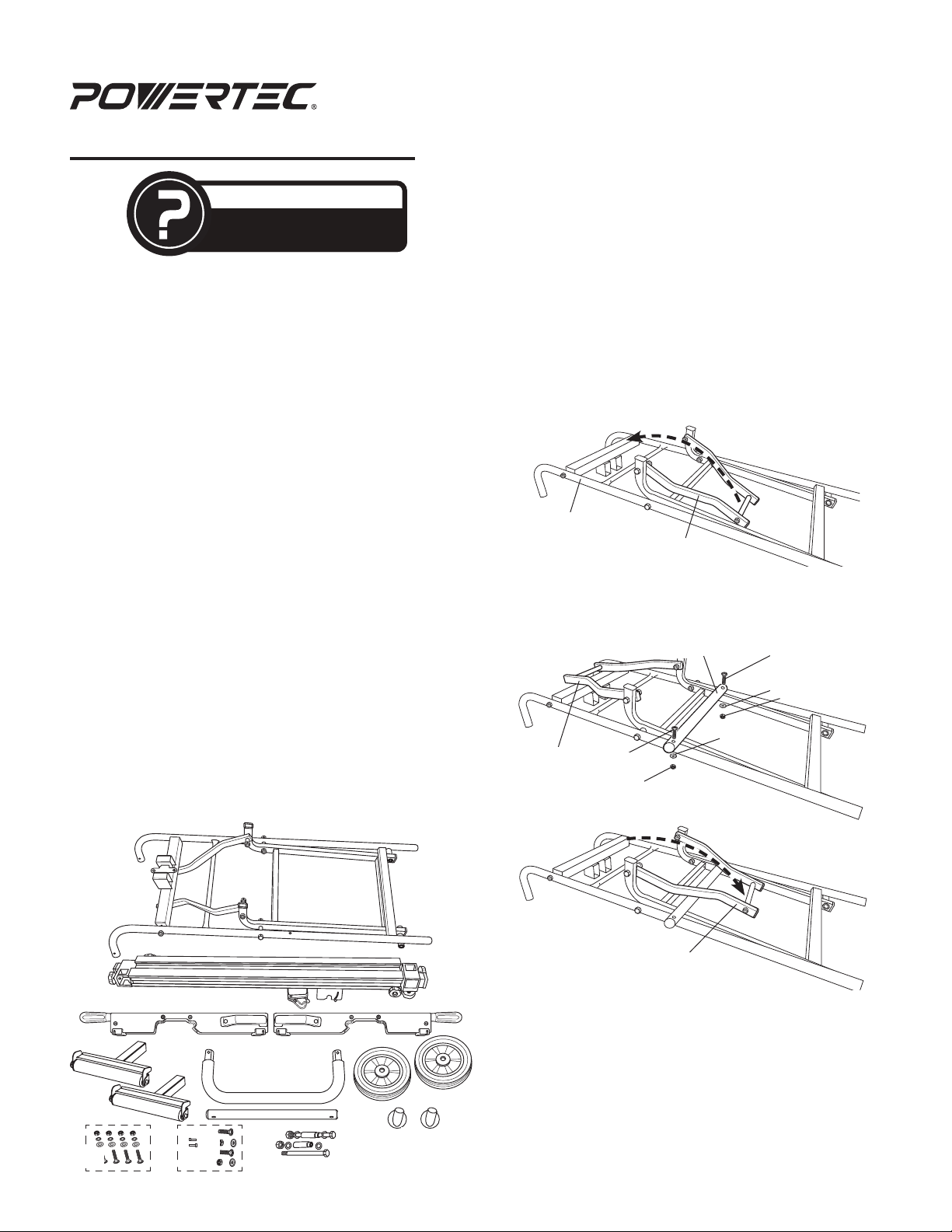
UNPACKING
Refer to Figure 1 on this sheet
Check for shipping damage. Check immediately that all
parts and accessories are included.
ITEM DESCRIPTION QTY
A Main Frame 1
B Top Frame 1
C Cross Bar 1
D Cross Bar Hardware (M6 bolt, washer, nut) 2
E Quick Release Mounting Brackets 2
F Roller Bars 2
G Handle 1
H Screw (handle) 2
I Wheels 2
J Bolts (wheel) 2
K Washers (wheel) 4
L Axle sleeves (wheel) 2
M Lock nuts (wheel) 2
N Feet 2
O Miter Saw Mounting Hardware
(mounting bolt, washer, lock washers and nut)
Figure 1
4
MT4002
TOOLS NEEDED
The following tools (not included) are needed to assemble
the miter saw stand:
1 - 4 mm hex wrench (Frame assembly)
1 - 10 mm open end wrench (Frame assembly)
1 - 13 mm socket (Frame assembly)
1 - Phillips screw driver (handle assembly)
2 - Adjustable wrenches or two 19 mm wrenches
(wheel assembly)
ASSEMBLE FRAME
Refer to Figure 2–6
• Place the main frame as shown in Figure 2. Rotate the
folding arm up.
Figure 2
Main Frame
folding arm
• Use the M6 bolts, washer and nuts to assemble the
cross bar to the main frame (Figure 3). Rotate the
folding arm back down after the crossbar is assembled.
Figure 3
Folding Arm
M6 Bolt
Nut
Cross Bar
Washer
M6 Bolt
Washer
Nut
A
folding arm down
B
E E
• Place the top frame upside down as shown in Figure 4.
Temporarily remove the bar lock and top frame
mounting nuts.
G
F
C
D
O
H
J
K L M
I
N
16-1108
Page 2
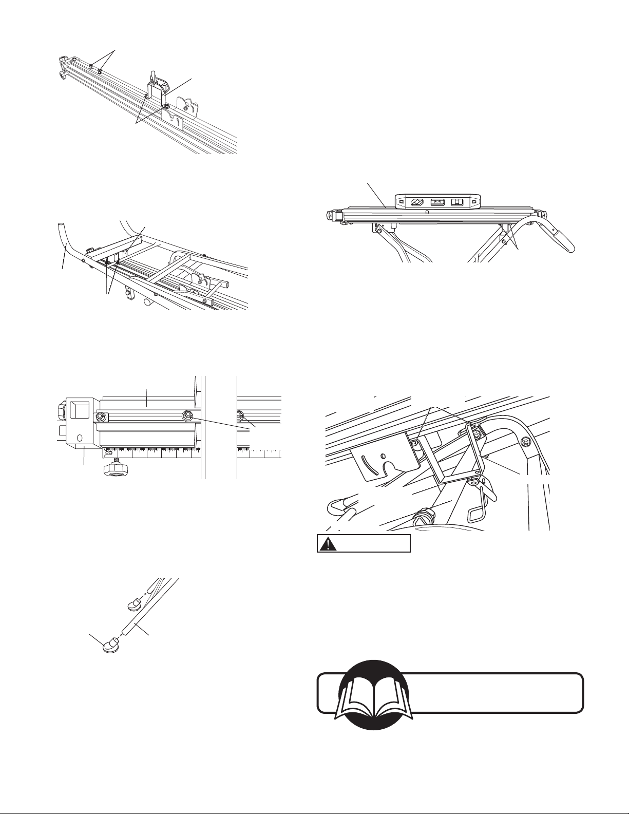
Figure 4
Top Frame Mounting Bolts and Nuts
Bar Lock
Mounting
Nuts
• With handles facing up, place the main frame onto the
top frame. Align the holes in the main frame mounting
bracket with the top frame mounting bolts (Figure 5).
NOTE: The crossbar clip will not be latched during
assembly of unit.
• Place a level on the on the top frame to ensure the miter
saw stand is level.
- If the top frame is level tighten the two top frame
mounting bolts.
- If the top frame is NOT level loosen the two top frame
mounting bolts and slide the top frame until it is level.
When level tighten the two top frame mounting bolts.
Figure 8
Top Frame
Figure 5
Handles
Facing Up
Top Frame
Mounting Bolts
Main Frame
Mounting Bracket
• Slide the main frame until it is approximately 6-1/2" from
the end of the left side of the top frame (Figure 6).
• Use a 13 mm socket to snug the two top frame mounting
bolts. DO NOT tighten at this time.
Figure 6
•
Top Frame
Main Frame
Top Frame
Mounting Bolts
21 3 4 5 6 7 8 9 10 11 12
• Assemble wheels and handle shown in the OWNERS
MANUAL
ASSEMBLE FEET
Refer to Figure 7
• Press the feet on to the end of each main frame leg.
Figure 7
Foot
Main Frame Leg
LEVEL TOP FRAME
Refer to Figure 8–9
• Roll the miter saw stand over to rest on the handle and
wheels as shown in Figure 4 of your Owner's Manual.
• Unfold the stand, refer to the Unfold the Miter Saw
Stand instructions in your Owner's Manual.
Top Frame
Mounting Bolts
• Reassemble the bar lock as shown. DO NOT tighten the
mounting bolts at this time.
• Slide latch pin up to release table support bar bracket
and lower top frame as shown in Figure 13 under To
Fold Stand For Storage in your Owner's Manual.
• Position the bar lock with the extended foot touching the
down side of the cross bar.
• Use a 13 mm socket to tighten the bar lock nuts.
Figure 9
Bar Lock
Extended Foot
Crossbar
Bar Lock Nuts
Bar Lock
WARNING
For your own safety, read all of the rules and precautions
before operating tool.
PLACE THIS SHEET WITH YOUR
MANUAL FOR FUTURE REFERENCE.
Visit us on the web at
www.southerntechllc.com
Put these instructions and the
original sales invoice in a safe,
dry place for future reference.
Southern Technologies, LLC
3816 Hawthorn CT,
Waukegan, IL 60087
 Loading...