

Page 1
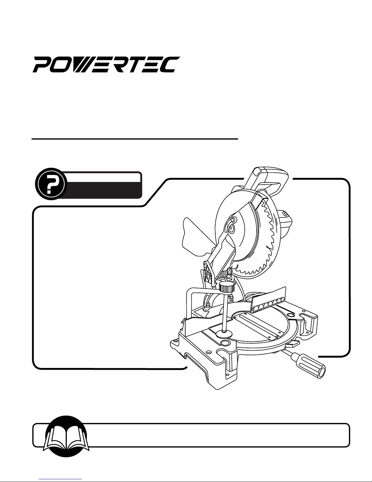
Model No. MSC1000
QUESTION...
1•877•393•7121
Owner’s Manual
10" COMPOUND MITER
SAW WITH LASER
Visit us on the web at www.southerntechllc.com
You will need this manual for safety instructions, operating procedures, and warranty.
Put it and the original sales invoice in a safe, dry place for future reference.
10-0106
Page 2
TABLE OF CONTENTS
SECTION PAGE
SAFETY RULES 1
Work Preparation
Work Area Preparation
Tool Maintenance
Tool Operation
ASSEMBLY 2
Mounting the miter saw
Installation of miter handle
Installation of rear extension stay
Installation of table extension
Cutting Head
Installation of dust bag
Installation of hold-down clamp assembly
Removal and installation of the blade
Fence Squareness Adjustment
Miter scale
Cutting arm travel adjustment
90° blade alignment
45° blade alignment
Laser alignment
Power source
Grounding instructions
Extension cords
Motor
Electrical Connections
TROUBLESHOOTING 13
PARTS ILLUSTRATION & 15
LIST
WARRANTY 16
PRODUCTION
SPECIFICATIONS
Horsepower (Maximum Developed)............................. 2 HP
Voltage..........................................................................120 V
Amperes..............................................................................15
Hertz...................................................................................60
Phase............................................................................Single
Motor RPM...........................................................4,800 RPM
Blade Diameter...............................................................10”
Depth of Cut at 90°............................................................. 3"
Depth of Cut at 45°.....................................................1-9/16"
OPERATION 9
Safety precautions
Body and hand position
Basic saw operation
Switch activation
Miter cut
Bevel cut
Compound cut
Cutting bowed material
Cutting base molding
Cutting crown molding
MAINTENANCE 12
Inspect and replace the motor brushes
Cleaning
Lubrication
Keep tool in repair
Page 3

SAFETY RULES
1
WARNING
For your own safety, read and understand all warnings
and operating instructions before using any tool or
equipment.
WARNING
Some dust created by operation of power tool contains
chemicals known to the State of California to cause
cancer, birth defects or other reproductive harm.
To reduce your exposure to these chemicals: work in a
well ventilated area and work with approved safety
equipment. Always wear OSHA/NIOSH approved,
properly fitting face mask or respirator when using such
tools.
WARNING
Failure to follow these rules may result in serious personal
injury. Remember that being careless for even a fraction
of a second can result in severe personal injury.
WORK PREPARATION
• Wear proper apparel. Do not wear loose clothing,
gloves, neckties, rings, bracelets or other jewelry which
may get caught in moving parts of the tool.
• Nonslip protective footwear is recommended. Wear
protective hair covering to contain long hair.
• Wear eye and hearing protection. Always use safety
glasses. Eye protection equipment should comply with
ANSI Z87.1 standards. Hearing equipment should
comply with ANSI S3.19 standards.
• Wear face mask or dust mask if operation is dusty.
• Be alert and think clearly. Never operate power tools
when tired, intoxicated or when taking medications that
cause drowsiness.
WORK AREA PREPARATION
• Keep work area clean. Cluttered work areas and
benches invite accidents.
• Work area should be properly lighted.
• Do not use the machine in a dangerous environment.
The use of power tools in damp or wet locations or in
rain can cause shock or electrocution.
• Three-prong plug should be plugged directly into
properly grounded, three-prong receptacle.
• Use the proper extension cord. Make sure your
extension cord is in good condition and should have a
grounding prong and the three wires of
extension cord should be of the correct gauge.
• Keep children and visitors away. Your shop is a poten tially dangerous environment. Children and visitors can
be injured.
• Make your workshop childproof with padlocks, master
switches or remove switch keys to prevent any uninten tional use of power tools.
TOOL MAINTENANCE
• Turn the machine "OFF", and disconnect the machine
from the power source prior to inspection.
• Maintain all tools and machines in peak condition. Keep
tools sharp and clean for best and safest performance.
• Follow instructions for lubricating and changing
accessories.
• Check for damaged parts. Check for alignment of
moving parts, binding, breakage, mounting and any
other condition that may affect tool's operation.
• Poorly maintained tools and machines can further
damage the tool or machine and/or cause injury.
• A guard or any other part that is damaged should be
repaired or replaced. Do not perform makeshift repairs.
TOOL OPERATION
• Avoid accidental start-up. Make sure that the tool is in
the “OFF” position before plugging in.
• Use the right tool for your job. Do not force your
tool or attachment to do a job for which it was not
designed.
• Disconnect tool when changing parts.
• Don't force the workpiece on the machine. Damage to
the machine and/or injury may result.
• Never leave tool running unattended. Turn the power off
and do not leave tool until it comes to a complete stop.
• Do not overreach. Loss of balance can make you fall
into a working machine, causing injury.
• Never stand on tool. Injury could occur if the tool tips, or
if you accidentally contact the cutting tool.
• Know your tool. Learn the tool’s operation, application
and specific limitations before using it.
• Use recommended accessories. Use of improper
accessories may cause damage to the machine or injury
to the user.
• Handle workpiece correctly. Keep hands away from
moving parts.
• Turn tool off if it jams. .
CAUTION: Think safety! Safety is a combination of operator common sense and alertness at all times when tool is
being used.
WARNING
Do not attempt to operate tool until it is completely
assembled according to the instructions.
Page 4
2
H
G
F E
D
C
B
A
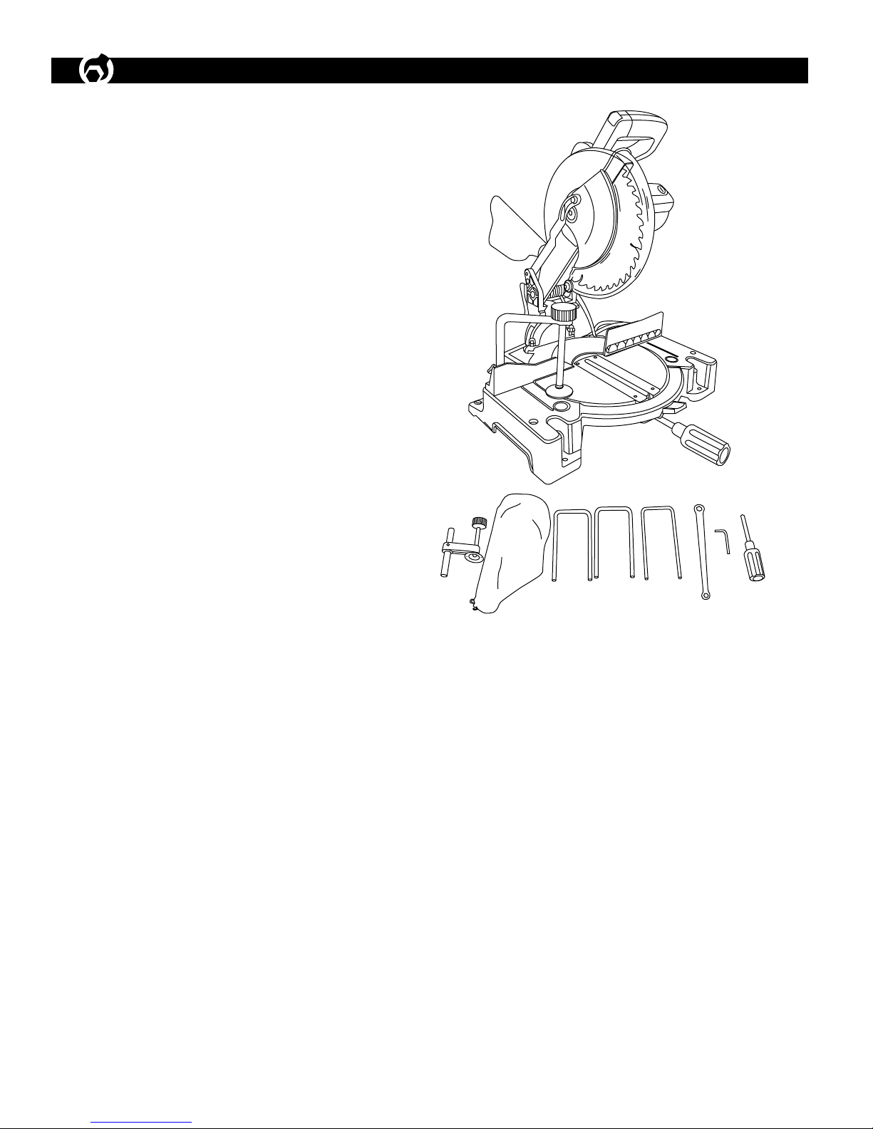
ASSEMBLY
UNPACKING
Check for shipping damage. If damage has occurred, a
claim must be filled with carrier. Check for completeness.
Immediately report missing parts to dealer.
You miter saw is shipped complete in one container.
Carefully unpack the table saw and all loose items from
the shipping container. Figure 1, illustrates the miter saw
and all loose parts.
A. Miter Saw
B. Miter Handle
C. Hex Wrench
D. Wrench
E. Rear Extension Stay
F. Table Extensions
G. Dust Bag
H. Hold-down Clamp Assembly
Page 5
CAUTION: Do not attempt assembly if parts are missing.
Ø3/8”
16-7/8”
7-1/2”
Miter handle
Rear extension stay
Table extension holes
Use this manual to order replacement parts.
INSTALLATION OF REAR EXTENSION STAY
ASSEMBLY
Refer to Figure 4
WARNING
Do not operate machine until completely assembled. Do
not operate machine until you have completely read and
understand this manual.
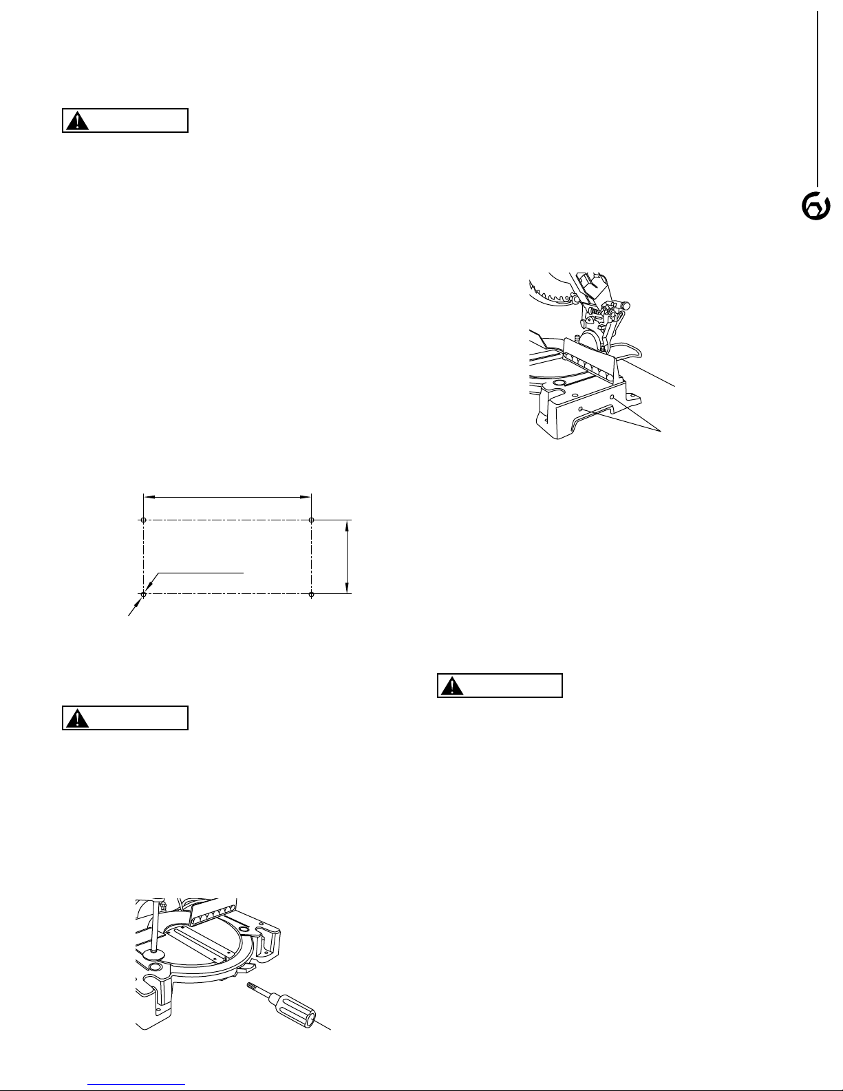
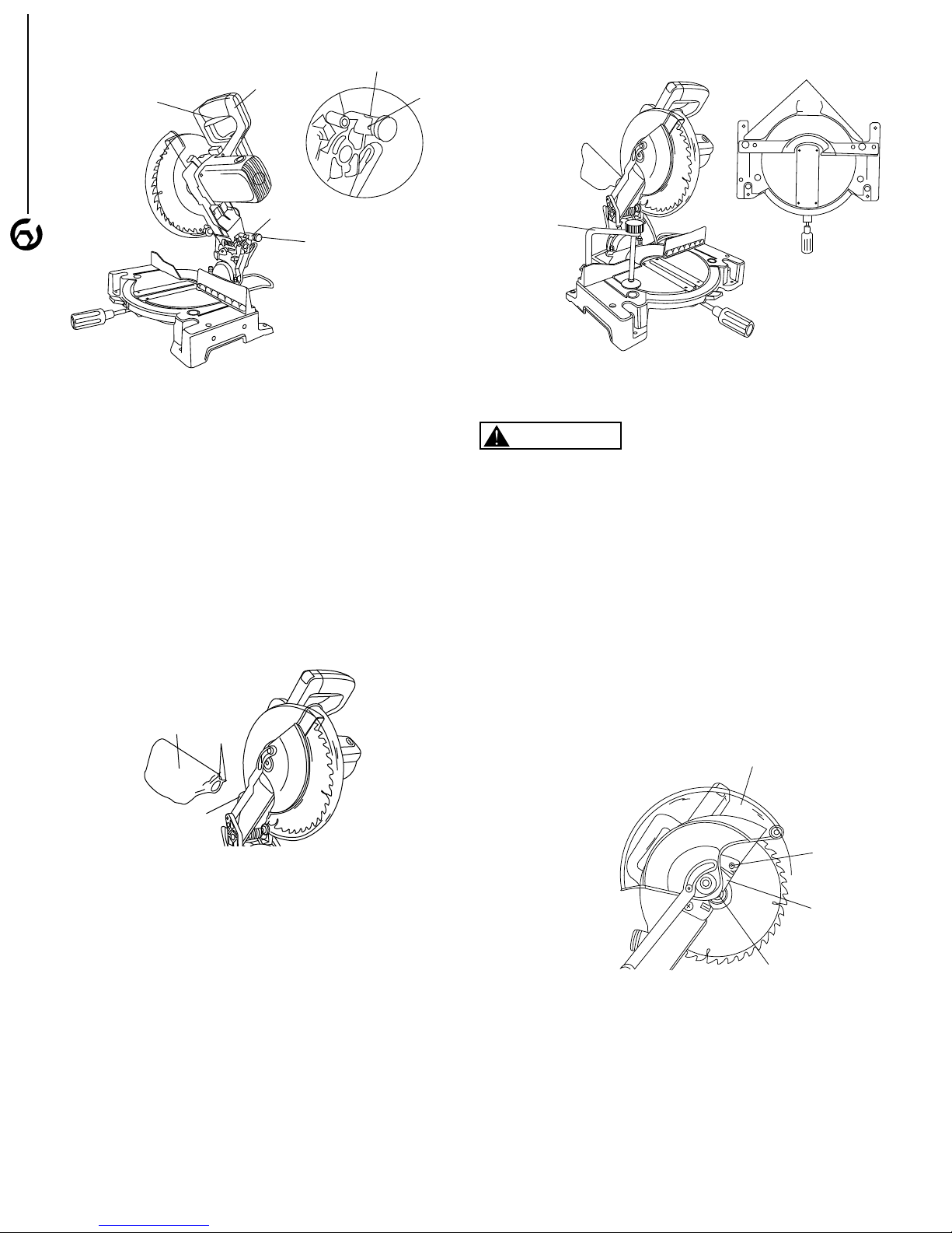
MOUNTING THE MITER SAW
Refer to Figure 2
• The miter saw must be installed in a well-lighted area
with correct power supply.
• The miter saw can be installed on either a workbench or
a tool stand by using bolts, lock washers, and hex nuts.
• The miter saw must be bolted to a firm and level
surface.
• There must be enough clearance for the moving
workpiece during operation and enough room for safety
operation of the machine.
• Figure 2 shows the base dimension and mounting
holds.
Figure 2
• Loosen the extension stay locking screw under the saw
base.
• Place the rear extension stay into the holes in the saw
base. Make sure the angle of the stay is in the down
position for maximum support.
• Insert the extension stay locking screw back to the hole
and tighten to hold the extension.
Figure 4
INSTALLATION OF TABLE EXTENSIONS
Refer to Figure 4
3
INSTALLATION OF MITER HANDLE
Refer to Figure 3
WARNING
Do not use the power cord or head assembly power
switch handle to carry the tool. Always lock the cutting
head in the down position when moving or storing the
saw.
• Insert the miter handle into the threaded hole located at
the front of the table.
Figure 3
• Loosen the extension locking screws located in the rear
of the saw base.
• Place the table extension into the holes in the saw base.
• Insert the extension locking screws back into the hole
and tighten to hold the extension.
CUTTING HEAD
WARNING
Always lock the cutting head in the down position while
transporting or storing the miter saw.
Always use the specified carrying handle. Never carry
the saw by the switch handle, the cutting arm or the miter
handle.
RAISING THE CUTTING HEAD
Refer to Figure 5
• Push down slightly on the saw handle.
• Pull the hold down latch out of the long slot of locking
hole and turn 90° to insert into the short slot.
• This now will allow the saw switch handle to be raised to
the up position.
Page 6
Dust Bag
Wire
Port
Hold down cl amp
Mounting hol es
Blade guard
Plate screw
Cover plate
Arbor bolt
Figure 5
Hold down lock
Slot
Switch handle
Short slot
Long slot
Trigger Switch
ASSEMBLY
4
LOCKING CUTTING HEAD IN DOWN
POSITION
• Push the switch handle down to the lowest position
• Pull the hold-down lock out of the short slot. Rotate 90°
to the lock position in the long slot.
Figure 7
REMOVAL AND INSTALLATION OF THE
BLADE
WARNING
Turn the switch to OFF position and disconnect the
machine from power source.
INSTALLATION OF DUST BAG
Refer to Figure 6
• Squeeze the wire located at the end of dust bag.
• Place the dust bag opening onto the dust port and
release the wire securing the dust bag onto the dust
port.
Figure 6
INSTALLATION OF THE HOLD-DOWN CLAMP
ASSEMBLY
Refer to Figure 7
• Loosen the lock knob from the rear side of the saw
base.
• Place the hold-down clamp assembly in one of the
mounting holes.
• Tighten the lock knob.
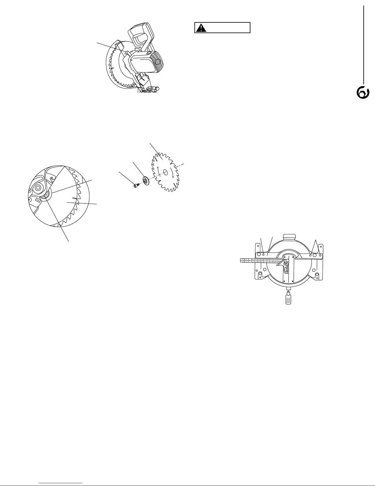
REMOVING BLADES
Refer to Figure 8, 9 and 10
• Raise the cutting head to the upright position.
• Raise the lower blade guard to the up position.
• Loosen the cover plate screw using a Phillips or straight
screwdriver.
• Rotate the cover plate counterclockwise so the arbor
bolt is exposed.
• Press and hold the arbor lock.
• Use the large hex wrench to remove the arbor bolt by
turning wrench clockwise.
Figure 8
• Remove the arbor bolt, outer washer and the blade.
Inner washer does not need to be removed.
Page 7
Cover plate
Arbor bolt
Blade collar
Blade
Blade
Arbor bolt
Figure 9
Arbor lock
Fence
locking bolt
Fence
Fence
locking bolt
NOTE: Pay attention to the pieces removed, noting their
position and direction they face. Wipe the blade collars
clean of any sawdust before installing the new blade.
Figure 10
WARNING
• Do not use a blade larger or smaller than 10” and 5/8”
diameter arbor.
• Never use the saw without the cover plate secure in
place. It keeps the arbor bolt from falling out and helps
to prevent the spinning blade from coming off the miter
saw.
• After installation of new blade, lower the blade into the
table slot and check for any contact with the base or turn
table structure. If blade contacts table, seek authorized
service. .
FENCE SQUARENESS ADJUSTMENT
Refer to Figure 11
• Loosen the three fence locking bolts.
• Lower the cutting arm and lock in position.
• Place a square. Lay the heel of the square against the
blade, and the ruler against the fence as shown. Check
to see if the fence is 90° to the blade.
• Tighten the fence locking bolts after adjustment.
• After fence has been aligned, use a scrap piece of wood
to make a cut at 90° then check squarerness on the
piece. Readjust if necessary.
ASSEMBLY
5
INSTALLING BLADES
Refer to Figure 8
• Fit blade between the chip deflectors and onto the inner
washer shoulder to install the 10” blade.
NOTE: Make certain the rotation arrow on the blade
matches the clockwise rotation arrow on the lower guard.
• Replace the outer washer in the proper orientation, and
tighten arbor bolt finger tight.
• Press the arbor lock, holding it in firmly while turning
the blade counterclockwise. When arbor lock engages,
continue to press it in while tightening the arbor bolt
securely.
• Rotate the cover plate back to its original position until
the slot in the cover palte engages with the cover plate
screw. While holding the lower blade guard, tighten the
screw with a Phillips screw.
CAUTIONS: The lower blade guard must be raised to the
upright position to access the cover plate screw.
• Lower the blade guard and verify that the operation of
the guard does not bind or stick.
• Make sure the arbor lock is released so the blade turns
freely.
Figure 11
MITER SCALE
Refer to Figure 12
The miter scale assists the user in setting the desired
miter angles from 45° left to 45° right.The miter saw table
has nine of the most common angle settings with positive
stops at 0°, 15°, 22.5°, 31.6° and 45°. Theses positive
stops position the blade at the desired angle quickly and
accurately.
• Turn the miter handle counterclockwise to unlock the
miter table.
• Press down the positive stop locking lever when holding
the miter handle.
• Rotate the table to the desired angle.
• Release positive stop locking lever.
• Tighten miter handle.
Page 8

Locknut
Adjustment bolt
Bevel lock handle
Combination square
Lock handle
0 mark
Locknut
Bolt
Indicator
Figure 12
Indicator
Miter scale
Miter handle
Positive stop
locking lever
OPERATION
6
CUTTING ARM TRAVEL ADJUSTMENT
Refer to Figure 13
• Lower the blade as far as possible.
• Loosen the locknut.
• Turn the adjustment bolt out (counterclockwise) to
increase the cutting depth .
• Rotate the blade manually to check for contact. Avoid
touching blade points or edges.
• Repeat until adjusted properly, and tighten the locknut
to secure the adjustment bolt into position.
Figure 14
• When the blade is exactly 90° to the table, loosen the
bevel indicator screw and align the indicator to 0°
mark. Tighten screw.
Figure 15
Figure 13
90° BLADE ALIGNMENT
Refer to Figure 14 and 15
• Rotate table to 0° position and lock in place.
• Lower the blade and engage the lock pin.
• Place a combination square on the table and press it
against the blade to check the blade squareness to
table.
• If the blade is not 90° square with the miter table, loosen
the bevel lock handle tilt the cutting head completely to
the left. Loosen the locknut on the bevel angle
adjustment bolt and use a 13 mm wrench to adjust the
bolt in or out to increase or decrease the bevel angle.
• Tilt the cutting arm to back to the right at 90° and
recheck for alignment.
• Repeat the adjustment if the blade is not at 90°.
• Tighten bevel lock handle and locknut when blade in at
90° alignment.
45° BLADE ALIGNMENT
Refer to Figure 14 and 15
• Rotate table to 0° position and lock in place.
• Lower head assembly and lock in place.
• Loosen bevel lock handle and tilt the head assembly to
45° bevel. The indicator should be on the 45° mark. The
45° bevel stop should be in full contact with the 45°
bevel stop screw, and the blade should contact the full
length of the combination square.
• If the blade is not at 45° to the miter table, tilt the cutting
arm to the right. Loosen the locknut on the bevel angle
adjustment bolt and use a 13mm wrench to adjust the
bolt in or out to increase or decrease the bevel angle.
• Tilt the cutting arm to the left to 45°bevel and recheck
ofr alignment.
• Repeat steps 1 throught 4 if necessary.
• Tighten bevel lock handle and locknut when alignment
is achieved.
LASER ALIGNMENT
Refer to Figure 16
• Remove the locking screw on the battery cover using a
Phillips screwdriver and open the cover.
• Insert the two AAA batteries in the case.
• Put on the battery cover ,replace the locking screw and
tighten it securely.
Page 9

Figure 16
Grounded outlet Box
3 - Prong Plug
Grounding Prong
Switch
• To turn laser on, turn switch to “On”position
• To turn laser off ,turn switch to “Off”position
• Use a small flat head screwdriver to rotate the back
adjustment screw to adjust the parallelism of the laser
lines to the cut in the workpiece.
• Rotate the front adjustment screw to center the laser
line over the cut in the workpiece.
WARNING
• Laser is radiated when laser guide is turned on .Avoid
direct eye contact. Always un-plug the miter saw from
power source before making any adjustments.
• Use of controls or adjustments of performance of
procedures other than those specified herein may result
in hazardous radiation exposure.
• The use of optical instruments with this product will
increase eye hazard.
• Do not attempt to repair or disassemble the laser. If
unqualified persons attempt to repair this laser product,
serious injury may result. Any repair required on this
laser product should be performed by qualified service
center.
NOTE: All the adjustments for the operation of this machine have been completed at the factory
• The machine should be grounded while in use to protect
operator from electrical shock.
• In the event of an electrical short circuit, grounding
reduces the risk of electrical shock by providing an
escape wire for the electric current.
• This machine is equipped with an approved
3-conductor cord rated at 150V and a 3-prong
grounding type plug for your protection against
shock hazards.
• Grounding plug should be plugged directly into a
properly installed and grounded 3-prong grounding-type
receptacle.
• The plug must be plugged into an outlet that is properly
installed and grounded in accordance with all local
codes and ordinances.
• Check with a qualified electrician or service personnel if
these instructions are not completely understood or if in
doubt as to whether the tool is properly grounded.
• Do not modify plug provided. If it will not fit in outlet,
have proper outlet installed by a qualified electrician.
Use only 3-wire extension cords, that have 3-prong
grounding type plugs and matching 3-conductor
receptacles that accept the machine's plug, as show in
Figure 17.
Figure 17 - 3-Prong Receptacle
OPERATION
7
POWER SOURCE
WARNING
Do not connect to the power source until the machine is
completely assembled.
The machine is wired for 120 volts, 60 HZ alternating
current. Before connecting the machine to the power
source, make sure the switch is in the "OFF" position.
Running the unit on voltages which are not within range
may cause overheating and motor burn-out. Heavy loads
require that voltage at motor terminals be no less than the
voltage specified on nameplate.
• Power supply to the motor is controlled by a locking
rocker switch. Remove the key to prevent unauthorized
use.
GROUNDING INSTRUCTIONS
WARNING
Improper connection of equipment grounding conductor
can result in the risk of electrical shock.
WARNING
Do not permit fingers to touch the terminals of plug when
installing or removing from outlet.
• Inspect tool cords periodically, and if damaged, have
repaired by an authorized service facility.
• The conductor with insulation having an outer surface
that is green with or without yellow stripes is the
equipment-grounding conductor. If repair or replacement
of the electric cord or plug is necessary, do not connect
the green (or green and yellow) wire to a live terminal.
A temporary 3-prong to 2-prong grounding adapter (see
Figure 18) may be used to connect this plug to a matching
2-conductor receptacle. The temporary adapter should be
used only until a properly grounded outlet can be installed
by a qualified electrician.
Page 10

Figure 18 - 2-Prong Receptacle
Grounding
Means
Grounded outlet Box
Adapter
OPERATION
8
In Canada, the use of temporary adapter is not permitted
by the Canadian Electric Code. Where permitted, the rigid
green tab or terminal on the side of the adapter must be
securely connected to a permanent electrical ground such
as a properly grounded water pipe, a properly grounded
outlet box or a properly grounded wire system.
• Many cover plate screws, water pipes and outlet boxes
are not properly grounded. To ensure proper ground,
grounding means must be tested by a qualified
electrician.
EXTENSION CORDS
Use proper extension cords. Make sure the extension
cord is in good condition. Use only 3-wire extension cords
have 3-prong grounding type plugs and 3-pole
receptacles which accept the tool plug. When using an
extension cord, make sure to use one heavy enough to
carry the current of the machine. An undersized cord will
cause a drop in the voltage, resulting in loss of power and
overheating. Use the table to determine the minimum wire
size (A.W.G.) extension cord.
Extension Cord Length
Wire Size................................................................. A.W.G.
Up to 25 ft....................................................................... 18
25 to 50 ft........................................................................ 16
MOTOR
The miter saw is supplied with a 2 HP motor installed.
The 120 Volt AC universal motor has the following
specifications:
Horsepower (Maximum Developed)........................... 2 HP
Voltage......................................................................... 120
Amperes......................................................................... 15
Hertz............................................................................... 60
Phase........................................................................ Single
Cutterhead RPM........................................................ 4,800
ELECTRICAL CONNECTIONS
WARNING
• Turn the switch off and disconnect the machine from
power source before any repair or maintenance work.
• Some electrical wiring and connection work must be
performed by qualified electrician in accordance with
local regulations.
• There is a green grounding wire fastened to the frame of
the machine to provide Shock Protection. Do not
disconnect the Grounding Wire from the frame.
• The Motor is rated for used at 120 Volts.
• Connect this machine to 3-Conductor Power outlet with
appropriate rating only.
• Use only 3-pronged Extension Power Cord with
appropriate rating with this machine.
• When change the power cord, use only 3-pronged
Power Cord with appropriate rating.
• The Power switch is a Single Pole Rocker switch with
Locking Mechanism. Remove the Key when not in use
to prevent accidents.
NOTE: Using extension cords over 50 ft. long is not
recommended.
Page 11

OPERATION
Mounting hol es
6-3/4 in.
6-3/4 in.
Correct Use Incorrect Use
Correct Use Incorrect Use
9
WARNING
For your own safety, read the operating manual and all
the safety instructions before using the saw.
The failure to follow the general safety rules and safety
precautions can greatly increase the likelihood of injury.
SAFETY PRECAUTIONS
• Be aware of general power tool safety. Make sure all the
safety rules are understood.
• Disconnect the machine from power source whenever
adjusting or replacing any parts.
• Do not plug in unless switch is in “OFF” position.
• Keep hands away from all moving parts.
• Ware eye protection or face shield during operation.
• Make sure all guards are attached and securely
fastened. Keep saw and blade guards in proper working
condition.
• Make sure all the mobile parts move freely and are free
from interference.
• Keep blades shaft aligned and properly attached.
• Never turn the machine “ON” with the workpiece
contacting the blade.
• Make sure the blade teeth points downward at the front
of the table.
• Make sure the arbor bolt is always tightened.
• Make sure the cover plate screw is always tightened.
• Make sure all clamps and locks are tight and there is
no excessive play in any parts.
• Use this miter saw to cut only wood, wood-like products,
or non-ferrous metal.
• Don’t force the saw.
• Make sure the trigger switch is disengaged before
plugging the miter saw into a power outlet.
• Do not use this saw to cut small pieces. If the workpiece
being cut would cause your hand or fingers to be within
6-3/4 inches of the saw blade, the workpiece is too
small. Keep hands and fingers out of the “no hands
zone” area marked on the saw table.
• When cutting odd shaped workpieces, plan your work
so it will not bind in the blade and cause possible injury .
• Molding must lie flat or be held by a fixture or jig that will
not let it move when cut.
• Choose the correct 10 in. diameter blade for the
material and the type of cutting your plan to do. Do not
use thin kerf blades.
• Make sure the blade and arbor collars are clean.
• Do not perform a workpiece that is warped, contains
knobs, or is embedded with foreign objects (nails,
staples, etc) to prevent kickback.
• Do not allow anyone to stand or cross in line of blade
rotation.
• Keep saw maintained. Follow maintenance instructions.
BODY AND HAND POSITION
Refer to Figure 19 and 20
WARNING
Position your body and hands properly to make cutting.
• Keep hands outside the “No Hands Zone”. The “No
Hands Zone” is between the marked lines on the left
and right side of the base. The area is including the
entire table and portion of the fence within these marked
lines. This zone is labeled by “No Hands” symbols
placed inside the marked lines.
Figure 19
• Hold workpiece firmly to the fence to prevent movement.
• Keep hands in position until trigger has been released
and blade has stopped completely.
• Follow the miter arm when mitering left or right.
• Sight through the lower guard if following a pencil line.
• With the power off, lower the blade to preview the blade
path before making any cut.
Figure 20
Page 12

BASIC SAW OPERATION
F
e
n
c
e
Workpiece
Miter Saw Table
miter at 45º, bevel at 0º
F
e
n
c
e
Workpiece
Miter Saw Table
miter at 45º, bevel at 0º
• Place at least 6-3/4 in. away from the path of the
MAINTENANCE
blade-out of the “no-hands zone”.
• Hold workpiece firmly against the fence to prevent
movement toward the blade.
• With the power switch OFF, bring the saw blade down
to the workpiece to see the cutting path of the blade.
• Press in lock-off switch in trigger switch handle.
• Squeeze trigger switch to start saw.
• Lower blade into workpiece with a firm downward
position.
10
• Hold the cutting arm in the down position .
• Release trigger switch and wait for all moving parts to
stop before moving your hands and raising the cutting
arm.
• If the blade doesn’t stop within 6 seconds unplug the
saw and follow the instructions in TROUBLESHOOTING
section.
SWITCH ACTIVATION
To reduce the likelihood of accidental starting a thumb
activated lock-OFF switch is located on top of the switch
handle. The lock –OFF switch must be pushed in before
the trigger switch can be activated and the miter saw
started.
CUTTING BOWED MATERIAL
• A bowed workpiece must be positioned against the
fence and secured with a clamping device as shown
before cutting.
• Do not position workpiece incorrectly or try to cut the
workpiece without the support of the fence. . This will
cause the blade to bind and could result in personal
injury.
CUTTING BASE MOLDING
• Base moldings and many other moldings can be cut on
a compound miter saw. The setup of the saw depends
on molding characteristics and application .as shown.
• Always make sure molding rest firmly against fence and
table.
• Use hold-down or C-clamps, whenever possible, and
place tape on the area being clamped to avoid marks.
• Reduce splintering by taping the cut area prior to
making cut. Mark cut line directly on the tape.
• Splintering typically happens due to wrong blade
application and thinness of the material.
Figure 21
MITER CUT
• Turn the miter handle counterclockwise to unlock the
miter table.
• While holding the miter handle, press down on the
positive stop locking lever to disengage the positive stop
locking lever.
• Rotate the miter table to the right or left with the miter
handle.
• When the table is in the desired position as shown on
the miter scale, release the positive stop clocking lever
handle and tighten the miter handle .The table is now
locked at the desired angle. Positive stops are provided
at 0°,15°,22.5°,31.6°, and 45°.
BEVEL CUT
• Loosen the bevel lock handle.
• Tilt the cutting head to the desired angle as shown on
the bevel scale. The blade can be positioned at any
angle from a 90° straight cut (0°on the scale) to a 45°
left bevel.
• Tighten the bevel lock handle to lock the cutting head in
position.
• Positive stops are provided at 0° and 45°.
COMPOUND CUT
• Loosen the bevel lock handle and position the cutting
head at the desired bevel position. Lock the bevel lock
handle.
• Loosen the miter table lock handle. Press down the
positive stop locking lever.
• Position the table at the desired angle.
• Release the positive stop locking lever and lock the
miter handle.
NOTE: Always perform a dry run cut so you can determine
if the operation being attempted is possible before power
is applied to the saw.
CUTTING CROWN MOLDING
• Crown molding must be cut exactly to fit properly.
• There are two ways to cut crown molding: flat on table
or angled to table and fence.
• The two surfaces on a piece of crown molding that fit
flat against the ceiling and wall are at angles that, when
added together equal exactly 90°.
• Most crown molding has a top rear angle (the section
that fits flat against the ceiling) of 52° and a bottom rear
angle (the section that fits flat against the wall ) of 38°.
• In order to accurately cut crown molding for a 90°inside
or outside corner, lay the molding with its broad back
surface flat on the saw table.
• When setting the bevel and miter angles for compound
miters, remember that the settings are interdependent
changing one changes the other as well .
Page 13

Figure 22
F
e
n
c
e
Miter Saw Table
Inside Corner
IL
IR
Outside Corner
OL
OR
ONLY WHEN THE ANGLE BETWEEN THE
WALLS EQUALS EXACTLY 90°
OPERATION
• Settings for standard crown molding lying flat on
compound miter saw table.
Figure 23
NOTE: The chart below references a compound cut for
crown molding
KEY
Inside corner-Left side
IL 33.9° 31.6° Right 1. Position top of
Inside corner –Right side
IR 33.9° 31.6°Left 1. Position bottom of
Outside corner-Left side
OL 33.9° 31.6°Left 1. Position bottom of
Outside corner-Right side
BEVEL
SETTING
MITER
SETTING
TYPE OF CUT
molding against
fence
2. Miter table set at
RIGHT 31.6°
3. LEFT side is
finished piece
molding against
fence
2. Miter table set at
LEFT 31.6
3. LEFT side is
finished piece
molding against
fence
2. Miter table set at
LEFT 31.6
3. RIGHT side is
finished piece
11
OR 33.9° 31.6°Right 1. Position top of
molding against
fence
2. Miter table set at
RIGHT 31.6
3. RIGHT side is
finished piece
Page 14

12
MAINTENANCE
WARNING
Disconnect the unit from power source before serving or
disassembling any components.
INSPECT AND REPLACE THE MOTOR
BRUSHES
• Turn the switch in “OFF” position and disconnect the
saw from the power source.
• Inspect the motor brushes after every 100 hours of use.
Brush life varies, depending on the motor loads.
• Replace the motor brushes in set (two brushes) only.
Replace with new parts only.
• To inspect motor brushes, unscrew brush caps on the
sides of motor. There are two caps, one on each side of
motor.
• Remove brush assembly from motor.
• Replace motor brushes if the length of carbon has been
worn to less than 3/8”, or if the springs are worn, or if the
motor does not run smoothly.
• Replace with new motor brush assembly.
• Replace the brush cap and tighten the screw.
• Repeat the same procedure on the other side of motor.
LUBRICATION
• The tool has been properly lubricated and is ready to
use. It is recommended that tools with gears be
regreased with a special gear lubricant at every brush
change.
• The sliding fence should slide smoothly left and right,
lubricate if needed.
• All bearings in this tool are lubricated with a sufficient
amount of high grade lubricant for the life of the unit
under normal operating conditions. No further lubrication
is required.
KEEP TOOL IN REPAIR
• If power cord is worn, cut, or damaged in any way, do
not operate the machine.
• Replace any worn, damaged, or missing parts. Use
parts list to order parts.
Any attempt to repair motor may create a hazard unless
repair is done by a qualified service technician.
CLEANING
• Vacuum clean the miter saw to remove wood chips, saw
dust, and debris. Avoid accumulation of sawdust on the
tool.
• Make sure motor is kept clean and free of dust.
• Use cleaner solution to remove resin and grease
residue.
• Check and empty dust bag.
• Remove saw dust, wood chips, and grease from chains
and gears.
• Be certain motor is kept clean and free of dust.
• Use soap and water to clean painted parts, rubber parts
and plastic guards.
Page 15

TROUBLESHOOTING
13
SYMPTON POSSIBLE CAUSE(S)
Motor will not start
Motor stalls or fails to reach
full speed
Motor overheats 1. Motor overloaded
1. Low voltage
2. Short circuit in line cord or plug
3. Short circuit in motor
4. Open circuit or loose connection in
motor
5. Incorrect fuses or circuit breakers
6. Defective switch
7. Defective capacitor
8. Motor overload results in circuit
breaker tripped
1. Power overload
2. Low voltage from power supply
3. Undersized line cord
4. Motor overload
5. Short circuit or loose connection in
motor
6. Incorrect fuses or circuit breakers
7. Wood chips clogged
2. Excessive dust build-up results in
decreased air circulation
SOLUTIONS
1. Check power supply for proper voltage
2. Inspect line cord and plug for faulty
insulation or shorted connection
3. Inspect connection on motor.
4. Inspect connection on motor
5. Replace with correct fuses or circuit
breakers
6. Replace switch
7. Replace capacitor
8. Turn the machine off and reset overload
protection.
1. Reduce workload on the power supply
2. Check power supply for proper voltage
3. Use line cord of adequate size or reduce
length of wiring
4. Reduce load on motor
5. Inspect the connection in motor for loose or
shorted connection
6. Replace with correct fuses or circuit breakers
7. Inspect chip blower assembly and fan belt.
Remove excessive wood chips
1. Reduce load on motor. Turn off the machine
until motor cools down
2. Remove dust build-up
Frequent tripping of circuit
breaker
Brake does not Stop the blade
Within 6 seconds
Brush spark When switch
released
Blade hits table 1. Misalignment 1. Adjust cutting head
Angle of cut not accurate 1. Miter table unlocked
Cutting arm wobbles 1. Loose pivot points 1. Contact service center
1. Motor overload
2. Inadequate capacity of circuit
breaker
3. Circuit overload
4. Blades are dull
1. Motor brushes not sealed or lightly
sticking
2. Motor brake overheated from use
of defective or wrong size blade
3. Arbor bolt loose
4. Cracked or damaged brushes
5. Other
1. Brush worn
2. Other
2. Sawdust under table
1. Reduce load on motor
2. Replace with correct circuit breaker
3. Reduce circuit load
4. Sharpen or replace blades
1. Replace brushes
2. Use a recommended blade. Let cool Down
3. Retighten the arbor bolt
4. Replace brushes
5. Contact Service Center
1. Replace brushes
2. Contact Service Center
1. Lock miter table
2. Vacuum or blow out dust
Page 16

14
TROUBLESHOOTING
SYMPTON POSSIBLE CAUSE(S)
Cutting arm will not fully raise
or blade guard won’t fully
close
Blade binds jams ,burns
wood
Saw vibrates or shakes 1. Saw blade not round/damaged/
The laser guide fails to turn
on
1. Pivot bolt too tight
2. Pivot spring not replaced properly
after service
3. Sawdust build-up
1. Improper operation
2. Dull or wareped blade
3. Improper blade size
4. Wood is moving during cut
loose
2. Arbor bolt loose
1. The batteries are dead
2. The battery contacts need
adjustment
SOLUTIONS
1. Loosen pivot bolt lock nut
2. Contact Service center
3. Clean and lubricate moving parts
1. See OPERATION section for the proper use.
2. Replace or sharpen blade
3. Replace with 10-in.diameter blade
4. Use hold down clamp to secure workpiece
to table
1. Replace blade
2. Tighten arbor bolt
1. Replace with new AAA batteries
2. Reload the batteries and make certain that
they make solid contact to the battery spring
Page 17

10" COMPOUND MITER SAW PARTS ILLUSTRATION
Figure 24
15
Page 18

16
Key No. Part No. Part Name Qty Key No. Part No. Part Name Qty
10" MITER SAW PARTS LIST
1 MSC1000-001 extension wing 2
2 MSC1000-002 M8x7 outer hex. Bolt 5
3 MSC1000-003 base 1
4 MSC1000-004 scale 1
5 MSC1000-005 rivet2x4 5
6 MSC1000-006 6x25 wing screw 2
7 MSC1000-007 steel piece 3
8 MSC1000-008 M5x12 cross pan head screw 2
9 MSC1000-009 ø5 spring washer 6
10 MSC1000-010 ø8 spring washer 4
11 MSC1000-011 wing handle 6x15 3
12 MSC1000-012 lacation pin 1
13 MSC1000-013 M5.5x10 pan head custom made screw 1
14 MSC1000-014 pressure cover 1
15 MSC1000-015 ø6 flat washer 1
16 MSC1000-016 locking handle(clamp) 1
17 MSC1000-017 handwheel 2
18 MSC1000-018 fence 1
19 MSC1000-019 indicator 1
20 MSC1000-020 ø4 spring washer 3
21 MSC1000-021 M4x8 cross pan head screw 1
22 MSC1000-022 bracket 1
23 MSC1000-023 bevel scale 1
24 MSC1000-024 ø10 flat washer 1
25 MSC1000-025 M10x50 doule head bolt 1
26 MSC1000-026 fastening block 1
27 MSC1000-027 rear handle 1
28 MSC1000-028 pressure spring 1
29 MSC1000-029 fastening cap 1
30 MSC1000-030 M8x20 hex bolt 3
31 MSC1000-031 M8 nut 2
32 MSC1000-032 side handle 1
33 MSC1000-033 spring piece 1
34 MSC1000-034 turnplate 1
35 MSC1000-035 M4x10 cross counter-sunk screw 4
36 MSC1000-036 kerfboard 1
37 MSC1000-037 ø8 flat washer 1
38 MSC1000-038 M8 anti-loose nut 1
39 MSC1000-039 big torsion spring 1
40 MSC1000-040 steel wire 1
41 MSC1000-041 dust bag 1
42 MSC1000-042 wrench 1
43 MSC1000-043 M8x6 bolt 1
44 MSC1000-044 outer flange 1
45 MSC1000-045 saw blade 1
46 MSC1000-046 location ring 1
47 MSC1000-047 inner flange 1
48 MSC1000-048 output shaft 1
49 MSC1000-049 3x14 semi-circle key 1
50 MSC1000-050 M5x16 cros pan head screw 2
51 MSC1000-051 bearing cover 1
52 MSC1000-052 6203 bearing 1
53 MSC1000-053 bearing housing 1
54 MSC1000-054 big gear 1
55 MSC1000-055 HK121610 needle bearing 1
56 MSC1000-056 ø17 circlip 1
57 MSC1000-057 locking cap 1
58 MSC1000-058 lockng spring 1
59 MSC1000-059 locking pin 1
60 MSC1000-060 ø3x16 hollow pin 1
61 MSC1000-061 screw 1
62 MSC1000-062 link(long) 1
63 MSC1000-063 M6 nut 1
64 MSC1000-064 M6x25 inner hex screw 2
65 MSC1000-065 M6 inner hex fasten screw 1
66 MSC1000-066 rubber sleeve 1
67 MSC1000-067 location limit screw 1
68 MSC1000-068 spring 1
69 MSC1000-069 stator 1
70 MSC1000-070 ST4.8x70cross pan head tapping screw 2
71 MSC1000-071 ari seal ring 1
72 MSC1000-072 carbon brush 2
73 MSC1000-073 label 1
74 MSC1000-074 label 1
75 MSC1000-075 label 1
76 MSC1000-076 sheath 1
77 MSC1000-077 shockproof pin 1
78 MSC1000-078 ø6 flat washer 1
79 MSC1000-079 link pulley 1
80 MSC1000-080 screw 1
81 MSC1000-081 transparent guard 1
82 MSC1000-082 wheel 1
83 MSC1000-083 circlip 1
84 MSC1000-084 saw head locking pin 1
85 MSC1000-085 M5x14 cross pan head screw 1
86 MSC1000-086 gasket 1
87 MSC1000-087 torsion spring 3
88 MSC1000-088 M8x12 bolt 1
89 MSC1000-089 screw 1
90 MSC1000-090 spring holding board 1
91 MSC1000-091 M5 anti-loose nut 2
92 MSC1000-092 M5x10 cros counter-sunk screw 1
93 MSC1000-093 blade protection piece 1
94 MSC1000-094 saw head 1
95 MSC1000-095 6202 bearing 1
96 MSC1000-096 self locking 1
97 MSC1000-097 steel ball 1
98 MSC1000-098 rotor 1
99 MSC1000-099 6000 bearing 1
100 MSC1000-100 motor housing 1
101 MSC1000-101 øflat washer 4
102 MSC1000-102 øspring washer 4
103 MSC1000-103 M6x35 cross pan head screw 4
104 MSC1000-104 brush holder cap 2
105 MSC1000-105 brush holder 2
106 MSC1000-106 label 1
107 MSC1000-107 switch trigger 1
108 MSC1000-108 switch 1
109 MSC1000-109 handle 1
110 MSC1000-110 cable sleeve 1
111 MSC1000-111 ST3.9x16 cross pan head tapping screw 8
112 MSC1000-112 cable holding board 1
Page 19

10" MITER SAW PARTS LIST
Key No. Part No. Part Name Qty Key No. Part No. Part Name Qty
17
113 MSC1000-113 switch safty button 1
114 MSC1000-114 switch torsion spring 1
115 MSC1000-115 M5x40 cross pan head screw 2
116 MSC1000-116 M4x16 cross pan head tapping screw 8
117 MSC1000-117 handle cover 1
118 MSC1000-118 M6x18cross pan head tapping screw 2
119 MSC1000-119 paddle sheath 1
120 MSC1000-120 paddle 1
121 MSC1000-121 M4x10 cross pan head screw 2
122 MSC1000-122 torsion shart 1
123 MSC1000-123 ST3.9x8cross pan head tapping screw 3
124 MSC1000-124 spring holder 1
125 MSC1000-125 spring 1
126 MSC1000-126 8 circlip 1
127 MSC1000-127 M6x18 screw 1
128 MSC1000-128 anti-rollover 1
129 MSC1000-129 plug 1
130 MSC1000-130 laser box cover 1
131 MSC1000-131 M4x8 cross counter-sunk screw 2
132 MSC1000-132 battery 2
133 MSC1000-133 laser box 1
134 MSC1000-134 M5x10 cross pan head screw 4
135 MSC1000-135 laser box holder 1
136 MSC1000-136 laser 1
137 MSC1000-137 laser seat 1
138 MSC1000-138 M3x8 cross pan head screw 1
139 MSC1000-139 upper handle 1
Page 20

18
Thank you for investing in a POWERTEC power tool. These products have been designed and manufactured to meet
high quality standards and are guaranteed for domestic use against defects in workmanship or material for a period of
12 months from the date of purchase. This guarantee does not affect your statutory rights.
SOUTHERN TECHNOLOGIES LLC. BENCH TOP AND STATIONARY POWER TOOL
LIMITED 1 YEAR WARRANTY AND 30-DAY SATISFACTION GUARANTEE POLICY
POWERTEC products are designed and manufactured by Southern Technologies LLC. All warranty communications
should be directed to Southern Technologies LLC. 206 Terrace Dr. Mundelein, IL 60060, Attn: POWERTEC technical
service ; or by calling 1-877-393-7121 (toll free), 9 AM to 5 PM, Mondy through Friday, US Central Time.
30- DAY SATISFACTION GUARANTEE POLICY
During the first 30 days after the date of purchase, if you are dissatisfied with the performance of this POWERTEC tool
for any reason you may return the tool to the retailer from which it was purchased for a full refund or exchange. You
must present proof of purchase and return all original equipment packaged with the original product. The replacement
tool will be covered by the limited warranty for the balance of the one year warranty period.
LIMITED ONE YEAR WARRANTY
This warranty covers all defects in workmanship or materials in this POWERTEC tool for a one year period from the
date of purchase. This warranty is specific to this tool. Southern Technologies, LLC reserves the right to repair or
replace the defective tool, at its discretion.
WARRANTY
HOW TO OBTAIN SERVICE
To obtain service for this POWERTEC tool you must return it, freight prepaid, to an authorized POWERTEC service
center for bench top and stationary power tools. You may obtain the location of the authorized service center nearest
you by calling (toll free) 1-877-393-7121 or by logging on to the POWERTEC website at www.southerntechllc.com.
When requesting warranty service, you must present the proof of purchase documentation, which includes a date of
purchase. The authorized service center will either repair or replace any defective part, at our option at no charge to
you. The repaired or replacement unit will be covered by the same limited warranty for the balance of one year warranty
period.
WHAT IS NOT COVERED
This warranty applied to the original purchaser at retailer and may not be transferred.
This warranty does not cover consumable items such as saw blades, knives, belts, discs, cooling blocks and sleeves.
This warranty does not cover required service and part replacement resulting from normal wear and tear, including
accessory wear.
This warranty does not cover any malfunction, failure or defect resulting from:
1) misuse, abuse, neglect and mishandling not in accordance with the owner's manual.
2) damage due to accidents, natural disasters, power outage, or power overload
3) commercial or rental use
4) alteration, modification or reapair by other than an authorized service center for POWERTEC product.
Page 21

DISCLAIMER
To the extent permitted by applicable law, all implied warranties, including warranties of MERCHANTABILITY or
FITNESS FOR A PARTICULAR PURPOSE, are disclaimed. Any implied warranties, that cannot be disclaimed under
state law are limited to one year from the date of purchase. Southern Technologies LLC. is not responsible for direct,
indirect, incidental or consequential damages. Some states do not allow limitations on how long an implied warranty
lasts and/or do not allow the exclusion or limitation of incidental or consequential damages, so the above limitations may
not apply to you. This warranty gives you specific legal rights, and you may also have other rights which vary from state
to state. Southern Technologies LLC., makes no warranties, representations, or promises as to the quality or
performance of its power tools other than those specifically stated in this warranty.
NOTE
Page 22

Southern Technologies, LLC
206 Terrace Drive
Mundelein, Illinois 60060
 Loading...