

Page 1

Owner’s Manual
Model No. HP1005
4-3/8" Portable Hand Planer
You will need this manual for safety instructions, operating procedures, and warranty.
Put it and the original sales invoice in a safe, dry place for future reference.
Visit us on the web at www.southerntechllc.com
15-1006
QUESTION...
1•847•780•6120
Page 2
PRODUCT
SPECIFICATIONS
Power .................................... 950 W
Voltage ....................................120 V
Hertz ......................................60 Hz
Amperage .....................................8A
Operating Speed ........................16,000 RPM
Cutting Capacity Width ................4-3/8" (110 mm)
Cutting Capacity Depth ................... 1/8" (3 mm)
Rabbeting Depth ........................ 1/3" (8 mm)
TABLE OF CONTENTS
SAFETY RULES 1
ASSEMBLY 3
Unpacking
Attaching Dust Extraction
Adjusting The Depth Of Cutting
Parallel Fence
Power Source
Grounding Instructions
Guidelines For Using Extension Cords
OPERATIONS 5
Switching On And Off
Tool Park Rest
Planing
Chamfering
MAINTENANCE 6
Removing Or Installing Planer Blades
Replacing The Drive Belt
Lubrication
Carbon Brushes
Bearings
Cleaning
TROUBLESHOOTING 8
PARTS ILLUSTRATION 10
& LIST
WARRANTY 12
SECTION PAGE
Page 3

GENERAL SAFETY RULES
1
WARNING
For your own safety, read and understand all warnings
and operating instructions before using any tool or
equipment.
WARNING
Your Powertec planer is designed and engineered to
plane wood or wood products. Planing of steel or other
ferrous materials is a fire hazard and could damage your
planer.
WARNING
Some dust created by operation of power tool contains
chemicals known to the State of California to cause
cancer, birth defects or other reproductive harm. To
reduce your exposure to these chemicals, work in a well
ventilated area and work with approved safety equipment.
Always wear OSHA/NIOSH approved, properly fitting face
mask or respirator when using such tools.
WARNING
Failure to follow these rules may result in serious personal
injury. Remember that being careless for even a fraction
of a second can result in severe personal injury.
WORK PREPARATION
• Wear proper apparel. Do not wear loose clothing,
gloves, neckties, rings, bracelets or other jewelry which
may get caught in moving parts of the tool.
• Nonslip protective footwear is recommended. Wear
protective hair covering to contain long hair.
• Wear eye and hearing protection. Always use safety
glasses. Eye protection equipment should comply with
ANSI Z87.1 standards. Hearing equipment should
comply with ANSI S3.19 standards.
• Wear face mask or dust mask if operation is dusty.
• Be alert and think clearly. Never operate power tools
when tired, intoxicated or when taking medications that
cause drowsiness.
WORK AREA PREPARATION
• Keep work area clean. Cluttered work areas and
benches invite accidents.
• Work area should be properly lit.
• Do not use the machine in a dangerous environment.
The use of power tools in damp or wet locations or in
rain can cause shock or electrocution.
• Three-prong plug should be plugged directly into
properly grounded, three-prong receptacle.
• Use the proper extension cord. Make sure your
extension cord is in good condition. It should have
grounding prong and should be of the correct gauge.
1
SAFETY RULES
• Keep children and visitors away. Your shop is a
potentially dangerous environment. Children and visitors
can be injured.
• Make your workshop childproof with padlocks, master
switches or remove switch keys to prevent any
unintentional use of power tools.
• It should have a grounding prong and should be of the
correct gauge.
TOOL MAINTENANCE
• Turn the machine "OFF", and disconnect the machine
from the power source prior to inspection.
• Maintain all tools and machines in peak condition. Keep
tools sharp and clean for best and safest performance.
• Follow instructions for lubricating and changing
accessories.
• Check for damaged parts. Check for alignment of
moving parts, binding, breakage, mounting and any
other condition that may affect tool's operation.
• Poorly maintained tools and machines can further
damage the tool or machine and/or cause injury.
• A guard or any other part that is damaged should be
repaired or replaced. Do not perform makeshift repairs.
TOOL OPERATION
• Avoid accidental start-up. Make sure that the tool is in
the “OFF” position before plugging in.
• Use the right tool for your job. Do not force your tool or
attachment to do a job for which it was not designed.
• Disconnect tool when changing parts.
• Don't force the workpiece on the machine. Damage to
the machine and/or injury may result.
• Never leave tool running unattended. Turn the power off
and do not leave tool until it comes to a complete stop.
• Do not overreach. Loss of balance can make you fall
into a working machine, causing injury.
• Never stand on tool. Injury could occur if the tool tips, or
if you accidentally contact the cutting tool.
• Know your tool. Learn the tool’s operation, application
and specific limitations before using it.
• Use a proper extension cord of the correct gauge. Your
extension cord should have a grounding prong, and
should be in good condition.
• Handle workpiece correctly. Keep hands away from
moving parts.
CAUTION
Think safety! Safety is a combination of operator common
sense and alertness at all times when tool is being used.
WARNING
Do not attempt to operate tool until it is completely
assembled according to the instructions.
SAVE ALL WARNINGS AND INSTRUCTIONS
FOR FUTURE REFERENCE
Page 4

SPECIFIC SAFETY RULES FOR PLANER
2
Be aware of general power tool safety. Make sure all the
safety rules are understood.
• Wait for the cutter to stop before setting the tool down.
An exposed rotating cutter may engage the surface,
leading to possible loss of control and serious injury.
• Hold power tool by insulated gripping surfaces, when
performing an operation where the cutting accessory
may contact hidden wiring or its own cord. Cutting
accessory contacting a “live” wire may make exposed
metal parts of the powert tool “live” and could give the
operator an electric shock.
• Secure the workpiece to a stable platform using clamps
or another practical method. Holding the work by hand
or against the body leaves it unstable and may lead to a
loss of control.
• Secure the material being planed. Never hold it in your
hand or across your legs. Small workpieces must be
adequately secured so that the rotating planer blades
don’t pick them up during the forward motion of the
planer. Unstable support causes the blades to bind,
resulting in a loss of control and possible injury.
• Always start the planer before allowing the blade to
contact with the workpiece. Let the blade reach full
speed before using the tool. The planer can vibrate or
chatter and possibly kickback if the speed while cutting
is too slow.
• Check the workpiece for nails. If there are nails, either
remove them or set them well below intended finished
surface. If the planer blades strike objects like nails it
may cause serious personal injury from kickback.
• Only use this planer with wood and wood products.
• Unplug the planer before changing accessories.
Accidental start-ups may occur if the planer is plugged
in during an accessory change. Before plugging the tool
back in, check that the trigger lock is OFF.
2
SPECIFIC SAFETY RULES
• After changing blades, rotate the cutter drum to ensure
the blades do not hit any part of the blade head housing
and the blade locking screws are tight. Loose or
misaligned blades can strike tool housing and damage
the tool and cause possible injury.
• Always hold the tool firmly with both hands for maximum
control.
• Never pull the planer backwards over the workpiece.
Loss of control may occur.
• Do not put fingers or any objects into the chip ejector.
Do not clean out chips while the tool is running. Contact
with the cutter drum will cause injury.
• Remove the plug from power source before removing
chips. The blades are hidden from view and you may be
cut if the blade is contacted.
• GFCI and personal protection devices such as
electrician’s rubber gloves and footwear will increase
personal safety.
• Keep handles and hands dry, clean and free from oil
and grease. Slippery surfaces cannot safely maintain
control of the power tool.
• Develop a periodic maintenance schedule for your tool.
When cleaning a tool be careful not to disassemble
any portion of the tool. Internal wires may be misplaced
or pinched and safety guard return springs may be
improperly mounted.
• Certain cleaning agents such as gasoline, carbon
tetrachloride, ammonia, etc. may damage plastic parts.
SAVE ALL WARNINGS AND INSTRUCTIONS
FOR FUTURE REFERENCE
Page 5
ASSEMBLY
3
ASSEMBLY
3
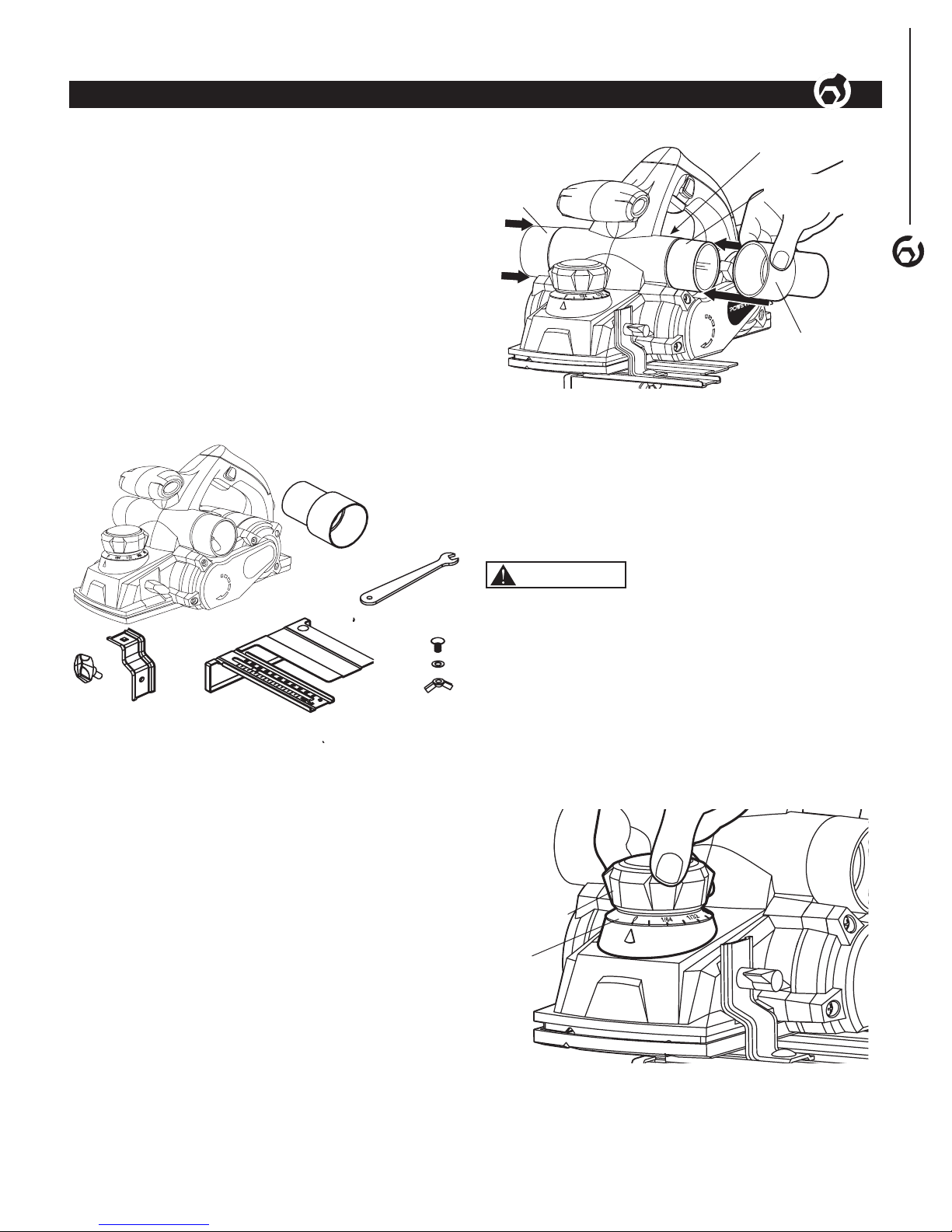
UNPACKING
Refer to Figure 1
• Examine shipping carton for freight damage before
opening. If shipping carton is damaged file a claim with
the carrier immediately.
• Carefully remove all contents from shipping carton. The
shipping carton contains:
1 - Planer
1 - Parallel Fence (bracket, bolt, washer, wingnut)
1 - Dust Extraction Adapter
1 - Locking Knobs
1 - Wrench
1 - Owner's Manual (not shown)
Planer
Parallel
Fence
Bolt
Washer
Wingnut
Locking
Knob
Figure 1
Dust Extraction
Adapter
Parallel
Bracket
Wrench
NOTE: Contact the customer service center if any of these
parts are missing.
NOTE: After unit is assembled dispose of all packaging
material in an environmentally safe way.
ATTACHING DUST EXTRACTION
(optional)
Refer to Figure 2
NOTE: A dust extraction adapter can be fitted to the
appropriate port to allow a dust extraction system or a
suitable vacuum cleaner to be connected to the tool for a
cleaner and safer work area.
• Rotate the extraction guide switch to the desired dust
extraction port.
• Attach the dust extraction adapter to the desired dust
extraction port
Attach the dust extraction system or a suitable vacuum
cleaner hose to the adapter.
Figure 2
Extraction
Guide Switch
Dust Extraction Port
Dust
Extraction
Port
Dust Extraction
Adapter
NOTICE: Shavings may jam the dust extraction port. DO
NOT place fingers inside the dust extraction port. Switch
off and unplug the planer from the power supply, wait for
the cutter to come to a complete stop before cleaning out
the dust extraction port.
ADJUSTING THE DEPTH OF CUTTING
Refer to Figure 3
WARNING
Turn switch OFF, remove the plug from the power source
outlet and wait until the blades have come to a complete
standstill before making any adjustments or removing or
installing accessories.
• Rotate the depth adjustment knob clockwise for a
deeper cut or counterclockwise for a shallower cut.
• The numbers on the depth adjustment scale indicate the
depth of cut. The minimum cutting increment is 1/128”
(0.2 mm).
Figure 3
Depth
Adjustment
Knob
Depth
Adjustment
Scale
NOTE: It is recommended to make test cuts into a scrap
piece of wood after each adjustment to ensure the desired
amount of wood is being removed. Making several shallow
cuts instead of one deep cut will create a smoother finish.
Page 6

ASSEMBLY
4
PARALLEL FENCE
Refer to Figure 4
WARNING
Turn switch OFF, remove the plug from the power source
outlet and wait until the blades have come to a complete
standstill before making any adjustments or removing or
installing accessories.
• Assemble the parallel fence to the bracket using
the bolt, washer and wingnut. The washer is placed
between the wing nut and parallel fence.
• Secure the parallel fence bracket to the left-hand side of
the planer with the locking knob.
• Loosen the wing nut and slide the parallel fence in or
out to the desired width. Tighten the wing nut.
Figure 4
Fence
Fence Bracket
Wing Nut
Bolt
Washer
Locking Knob
POWER SOURCE
WARNING
Do not connect to the power source until the machine is
completely assembled.
The machine is wired for 120 volts, 60 Hz alternating
current. Before connecting the machine to the power
source, make sure the switch is in the “OFF” position.
Running the unit on voltages which are not within range
may cause overheating and motor burn-out. Heavy loads
require that voltage at motor terminals be no less than the
voltage specified on nameplate.
GROUNDING INSTRUCTIONS
IN THE EVENT OF A MALFUNCTION OR BREAKDOWN,
grounding provides the path of least resistance for an
electric current and reduces the risk of electric shock.
This tool is equipped with an electric cord that has an
equipment grounding conductor and a grounding plug.
The plug MUST be plugged into a matching outlet that is
properly installed and grounded in accordance with ALL
local codes and ordinances.
DO NOT MODIFY THE PLUG PROVIDED. If it will not fit
the outlet, have the proper outlet installed by a licensed
electrician.
IMPROPER CONNECTION of the equipment grounding
conductor can result in electric shock. The conductor with
the green insulation (with or without yellow stripes) is the
equipment grounding conductor. If repair or replacement
of the electric cord or plug is necessary, DO NOT connect
the equipment grounding conductor to a live terminal.
CHECK with a licensed electrician or service personnel
if you do not completely understand the grounding
instructions or whether the tool is properly grounded.
CAUTION
In all cases, make certain the outlet in question is properly
grounded. If you are not sure, have a licensed electrician
check the outlet.
WARNING
This tool is for indoor use only. Do not expose to rain or
use in damp locations.
Guidelines for using extension cords
Make sure your extension cord is in good condition.
When using an extension cord, be sure to use one heavy
enough to carry the current your product will draw. An
undersized cord will cause a drop in line voltage resulting
in loss of power and overheating. The table below shows
the correct size to be used according to cord length and
nameplate ampere rating. When in doubt, use a heavier
cord. The smaller the gauge number, the heavier the cord.
AMPERAGE
REQUIRED GAUGE
FOR EXTENSION CORDS
25 ft. 50 ft. 100 ft. 150 ft.
6 A 18
gauge
16
gauge
14
gauge
12
gauge
Make sure your extension cord is properly wired and in
good condition. Always replace a damaged extension cord
or have it repaired by a qualified person before using it.
Protect your extension cords from sharp objects,
excessive heat and damp/wet areas.
Use a separate electrical circuit for your tools. This circuit
must not be less than a #12 wire and should be protected
with a 15 A time-delayed fuse. Before connecting the
motor to the power line, make sure the switch is in the
OFF position and the electric current is rated the same as
the current stamped on the motor nameplate. Running at
a lower voltage will damage the motor.
WARNING
This tool must be grounded while in use to protect the
operator from electric shock.
Page 7

OPERATION
5
SWITCHING ON AND OFF
Refer to Figure 5
CAUTION
Before connecting to the power supply, always make sure
the trigger switch and trigger lock work properly. The tool
is equipped with a trigger lock to avoid unintentional startups.
To turn the planer on, press the trigger lock and then
squeeze the trigger switch.
To switch off, release the trigger switch.
Figure 5
Trigger Lock
Trigger
TOOL PARK REST
Refer to Figure 6
When the planer is lifted from the workpiece the park rest
swings down to rest on the workpiece. This keeps the
blade from coming into contact with the work surface.
The tool park rest will swing up and out of the way when
the back of the planer crosses the edge of the workpiece.
Figure 6
Tool Park
Rest Up
Tool Park
Rest Down
Depth Adjustment
Knob/ Front Handle
Main Handle
CAUTION
DO NOT lock the trigger switch on when resting the
tool on the park rest. The vibration of the running motor
will cause the planer to move and possibly fall from the
workpiece.
PLANING
Refer to Figure 6
CAUTION
Always start the planer and allow it to reach full speed
before touching it to the the workpiece. Lift the tool from
the workpiece before releasing the trigger and turning
it off. Wait until the cutter has come to a complete stop
before setting the planer down.
• Ensure the workpiece is held securely in place on the
work surface.
• Hold the planer firmly with both hands, with one hand
on the depth adjustement knob/front handle and one
hand on the main handle. Rest the front shoe flat on the
workpiece surface, make sure the blades do not make
contact with the workpiece.
• Switch the tool on and wait for the blades to reach full
speed.
• Move the tool gently forward, applying downward
pressure to the front of the tool at the beginning of
planing and at the rear of the tool toward the end of the
planing stroke.
• Push the planer beyond the edge of the workpiece
without tilting it downwards. Do not stop the planer until
it clears the workpiece completely.
NOTICE: Planing is easier if you incline the workpiece
slightly away from you so that you plane “downhill”.
The rate of planing and the depth of the cut determine the
quality of the finish. For rough cutting, you can increase
the depth of cut. To achieve a good finish, you will need to
reduce the depth of the cut while advancing the tool more
slowly.
NOTICE: Moving the machine too fast may cause a poor
quality of cut and can damage the blades or the motor.
Moving the machine too slowly may burn or mar the cut.
The proper feed rate will depend on the type of material
being cut and the depth of the cut. Practice on a scrap
piece of material to gauge the correct feed rate and cutting
dimensions.
CAUTION
The motor may stall if improperly used or overloaded.
Reduce the pressure (feed rate) or depth of cut to prevent
possible damage to the tool if the motor labors.
OPERATION
5
Page 8

CHAMFERING
Refer to Figure 7
To make a chamfered cut, align the “V” grooves in the
front shoe of the planer with the corner edge of the
workpiece.
• Adjust to desired depth of cut.
• Place the “V” groove on the front adjustable shoe over
the edge being beveled. Place weight on the depth
adjustment knob so that the “V” groove is flat on the
edge to be beveled.
• Grasp the tool firmly with both hands. Turn the tool on
and push the plane forward with steady pressure on the
front adjustable shoe.
45°
Figure 7
Depth
Adjustment
Knob
"V" Groove
OPERATION
6
Otherwise, the resulting imbalance can cause vibration
and poor planing action while shortening the life of the
blade and the tool.
The planer blades are reversible. When one of the
cutting edges becomes dull or chipped the blade can be
reversed. When both cutting edges have been used the
blades should be discarded.
Do not attempt to sharpen or use resharpened blades of
any kind. Use only blades designated for use with this
model, as other blades may not clamp securely in blade
holder, causing vibration and a decrease in performance.
• Use the wrench supplied to loosen all clamping screws.
Figure 8
Clamping
Screws
• Clean chips and foreign matter from the cutter drum and
blade.
• If one blade edge is dull, reverse the blade. If both blade
edges are dull, remove the blade and replace it with a
new blade.
• Slide the good blade face up into the blade holder of the
cutter drum until it stops. The ridge along the blade goes
on the opposite side of the clamping screws.
Align Blade
• Loosely tighten the two outside clamping screws, the
blade must be adjusted to align with the outside edge
of the front and rear shoes.
MAINTENANCE
6
MAINTENANCE
6
WARNING
Any attempt to repair or replace electrical parts on this
tool may be hazardous. Repairs not listed here should be
performed by a qualified service technician.
WARNING
Always turn switch OFF, remove the plug from the power
source outlet and wait until the blades have come to a
complete standstill before making any adjustments or
removing or installing accessories.
• Replace any damaged or missing parts. Use parts list
to order parts. Any attempt to repair motor may create
a hazard unless repair is done by a qualified service
technician. Call the customer service line at 847-780-6120
for assistance.
REMOVING OR INSTALLING PLANER
BLADES
Refer to Figure 8–9
WARNING
Turn switch OFF, remove the plug from the power source
outlet and wait until the blades have come to a complete
standstill before making any adjustments or removing or
installing accessories.
WARNING
These blades cannot and should not be resharpened.
WARNING
The planer blades are sharp and fragile and must be
handled carefully to avoid injury to the user and damage
to the blades.
NOTICE: Always change both blades at the same
time. Use blades of the same dimensions and weight.
Page 9

times to make sure the belt is even on both pulleys.
• Replace the drive belt cover and secure in place with
the four screws. Tighten screws.
• Connect to the power supply and switch the planer on,
run for one minute to make sure the motor and new belt
work properly.
Figure 10
Drive Belt Cover
LUBRICATION
Your tool has been properly lubricated and is ready to use.
It is recommended that tools with gears be re-lubricated
with a special gear lubricant at every brush change.
CARBON BRUSHES
The brushes in your tool have been engineered for many
hours of dependable service. To maintain peak efficiency
of the motor, we recommend examining the brushes every
two to six months. Only genuine replacement brushes
designed specifically for your tool should be used.
BEARINGS
Bearings that become noisy (due to heavy load or
abrasive material cutting) should be replaced as soon as
possible to avoid overheating or motor failure.
CLEANING
Ventilation openings must be kept clean and free of
foreign matter. Do not attempt to clean these components
by inserting pointed objects through openings.
WARNING
The tool may be cleaned most effectively with compressed
dry air. Always wear safety goggles when cleaning tools
with compressed air.
WARNING
Certain cleaning agents and solvents damage plastic
parts. Some of these are: gasoline, carbon tetrachloride,
chlorinated cleaning solvents, ammonia and household
detergents that contain ammonia.
MAINTENANCE
7
MAINTENANCE
7
• Place a straight edge along the outside surface of the
front and rear shoes.
Figure 9
Front Shoe
Rear
Shoe
Blade
• Slide the blade until it contacts the straight edge.
• Make sure the blade sits correctly in the blade holder
groove of the cutter drum.
• Tighten the clamping screws.
CAUTION
Tighten all clamping screws carefully. A loose clamping
screw can be extremely dangerous. Check regularly to
ensure they are tightened securely.
NOTICE: Your planed surface will end up rough and
uneven unless the blades are properly and securely
set. The blades must be mounted so the cutting edge is
absolutely level (parallel to the surface of the rear shoe).
• Repeat for the second blade, making sure both blades
are set to the same cutting level and positioned in the
center of the cutter drum.
REPLACING THE DRIVE BELT
Refer to Figure 10
WARNING
Turn switch OFF, remove the plug from the power source
outlet and wait until the blades have come to a complete
standstill before making any adjustments or removing or
installing accessories.
• Remove the four screws from the drive belt cover.
• Remove the old drive belt. Pull the belt from the top
pulley while turning the bottom pulley by hand.
• Use a soft brush to clean the pulleys.
• Place the new belt on the bottom pulley first, align the
V grooves on the new belt with the grooves on the
bottom pulley. Place the other side of the belt onto the
top pulley, turn the top pulley by hand until the belt is
in place on both pulleys. Turn the pulley by hand a few
Page 10

5
TROUBLESHOOTING
8
8
TROUBLESHOOTING
SYMPTOM POSSIBLE CAUSE(S) CORRECTIVE ACTION
Motor does not run 1. Machine not plugged in 1. Plug power cord into electrical receptacle
2. Blown fuse or tripped circuit breaker 2. Replace fuse or reset the circuit breaker
3. Motor does not work 3. Replace motor
Motor stalls or
does not have full
power
1. Incorrect line voltage 1. Have a qualified electrician check circuit for proper voltage
Fuse blows or
circuit breaker trips
1. Overloaded electrical circuit breaker 1. Reduce the amount of items on circuit
2. Wrong fuse or circuit breaker 2. Replace with correct fuse or circuit breaker
3. Undersized or excessive length of
extension cord
3. Use correct size extension cord
Page 11

NOTE
Page 12

PLANER PARTS ILLUSTRATION
10
PARTS LIST
10
Page 13

PLANER PARTS LIST
11
Key No. Part No. Description Qty Specification Key No. Part No. Description Qty Specification
PARTS LIST
11
1 HP1005001 Screw 27 ST4.0x16
2 HP1005002 Belt cover 1 PA6-GF30
3 HP1005003 Bearing cover 1 PA6-GF30
4 HP1005004 Screw 4 ST4.2x10
5 HP1005005 Stator 1 φ73x50
6 HP1005006 Air deflection 1 PA6-GF30
7 HP1005007 Washer 2 4
8 HP1005008 Screw 2 ST4.0x65
9 HP1005009 Left handle 1 PA6-
GF30+TPE
10 HP1005010 Dust extraction panel 1 ABS
11 HP1005011 Dust extraction knob 1 ABS
12 HP1005012 Switch 1 DZKA-5 10A
250V
13 HP1005013 Cord clip 1 PA6-GF30
14 HP1005014 Cord guard 1 PVC
15 HP1005015 Power cord 1 2x1mm²
16 HP1005016 Driving wheel 1 LY12
17 HP1005017 Bearing 3 608-2RS
18 HP1005018 Armature 1 φ41x50
19 HP1005019 Nut 4 M6
20 HP1005020 Right housing 1 PA6-
GF30+TPE
21 HP1005021 Planer head 1 φ57.5x10⁸
22 HP1005022 Bearing 1 6200-2RS
23 HP1005023 Passive wheel 1 LY12
24 HP1005024 Belt 1 Rubber
25 HP1005025 Nameplate 1
26 HP1005026 Label 1
27 HP1005027 Foot park 1 PA6-GF30
28 HP1005028 Spring 1 65Mn
29 HP1005029 Supporting shaft 1 45#
30 HP1005030 Raffle plate 1 PA6-GF30
31 HP1005031 Base plate 1 ADC12
32 HP1005032 Guide plate 1 PA6-GF30
33 HP1005033 Spring 1 65Mn
34 HP1005034 ball 1 3.5
35 HP1005035 Screw 1 M6
36 HP1005036 Adjusting plate 1 ADC12
37 HP1005037 C-spring 1 65Mn
38 HP1005038 Regulating sleeve 1 ADC12
39 HP1005039 Adjust spring 1 65Mn
40 HP1005040 Main housing 1 PA6-GF30
41 HP1005041 Adjust nut 1 PA6-GF30
42 HP1005042 Dial 1 PA6-GF30
43 HP1005043 Adjust knob 1 ABS+TPE
44 HP1005044 Capacitor 1 2*0.22μF
45 HP1005045 Knob cover 1 ABS
46 HP1005046 Brush holder 2 H62Y2
47 HP1005047 Carbon brush 2 230V
48 HP1005048 Motor cover 1 PA6-GF30
49 HP1005049 Vacuum adapter 1 PA6-GF30
50 HP1005050
51 HP1005051 Fixing support 1 08F
52 HP1005052 Knob 1 PA6-GF30
53 HP1005053 Parallel guide 1 08F
54 HP1005054 Screw 1 M6x12
55 HP1005055 Wing nut 1 M6
56 HP1005056 Screw 2 ST4.0x30
57 HP1005057 Big washer 1 08F
58 HP1005058 Small washer 1 08F
59 HP1005059 Washer 1 6
60 HP1005060 Spanner 1 40Mn
Page 14

WARRANTY
12
WARRANTY
12
Thank you for investing in a POWERTEC power tool. This product has been designed and manufactured to meet high
quality standards and is guaranteed for domestic use against defects in workmanship or material for a period of 12
months from the date of purchase. This guarantee does not affect your statutory rights.
SOUTHERN TECHNOLOGIES LLC. BENCH TOP AND STATIONARY POWER TOOL
LIMITED 1 YEAR WARRANTY AND 30-DAY SATISFACTION GUARANTEE POLICY
POWERTEC products are designed and manufactured by Southern Technologies LLC. All warranty communications
should be directed to Southern Technologies LLC by calling 847-780-6120, 9 AM to 5 PM, Monday through Friday,
US Central Time.
30- DAY SATISFACTION GUARANTEE POLICY
During the first 30 days after the date of purchase, if you are dissatisfied with the performance of this POWERTEC tool
for any reason, you may return the tool to the retailer from which it was purchased for a full refund or exchange. You
must present proof of purchase and return all original equipment packaged with the original product. The replacement
tool will be covered by the limited warranty for the balance of the one year warranty period.
LIMITED ONE YEAR WARRANTY
This warranty covers all defects in workmanship or materials in this POWERTEC tool for a one year period from the
date of purchase. This warranty is specific to this tool. Southern Technologies, LLC reserves the right to repair or
replace the defective tool, at its discretion.
HOW TO OBTAIN SERVICE
To obtain service for this POWERTEC tool you must return it, freight prepaid, to POWERTEC. You may call
847-780-6120 for more information. When requesting warranty service, you must present the proof of purchase
documentation, which includes a date of purchase. POWERTEC will either repair or replace any defective part, at
our option at no charge to you. The repaired or replacement unit will be covered by the same limited warranty for the
balance of one year warranty period.
WHAT IS NOT COVERED
This warranty applies to the original purchaser at retailer and may not be transferred.
This warranty does not cover consumable items such as saw blades, knives, belts, discs, cooling blocks and sleeves.
This warranty does not cover required service and part replacement resulting from normal wear and tear, including
accessory wear.
This warranty does not cover any malfunction, failure or defect resulting from:
1) misuse, abuse, neglect and mishandling not in accordance with the owner’s manual.
2) damage due to accidents, natural disasters, power outage, or power overload.
3) commercial or rental use.
4) alteration, modification or repair performed by persons not recommended by POWERTEC.
DISCLAIMER
To the extent permitted by applicable law, all implied warranties, including warranties of MERCHANTABILITY or
FITNESS FOR A PARTICULAR PURPOSE, are disclaimed. Any implied warranties, that cannot be disclaimed under
state law are limited to one year from the date of purchase. Southern Technologies LLC. is not responsible for direct,
indirect, incidental or consequential damages. Some states do not allow limitations on how long an implied warranty
lasts and/or do not allow the exclusion or limitation of incidental or consequential damages, so the above limitations may
not apply to you. This warranty gives you specific legal rights, and you may also have other rights which vary from state
to state. Southern Technologies LLC., makes no warranties, representations, or promises as to the quality or
performance of its power tools other than those specifically stated in this warranty.
Page 15

NOTE
Page 16

Southern Technologies, LLC
3816 Hawthron CT,
Waukegan, IL 60087
 Loading...