

Page 1

Repair Center for Powertec Drives and Motors
460 Milford Parkway
Milford, OH . 45150
www.motorsystems.com
513-576-1725
Page 2
ADVANCED
MICROPROCESSOR CONTROLLED
DIGITAL SPEED / RATIO CONTROLLER
INSTALLATION AND OPERATION
MADE IN USA
This manual is fully implemented with software version (SFWVER)
93271 and later. See page 10 to find the software version of your
unit
INSTRUCTION MANUAL
Revision 2A
October 6, 1993
POWERTEC Publication # DGMAX4IM
Page 3

Page ii © copyright 1992-1996 by Powertec Industrial Motors
Page 4

DIGIMAX® Manual
Table of Contents
INTRODUCTION ....................................................................................................... 1
1.0 INSTALLATION ......................................................................................................... 3
1.1 CUSTOMER CONNECTIONS................................................................................... 3
2.0 ORIENTATION .......................................................................................................... 9
3.0 SET UP PARAMETERS .......................................................................................... 13
#1 Maximum Motor Speed............................................................................................ 15
#2 Maximum Display Value .......................................................................................... 15
#3 Decimal Places ........................................................................................................ 16
#4 Slave Ratio Setting .................................................................................................. 16
#5 Feedback PPR......................................................................................................... 16
#6 Acceleration Time.................................................................................................... 16
#7 Deceleration Time ................................................................................................... 17
#8 Master/Slave............................................................................................................ 17
#9 Preset Speed ........................................................................................................... 17
#10 Jump UP Change .................................................................................................... 17
#11 Jump Down Change ................................................................................................ 18
#12 Up-to-Speed Tolerance ........................................................................................... 18
#13 M.O.P./Jump ............................................................................................................ 18
#14 Freeze/Float ............................................................................................................ 18
#15 Display Sample Rate ............................................................................................... 18
#16 Setup During Run .................................................................................................... 18
#17 Unit I.D.....................................................................................................................19
#18 Baud Rate................................................................................................................ 1 9
#19 Local/Remote/Keylock............................................................................................. 1 9
#20 Speed/Ratio SETPOINT........................................................................................ 1 9
#21 Operator Security Code........................................................................................... 19
#22 A to D Low Engineering Units ................................................................................. 19
#23 A to D High Engineering Units ................................................................................ 2 0
#24 A to D Display Mode................................................................................................ 2 0
#25 A to D Sample Rate ................................................................................................. 20
#26 A to D Trim Enable .................................................................................................. 20
#27 Communications Protocol........................................................................................ 21
#28 D to A Source .......................................................................................................... 21
#29 D to A Low Engineering Units ................................................................................. 21
#30 D to A High Engineering Units ................................................................................ 2 1
#31 Maximum Ratio ........................................................................................................ 21
#32 PRESET Input Mode ............................................................................................... 21
#33 REVERSE Input mode............................................................................................. 22
#34 UP Input Mode......................................................................................................... 22
#35 DN Input Mode......................................................................................................... 22
#36 Installed Option Enable ........................................................................................... 22
#37 Command Ratio Setpoint......................................................................................... 22
#38 Maximum Command Ratio....................................................................................... 22
#39 Debounce Value ...................................................................................................... 22
#40 AT SPEED Source................................................................................................... 22
#41 Communications Turn Around Time........................................................................ 22
®®
®
®®
Manual
Revised 10/06/93
Page iiiDIGIMAX
Page 5

TABLE OF CONTENTS (continued)
4.0 SETUP AND OPERATION ...................................................................................... 23
LOCAL OR REMOTE .............................................................................................. 23
COMMAND OR ACTUAL ........................................................................................ 25
SETUP OR NORMAL .............................................................................................. 25
ERROR CODES ...................................................................................................... 27
JUMP OR MOP........................................................................................................ 30
FREEZE OR FLOAT................................................................................................ 3 1
MASTER OR SLAVE ............................................................................................... 31
Basic Master Mode setup ................................................................................... 31
Basic Slave Mode setup..................................................................................... 32
ADVANCED FUNCTIONS ....................................................................................... 33
List of Illustrations
1. Physical Dimensions ................................................................................................. 2
2. Rear Terminal Strip connections ............................................................................... 5
3. Connections to the
DIGIMAXDIGIMAX
DIGIMAX
DIGIMAXDIGIMAX
®
......................................................................................................................
4. Front panel Display. .................................................................................................. 9
5. Typical connections to Model 500........................................................................... 24
6. Typical connections to Non-regenerative control .................................................... 26
7. Standard connections to Regenerative control ....................................................... 28
8. Standard Connections to the MILLENNIUM® drive ................................................. 30
8
List of TABLES
1 Basic Parameters Table (1 to 21)............................................................................ 1 4
1A Extended Parameters Table (22 to 36) ................................................................... 2 0
2 Error Codes ............................................................................................................ 27
Page iv © copyright 1992-1996 by Powertec Industrial Motors
Page 6

WARNING!
THE DIGIMAX®AS SHIPPED FROM THE FACTORY OPERATES ON
115VAC POWER INPUT ONLY AT TB1 TERMINALS 1 AND 3.
230 VAC UNITS MAY BE OBTAINED BY SPECIAL ORDER, IN WHICH
CASE IT WILL HAVE A 230VAC NAMEPLATE AND STICKER.
DO NOT APPLY 230 VAC TO THE DIGIMAX® UNLESS YOU HAVE
CHECKED FOR THE PROPER CONNECTIONS.
NOTICE!
If you are replacing a DIGIMAX III with a
DIGIMAXDIGIMAX
DIGIMAX®, check TB2
DIGIMAXDIGIMAX
terminals 1,2, and 3 to be sure that there are no connections to these
terminals! These terminals weren't used on the DIGIMAX III, but they
are used internally on the
TIONS on TB2 terminals 1,2, and 3 when the
DIGIMAXDIGIMAX
DIGIMAX®. There should be NO CONNEC-
DIGIMAXDIGIMAX
DIGIMAXDIGIMAX
DIGIMAX® is used.
DIGIMAXDIGIMAX
®®
®
®®
Manual
Page vDIGIMAX
Page 7

SUMMARY OF WARRANTY AND DISCLAIMER
POWERTEC Industrial Motors, warrants the
DIGIMAXDIGIMAX
DIGIMAX® to be free from defects in materials and
DIGIMAXDIGIMAX
workmanship for a period of one year from the date of shipment from the factory, or, if purchased from an
authorized distributor or Original Equipment Manufacturer, not more than 18 months from the date of shipment
from the factory. Upon written notification to the factory of a possible defect in materials or workmanship,
POWERTEC will, at its sole option, repair or replace, at the factory, such defective parts as it deems necessary
to restore the unit to its original specifications.
There is no other warranty, express or implied, including fitness of purpose for the application intended.
This warranty does not cover accidental or intentional damage; physical or electrical misuse or abuse;
defective or incorrect installation; effects of the
DIGIMAXDIGIMAX
DIGIMAX® on other equipment or effects on the
DIGIMAXDIGIMAX
DIGIMAXDIGIMAX
DIGIMAX
DIGIMAXDIGIMAX
caused by other equipment; attempted use outside of specified ranges; or any other situation which is deemed
to be outside of the control of POWERTEC.
The user is responsible for the application of the product and/or the programming thereof.
Programs which attempt to use the communications capability of the
DIGIMAXDIGIMAX
DIGIMAX® are the responsibility
DIGIMAXDIGIMAX
of the user.
This warranty does not encompass any other claims, including, but not limited to, special, incidental, or
consequential damages.
This instruction manual has been assembled as a guide to the use of a POWERTEC product. It represents
the best efforts to compile and present the information herein. Such errors as may appear in no way affect the
above stated warranty. If mistakes of fact are found or suspected in this manual, please notify the factory or
your distributor at once.
®
Page vi © copyright 1992-1996 by Powertec Industrial Motors
Page 8

®®
®
®®
Manual
Page viiDIGIMAX
Page 9

INTRODUCTIONINTRODUCTION
INTRODUCTION
INTRODUCTIONINTRODUCTION
DIGIMAXDIGIMAX
The
DIGIMAX® is an advanced, micro-processor based, digital speed reference
DIGIMAXDIGIMAX
designed for use with POWERTEC Brushless motors and controls. It is a reliable and
repeatable pulse train source with features designed for the needs of computer controlled
process lines. It may be used for master speed setting or as an extremely accurate ratio
setting device.
DIGIMAXDIGIMAX
The
DIGIMAX® is an "open loop" type of control, i.e., speed feedback information
DIGIMAXDIGIMAX
to this speed setting device is not necessary to maintain the speed regulation of the
system. The nature of the permanent magnet based Brushless motor and control system
is that it will maintain zero percent speed regulation from no load to full load over its entire
speed range. Closing the speed loop for speed regulation is unnecessary. Speeds
generated by the
operating conditions. The Brushless motor will run at exactly the speed at which it is told
to run, and the next time that same speed is commanded, it will be repeated exactly.
DIGIMAXDIGIMAX
The
DIGIMAX® is as much at home in the ratio mode as it is in the speed mode,
DIGIMAXDIGIMAX
and it can switch between the two on the fly. This consistent speed control is invaluable
in setting up processes which vary from day to day, but must be duplicated from order
to order.
DIGIMAXDIGIMAX
The
DIGIMAX® is also easy to apply and use. It can be installed in locations where
DIGIMAXDIGIMAX
it is easily accessible to operators, which may be remote from the location of the motor
control. Control inputs and outputs are isolated, for flexibility and immunity to interactions
between units.
Speed or ratio setpoints and operating parameters are entered via a 16-key keypad
on the face of the
entered by remote connection to an industry standard RS-422 or RS-485 communications link with a variety of protocols.
The five place digital readout may be set for motor RPM, process speed, or other
useful engineering units, from the motor or from another source besides the motor being
controlled. Indicators show when the speed is attained and whether the unit's control is
local or remote.
DIGIMAXDIGIMAX
The
DIGIMAX® has six programmable output switches (open collector transistors),
DIGIMAXDIGIMAX
offering the possibility of operation completely through the communications link.
There is a position registration function (temporary increase or decrease in speed)
which may be alternatively programmed as a motor operated potentiometer. There are
UP and DOWN controls are on the front panel, and there are remote inputs for these
functions as well. The MOP function may be programmed to stay at its former speed after
a stop, or to return to zero speed when stopped.
DIGIMAXDIGIMAX
DIGIMAX® represents a high level of sophistication for users of POWERTEC
DIGIMAXDIGIMAX
Brushless motors and controls. It is very effective in operator controlled or computer
controlled systems when precision, repeatability, flexibility, and ease of interface to the
host unit are required.
DIGIMAXDIGIMAX
DIGIMAX® are accurate within 50 parts per million under all specified
DIGIMAXDIGIMAX
DIGIMAXDIGIMAX
DIGIMAX®. Speed or ratio setpoints and parameters may also be
DIGIMAXDIGIMAX
DIGIMAX® is a registered trademark of POWERTEC Industrial Corporation
®®
®
®®
Manual
Page 1DIGIMAX
Page 10
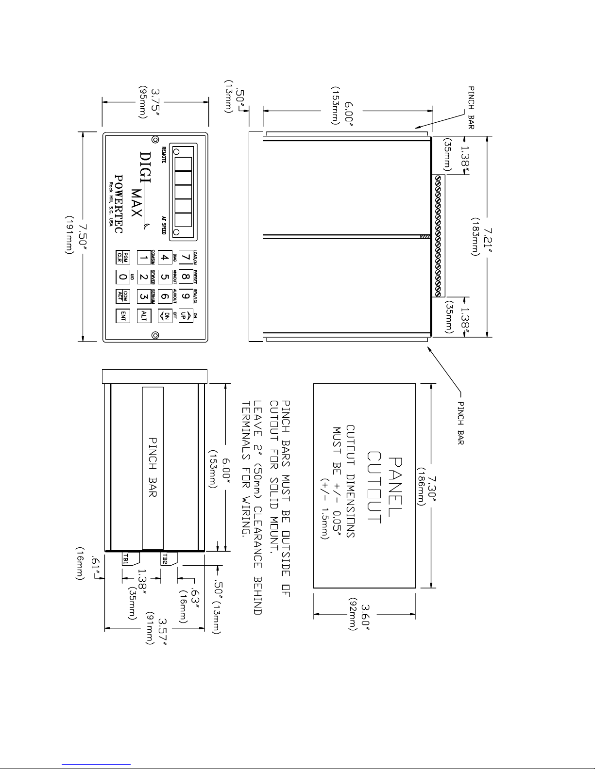
Figure 1: Physical dimensions of the DIGIMAX®.
Page 2 © copyright 1992-1996 by Powertec Industrial Motors
Page 11

1.0 INST1.0 INST
1.0 INST
1.0 INST1.0 INST
DIGIMAXDIGIMAX
The
DIGIMAX® may be installed in any orientation in a clean, dry location. Care should
DIGIMAXDIGIMAX
be exercised in making the cutout in the mounting panel, since the pinch bars must be placed
firmly against the mounting panel just outside of the cutout section to hold the unit in place.
The front panel has sealed membrane switches, but the front panel should be protected
against moisture falling directly onto it and seeping into the box around the faceplate.
The front panel should be protected against physical damage, but accidental casual
contact with the front panel is not likely to cause a problem.
The customer connection terminals at the rear of the box require at least 2" (50mm) of
free space behind the box for installation, removal and wiring. It is advisable to not install
high energy switches or electro-magnetic devices next to the
to run wires carrying high energy in the same groupings as the wires to and from it.
1.1 CUSTOMER CONNECTIONS1.1 CUSTOMER CONNECTIONS
1.1 CUSTOMER CONNECTIONS
1.1 CUSTOMER CONNECTIONS1.1 CUSTOMER CONNECTIONS
DIGIMAXDIGIMAX
The
DIGIMAX® has two terminal strips on the back of the unit for customer connections
DIGIMAXDIGIMAX
(see figure 2 on page 5). These terminal strips are removable for ease of wiring and to
facilitate the replacement of the unit, should that become necessary for any reason. The
terminal strips are keyed differently to prevent mix-ups.
All connections except the AC input power are low voltage, low current, DC circuits
which may be susceptible to system electrical noise interference. Directions for wiring and
shielding must be followed exactly for best results (see figure 3 on page 8).
Wires to and from the
All relays used in conjunction with, or in the vicinity of, the DIGIMAX® must have arc
suppressors (if they have AC coils) or free wheeling diodes (if they are DC). Keep high power
switching relays and contactors away from the
interference from arcing and magnetic field fluxes.
ALLAALLA
ALLA
ALLAALLA
DIGIMAXDIGIMAX
DIGIMAX
DIGIMAXDIGIMAX
TIONTION
TION
TIONTION
DIGIMAXDIGIMAX
DIGIMAX®, nor is it advisable
DIGIMAXDIGIMAX
®®
®
®®
must be kept away from power wiring.
DIGIMAXDIGIMAX
DIGIMAX® and its wiring to prevent
DIGIMAXDIGIMAX
BOTTOM TERMINAL STRIP TB1BOTTOM TERMINAL STRIP TB1
BOTTOM TERMINAL STRIP TB1
BOTTOM TERMINAL STRIP TB1BOTTOM TERMINAL STRIP TB1
1 115 VAC HOT line
2 unconnected pin
3 115 VAC NEUTRAL
4 CASE GROUND
5 EARTH GROUND
The DIGIMAX® must be operated on 115VAC, single phase. Tolerance is +/- 10%.
Frequency range is 48 to 62 hertz. If one side of the supply is grounded, the hot side of the
supply should be connected to terminal 1. The other wire is connected to terminal 3.
230VAC
of 230VAC power is discouraged due to the noisy nature of this type of power.
Terminal 2 is not connected to anything. It is used for voltage separation on the
terminals. Do not make connections of low-voltage, noise sensitive signals on terminal 2.
Terminal 4 is used for grounding the metal case of the
mounting screws, and terminal 5 should be solidly grounded to an earth ground. The earth
ground must be tied to a system ground which is tied into the system power ground at a
central location. Where long and (electrically) noisy runs are involved, an earth ground rod
in the vicinity of the drive cabinet is recommended.
The AC supply should not have excessive line noise. The input power to the unit is
filtered, but excessive line gaps or spikes could cause erratic power supplies.
®®
®
®®
Manual
DIGIMAXDIGIMAX
DIGIMAX® units may be obtained on special order from the factory. The use
DIGIMAXDIGIMAX
DIGIMAXDIGIMAX
DIGIMAX® with one of the case
DIGIMAXDIGIMAX
Page 3DIGIMAX
Page 12

6 10 -> 12 VDC output, unregulated, 100 mA
7 24 VDC output, unregulated, 100 mA
8 NO CONNECTION
9 NO CONNECTION
If you have an application where you wish to use DC power to power a
DIGIMAXDIGIMAX
DIGIMAX®,
DIGIMAXDIGIMAX
you must either use a UPS or contact POWERTEC for a special unit.
Terminal 6 may be used for small 12VDC loads up to 100 mA.
Terminal 7 can supply up to 50 mA at 20 to 24 VDC, unregulated. Terminal 7 is most
often used to turn on the DIGITAL mode in the Model 1000 series and larger drives (using
the 141-108 series Current Controller board), and this is, in fact, recommended.
The output level of these two terminals is dependent on the AC supply voltage.Other
loads on the unit and the load on each of these terminals will also affect the voltage level.
If either of these terminals are overloaded, the accuracy of the
DIGIMAXDIGIMAX
DIGIMAX® will be degraded.
DIGIMAXDIGIMAX
Terminal 4 or 5 may be used as a common for these terminals.
Voltage levels on terminals 6 and 7 ARE NOT GUARANTEED. These outputs are
for convenience only for small loads associated with the
DIGIMAXDIGIMAX
DIGIMAX®. If stable and/or
DIGIMAXDIGIMAX
regulated voltages are needed for external relays and devices used for system purposes,
the user should incorporate in the system a separate power supply for them.
10 - FREQUENCY OUTPUT
11 + FREQUENCY OUTPUT
This is the output frequency to the controlled drive or drives. It is capable of driving up
to ten inputs of motor controls or ten other
DIGIMAXDIGIMAX
DIGIMAX® inputs or a combination of the two
DIGIMAXDIGIMAX
adding up to ten inputs. Output from these terminals is a square wave from a "totem-pole"
driver with a +24 VDC peak and an off value less than 0.5 VDC. The duty cycle may vary.
12 - ANALOG OUTPUT
13 + ANALOG OUTPUT
The analog output at TB1 terminals 12 and 13 may be used to read a voltage signal
proportional to one of the
DIGIMAXDIGIMAX
DIGIMAX® speed sources, or from the RS-422 link, or from the
DIGIMAXDIGIMAX
keypad. This output ranges from 0 to +10 VDC. The source and level of this output is set by
parameters #28 (source of the output signal), #29 (the lowest value for the output), and #30
(the highest value for the output). See page 21.
14 EMITTERS OF AUXILIARY OUTPUTS
15 "AT SPEED" OUTPUT (open collector)
16 AUXILIARY OUTPUT #1 (open collector)
17 AUXILIARY OUTPUT #2 (open collector)
18 AUXILIARY OUTPUT #3 (open collector)
19 AUXILIARY OUTPUT #4 (open collector)
20 AUXILIARY OUTPUT #5 (open collector)
21 AUXILIARY OUTPUT #6 (open colllector)
22 OUTPUTS SUPPLY CONNECTION
An external power supply MUST be used to power any devices connected to
these outputs. These outputs are "open collector" outputs with all of the emitters brought
together at TB1 terminal 14 (see figure 2). The positive side of the supply has to be connected
to TB1 terminal 22 (this supplies the drivers on the board), and the negative side of the supply
must be connected to TB1 terminal 14. All of these outputs are isolated from the DIGIMAX
Page 4 © copyright 1992-1996 by Powertec Industrial Motors
®
Page 13
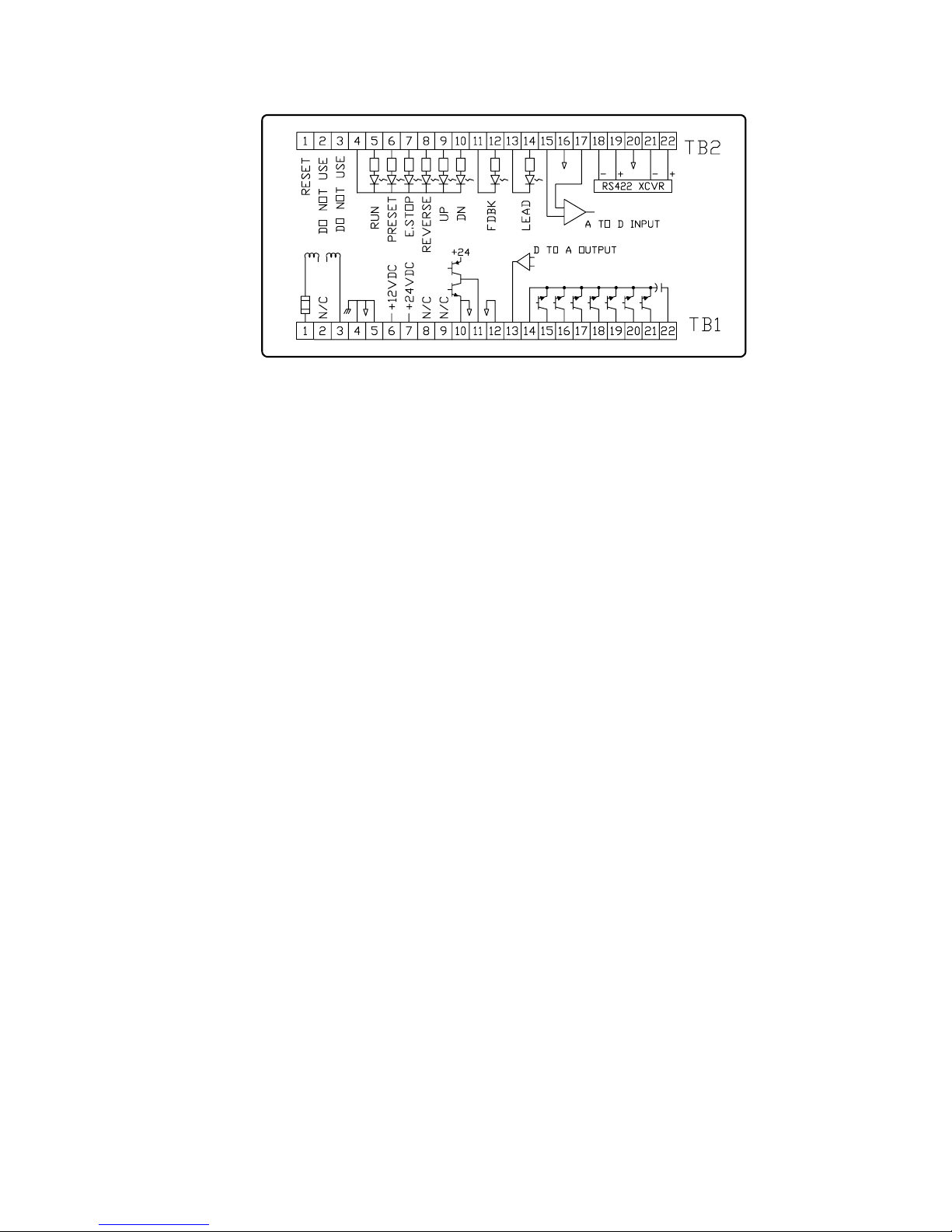
Figure 2: Rear terminal strip connections of the
DIGIMAXDIGIMAX
DIGIMAX
DIGIMAXDIGIMAX
®
common, but their emitters are all common to each other. The maximum allowable voltage
between TB1 terminals 22 (+) and 14 (-) is 30VDC. The maximum allowable current on each
of the TB1 terminals 15 thru 21 is 100 mA. Snubber diodes are built into the outputs. If the
wiring to the external relays is run more than a few feet, additional snubber diodes should
be used at the external relay coils.
Do not run any large solenoid valves or large contactors directly from these outputs.
Use interface relays connected to these outputs to run this other equipment.
The AT SPEED output operates with the AT SPEED indicator on the front panel. The
adjustment of the AT SPEED tolerance is controlled by parameter #12. The AT SPEED
output and the AT SPEED front panel LED work only in the MASTER mode. In SLAVE mode,
the AT SPEED LED and the AT SPEED output are on all of the time, except when changing
to a newly entered ratio..
The other six outputs are controllable by protocol commands through the RS-422 link.
They can also be operated from the keypad on the front (see page 11). These outputs may
be used for run, stop, man/auto, fwd/rev, or for peripheral device control.
By connecting relays to these outputs and using the relays to control the drive, it is
possible to run the
TOP TERMINAL STRIP TB2TOP TERMINAL STRIP TB2
TOP TERMINAL STRIP TB2
TOP TERMINAL STRIP TB2TOP TERMINAL STRIP TB2
DIGIMAXDIGIMAX
DIGIMAX® and motor control entirely through the communications link.
DIGIMAXDIGIMAX
1 HARDWARE RESET
2 DO NOT USE!
3 DO NOT USE!
Terminal 1 on TB2 is used for a hardware reset. When terminal 1 is connected to a
ground (such as TB1 terminal 5), the DIGIMAX® resets just as if the power to the unit were
turned off and the power was then turned back on again. The parameters are NOT cleared
by this operation.
It is NOT recommended that wires be permanently attached to these terminals
because there is a possibility that a noise pulse or accidental activation of the switch may
cause an unintentional reset, interrupting normal operation. Such noise may come from
nearby power components or a difference in potential between the case or terminals of the
DIGIMAXDIGIMAX
DIGIMAX® and ground.
DIGIMAXDIGIMAX
DO NOT MAKE ANY CONNECTIONS TO TB2 TERMINALS 2 and 3! These terminals
are used for programming functions. Connecting anything to these inputs will result in
damage to the unit.
®®
®
®®
Manual
Page 5DIGIMAX
Page 14

4 CATHODES OF CONTROL INPUTS (ground or common)
5 RUN INPUT (+24 VDC)
6 PRESET INPUT (+24 VDC)
7 EMERGENCY STOP INPUT (+24 VDC)
8 REVERSE INPUT (+24 VDC)
9 JUMP/MOP UP INPUT (+24 VDC)
10 JUMP/MOP DOWN INPUT (+24 VDC)
Power for the control inputs must be supplied from a separate source. Usually this
power comes from the Brushless drive being controlled. Nominal supply voltage is 24 VDC,
which need not be regulated, but must be filtered. The tolerance is +/- 25%.
The control inputs do not control any functions on the controlled drive. Commands
given to the
DIGIMAXDIGIMAX
DIGIMAX® must also be given to the drive at the same time.
DIGIMAXDIGIMAX
The EMERGENCY STOP input must be activate before the unit will respond to any
external input or keyboard commands. This input normally parallels the E.STOP of the drive.
Activating the RUN input starts the DIGIMAX®, and will it run until the RUN input is
removed. Usually, the run relay contact on the speed board of the drive is used for this. A
SETPOINT value should be entered prior to the first time a RUN command is entered after
power is applied; otherwise the unit will start at zero speed (or ratio) and wait for a SETPOINT
to be entered by the operator. If parameter #14 is set to 1 (see page 18), on all subsequent
RUN commands, the DIGIMAX® will start at the last speed or ratio entered.
The PRESET command changes the speed output to go to the value in parameter #9.
The REVERSE input causes the frequency output to decelerate, at the rate set into
parameter #7, to zero speed, and then to accelerate back to the setpoint at the rate set into
parameter #6. Giving a reverse command to the
DIGIMAXDIGIMAX
DIGIMAX® does NOT cause the drive to
DIGIMAXDIGIMAX
reverse. A separate, simultaneous command must be given to the drive. If the drive is given
a reverse command, it will not reverse until the
DIGIMAXDIGIMAX
DIGIMAX® is given a reverse command,
DIGIMAXDIGIMAX
because the drive input frequency must be at zero before the drive will reverse direction.
The JUMP/MOP UP and JUMP/MOP DOWN inputs duplicate the functions of the UP
and DN inputs on the front panel.
11 - TACHOMETER INPUT
12 + TACHOMETER INPUT
13 - FOLLOWER INPUT
14 + FOLLOWER INPUT
These two inputs are isolated from the
DIGIMAXDIGIMAX
DIGIMAX® electronics and from each other.
DIGIMAXDIGIMAX
Both inputs require a +24VDC nominal peak input and a low of less than 1VDC. Both inputs
will accept signals up to 50 kilohertz. Minimum pulse width for both inputs is 10 microseconds. Wider pulse widths are desireable. Rise times are not critical, but they should be less
than 5% of the duty cycle.
The tachometer input is for the
DIGIMAXDIGIMAX
DIGIMAX® display and it also supplies a zero speed
DIGIMAXDIGIMAX
signal. It normally comes from the motor control, but it may come from any frequency
reflecting the driven process. With a 1750 RPM small frame motor, a standard POWERTEC
Brushless motor control supplies a 3500 Hertz pulsed waveform to this input, but larger
motors' controls supply a 7000 hertz signal to the tachometer input and servo rated controls
may supply frequencies of up to 50 kilohertz.
The follower input is the frequency which the
DIGIMAXDIGIMAX
DIGIMAX® follows in SLAVE mode. A
DIGIMAXDIGIMAX
standard 1750 RPM low horsepower Brushless motor control operates at 3500 Hertz input
frequency. This is the ideal input frequency for the follower input if the follower motor is 1750
RPM. The
DIGIMAXDIGIMAX
DIGIMAX® can multiply by a factor of up to eight, but performance and resolution
DIGIMAXDIGIMAX
at high multiples may be degraded.
Page 6 © copyright 1992-1996 by Powertec Industrial Motors
Page 15

15 - AUXILIARY ANALOG INPUT
16 GROUND
17 + AUXILIARY ANALOG INPUT
The maximum input is +10 VDC, but the input is a differential type input, so a negative
voltage may be accepted by reversing input leads. TB2 TERMINAL 17 MUST ALWAYS BE
MORE POSITIVE (ON AN ABSOLUTE SCALE) THAN TB2 TERMINAL 15. If TB2 terminal
15 is more positive than TB2 terminal 17, the effective input will be 0.
The auxiliary analog input is for transferring an analog voltage representing a system
value (such as motor current) through the RS-422 communications link. For this type of
operation, parameter #26 must be 0. #23 is set to read out a +10 VDC input in Engineering
Units (EGU). Parameter #22 is set to low EGU, which may be zero, but doesn't have to be.
The auxiliary analog input may also be used as an analog trim or dancer (see
parameters #20 on page 19, and #26 on page 21). The input leads should be connected to
TB2 terminals 15 and 17 (not ground) and TB2 terminal 16 should be used for the shield.
If parameter #26 is 1, a 5VDC input is zero effect. Increasing voltage increases the setpoint.
If parameter #26 is 2, a 0VDC input is no effect. Increasing voltage increases the setpoint.
If parameter #26 is 3, a 0VDC input is no effect. Increasing voltage decreases the setpoint.
The maximum speed (parameter #1) may not be exceeded in speed mode.
The maximum ratio (parameter #31) may not be exceeded in slave mode.
18 RS-422 - RECEIVE
19 RS-422 + RECEIVE
20 RS-422 No connection
21 RS-422 - TRANSMIT
22 RS-422 + TRANSMIT
In order to ensure good communications, it is required that shielded cable be used in
the RS-422 communications link. The cable should have conductors no smaller than #24
AWG for distances up to 500 feet. Recommended cables are cables such as Belden® Wire
Company part #9829 or part #88102.
Connecting the link together consists of connecting all of the transmit terminals of the
DIGIMAXDIGIMAX
DIGIMAX® units in parallel (+ to +, and - to -). Then all receive terminals are connected in
DIGIMAXDIGIMAX
parallel (+ to +, and - to -).
ANSI standards apply to RS-422 communications. The RS-422 standard stipulates
that the number of stations shall be at least 10 without repeaters. (Repeaters are amplifiers
which strengthen the signal to feed more stations). The
DIGIMAXDIGIMAX
DIGIMAX® communications may
DIGIMAXDIGIMAX
operate up to 32 units on the link.
After connecting all of the RS-422 terminals together, one end of the chain is tied to the
host (a PLC, a personal computer through an RS-422 output card or an RS-232 to RS-422
converter, or an industrial computer with an RS-422 port). Normally the "transmits" of the
DIGIMAXDIGIMAX
DIGIMAX®'s will tied to the "recieve" of the host, and the "receives" to the "transmits", but
DIGIMAXDIGIMAX
check the specifications of the host to be used. The unit at the far end of the line, furthest from
the host, must have a resistor equal to the cable's impedance (120 ohms) installed across
its receive terminals. This is "terminating" the line. It prevents signal reflections from causing
spurious signals on the line. The transmit line is terminated at the host.
The RS-485 Communications standard may be used with the
DIGIMAXDIGIMAX
DIGIMAX® by tying the
DIGIMAXDIGIMAX
+Transmit to the +Receive and the -Transmit to the -Receive. Terminal 20 is for the shields.
If you are putting together a large system, it is a good idea to consult someone who is
knowledgable and experienced in the art of serial communications.
®®
®
®®
Manual
Page 7DIGIMAX
Page 16

Figure 3: Connections to the DIGIMAX® speed controller.
Page 8 © copyright 1992-1996 by Powertec Industrial Motors
Page 17

2.0 ORIENT2.0 ORIENT
2.0 ORIENT
2.0 ORIENT2.0 ORIENT
AA
TIONTION
A
TION
AA
TIONTION
The proper operation of the
panel controls. Speeds, ratios, and parameters will be set by the operator with the keypad,
which consists of numerical and action keys. The display and the LED's will supply important
information during setup and while the process is in operation.
Figure 4: Front panel display
The display is a full five digits, allowing numbers up to 99999 to be displayed. A decimal
point may be placed between any two of the five digits, allowing numbers to be displayed
or set down to 0.0001.
The display has two levels of brightness to indicate the mode in which it is operating.
The COMMAND mode is a dimmer display. In COMMAND mode the display shows the
SETPOINT value. The ACTUAL mode is a much brighter display. In ACTUAL mode the
display shows the actual speed of the motor in whatever scale is set up by the parameters.
See the explanation of the COM/ACT button below.
The AT SPEED indicator changes only in the MASTER mode, indicating that the actual
motor speed is within the programmed tolerance. In SLAVE mode the AT SPEED indicator
is on all of the time except when slewing to a newly entered ratio.
The REMOTE indicator is on when remote operation is on. In one REMOTE mode, the
keypad is locked out unless the unit's LOC/REM key is pressed. In another mode, even the
LOC/REM key is locked out.
DIGIMAXDIGIMAX
DIGIMAX® requires a complete understanding of the front
DIGIMAXDIGIMAX
The numeric display of the
while power is applied. There are, however, times at which the
display will be blank. One condition under which the display
blanks while power is on is when the PGM/CLR button is pressed
just prior to entering the access code. The access code may then
be entered. Another occasion when the display goes blank is after
the ALT key is pressed until one of the keys with a command in
small letters above it is pressed.
DIGIMAXDIGIMAX
DIGIMAX® is normally lit up
DIGIMAXDIGIMAX
THRU
The number keys on the
1. entering speeds and ratios into the unit while the unit is in operation. Speeds and
ratios may range from one to five digits, from 0.0001 to 99999;
2. entering the security code to gain access to the parameters. The security code may
vary from 1 to 5 digits. It is not necessary to enter leading zeroes;
3. entering parameter values while in setup mode. The parameter values may range
from one to five digits.
DIGIMAXDIGIMAX
The
DIGIMAX® will not accept more than five digits in a single number. When a
DIGIMAXDIGIMAX
number is pressed, the microprocessor enters the number entry mode. As numbers are
entered, they are displayed in the display (except in the entry of security codes, when dashes
are displayed). On the sixth consecutive digit a new five digit number is started. This feature
may be used to advantage when an incorrect number is pressed during an entry. Simply
keep pressing numbers until the display is full, then enter the correct number sequence.
The ENTER button must be pressed before any numerical data is entered into the
DIGIMAXDIGIMAX
DIGIMAX®. Numbers may be pressed continuously, but nothing will happen until the
DIGIMAXDIGIMAX
ENTER button is pressed. The ENTER button must be pressed after the security code, after
speed or ratio command entries, and after parameter values are entered. The ENTER button
is not used for function keys such as UP, DN, SET, COM/ACT, or LOC/REM.
The ENTER key may also be used to clear error codes (see page 27).
®®
®
®®
Manual
DIGIMAXDIGIMAX
DIGIMAX® are used for :
DIGIMAXDIGIMAX
Page 9DIGIMAX
Page 18

The UP and DN buttons are used to make changes in the speed or ratio while the
DIGIMAXDIGIMAX
DIGIMAX® is in operation. There are two control inputs on the back terminals which
DIGIMAXDIGIMAX
accomplish the same functions as the front panel buttons.
There are two modes of response to the UP and DN buttons (see page 31):
1. A "shaft position change" (JUMP) function. When the UP or DN button is pressed,
the output frequency temporarily increases or decreases (depending which one is pressed)
and returns to the SETPOINT when the button is released. The effect of this on the Brushless
motor control is to move the motor shaft forward or backward in its rotation by an amount
proportional to the extra pulses. The amount of change is determined by parameters.
2. A "motor operated potentiometer" (MOP) function. When the UP or DN button is
pressed, speed will continue to increase or decrease as long as the appropriate button is
pressed. When the button is released, speed will remain at the value which exists when the
button is released. This emulates the action of the traditional motor operated potentiometer.
The UP and DN buttons are also used during parameter entry (see page 13).
The CMD/ACT button toggles the
DIGIMAXDIGIMAX
DIGIMAX® between displaying the speed (or ratio)
DIGIMAXDIGIMAX
COMMAND value and the ACTUAL speed (or a derivative thereof). In ACTUAL mode (the
display is bright) the microprocessor displays the speed information returned by the motor.
In COMMAND mode (the display is dimmed) the display is the current SETPOINT (a speed
command in MASTER mode and a ratio command in SLAVE mode). In SLAVE mode a
decimal point appears after the first digit to show how many numbers to enter (see page 34).
The PGM/CLR key is used to enter and leave the parameter table in the SETUP mode.
It must be pressed first, followed by a security code and then the ENTER button to access
the parameters. When the PGM/CLR key is pressed, the display will blank and the numbers
of the security code, as they are entered, will be acknowledged by a dash for each number
pressed. After the ENTER button is pressed, if the code is correct, the display will show the
parameter which was displayed when the parameters were last accessed, or parameter #1
if this is the first access since the last power-up. The PGM/CLR key must be pressed to exit
the SETUP mode. If the access code is incorrect, the display returns to the mode it was in
before the PGM/CLR key was depressed.
The PGM/CLR key may also be used as a CLEAR function during value entry.
The ALT key is used for quick access to command functions which are assigned to the
number and command keys as ALTernate functions. These are functions which may not be
used as often as the dedicated keys, but to which quick access is desired. To use the
alternate functions, it is necessary to press the ALT key (the display will go blank), and then
the key with the desired function printed above it. In some cases, additional actions may be
necessary.
UID The UID function displays the Unit ID number (param #17) when the ALT key is
pressed, followed by the "0" key. After 10 seconds, the display returns to its previous state.
COMSIM COMSIM means COMmunications SIMulator. The COMSIM function sends
out a continuous string of "A" characters (hex 41) on the RS-422 port for 10 seconds. This
function is used for testing. It is accessed by pressing the ALT key followed by the "1" key.
SFWVER To accommodate changes in function of the DIGIMAX
EEPROM may be changed. Sometimes it is necessary to refer to the specific software in the
unit. Pressing ALT followed by the "2" key makes the version date appear in the display. The
format of the date is a five digit number. The first two numbers are the year and the last three
numbers are the day of the year. For instance, April 10th is the 100th day of a non-leap year.
Page 10 © copyright 1992-1996 by Powertec Industrial Motors
®
, the software in the
Page 19

SERNUM Pressing ALT followed by the "3" key displays the serial number of the unit.
DIAG The DIAGnostics function will display a set of diagnostic aids to help to determine
the state of the
to use the diagnostic functions.
Pressing ALT followed by the "4" key causes an equals sign ("=") to appear in the left
lower corner of the display.
If the "1" button is then pressed, a two digit HEX number appears in the display which
represents the on/off states of the inputs on terminals 4 through 10 on TB2.
The number may range from "00" (all inputs off) to "3F" (all inputs on). The number "05"
in the display would tell the operator that the RUN and ESTOP inputs are on, and therefore
DIGIMAXDIGIMAX
the
DIGIMAX® should be running.
DIGIMAXDIGIMAX
This number is structured as follows:
DIGIMAXDIGIMAX
DIGIMAX®. You must have a knowledge of how to use hexadecimal numbers
DIGIMAXDIGIMAX
The first digit is bits 4-7 (7654 binary).
The second digit is bits 0-3 (3210).
bit 7 = Not used
bit 6 = Not used
bit 5 = Down input
bit 4 = Up input
bit 3 = Reverse input
bit 2 = EStop input
bit 1 = Preset input
bit 0 = Run input
If the "DOWN" input (not the front panel key) is activated while running, the number
displayed should be "23" (0010 0011).
ANAOUT Pressing the ALT key and the "5" key displays the current value of the
Analog Output at terminals 13 (+) and 12 (-) on TB1.The display shows the letter "Ao" on the
left side of the display and the current value of the Analog Output in Engineering units, which
are controlled and scaled with parameters #28 through #30. (See parameters section).
Parameter #28 determines the source of the Analog Output signal and parameters #29
and #30 determine the minimum and maximum values, respectively. If parameter #28 is set
to "3", the Analog output value is set from the keypad. Simply key in a new number between
parameter #29 (0 VDC out) and parameter #30 (10 VDC out) and press ENT. The Analog
Output will go a the new value which is proportionally between the two.
AUXOUT Pressing the ALT key and the "6" key brings up the AUXiliary OUTput menu.
The letters "Au" appear on the left side of the display. You can see the state of one of the
six auxiliary outputs by pressing the output number (1 through 6). If you then wish to change
the state of the output, you can press either the ON (UP) key or the OFF (DN) key and then
the ENT key to change the state of the output.
LOAD/AI The value in engineering units of the Analog Input (TB2 terminals 15 and 17)
is displayed by pressing the ALT key followed by the "7" key. An "Lo" is displayed followed
by the value. Scaling is handled by parameters #22 and #23 (see parameters section).
PRESET The
ALT key followed by the "8" key followed by the "UP" (ON) key. To turn the PRESET off,
press ALT, then the "8" key, then the "DN" (OFF) key.
DIGIMAXDIGIMAX
DIGIMAX® may be forced into PRESET speed mode by pressing the
DIGIMAXDIGIMAX
®®
®
®®
Manual
Page 11DIGIMAX
Page 20

REM/LCL Press the ALT key followed by the "9" key to toggle between the Remote and
Local modes of the
all keypad functions are active. In Remote mode only the REM/LCL function and the COM/
ACT key will operate. If parameter #19 is set to "2" (KEYLOCK), you must press the ALT key,
an access code, the UP key and the ENT key in sequence before the
back to the Local mode from the KEYLOCK mode.
DIGIMAXDIGIMAX
DIGIMAX®. In Local mode (REMOTE LED indicator in the display is off)
DIGIMAXDIGIMAX
DIGIMAXDIGIMAX
DIGIMAX® will switch
DIGIMAXDIGIMAX
ON The ON function (the "UP" key) will only work for the AUXOUT and the PRESET
functions. It is not necessary to press the ALT key between the PRESET key and the ON
key or after the AUXOUT number key before the ON key.
OFF The OFF function (the "UP" key) will only work for the AUXOUT and the PRESET
functions. It is not necessary to press the ALT key between the PRESET key and the OFF
key or after the AUXOUT number key before the ON key.
RESETTING PARAMETERS TO FACTORY DEFAULTS
The parameters may be reset to the factory default values by the following key
sequence (the
Page 12 © copyright 1992-1996 by Powertec Industrial Motors
DIGIMAXDIGIMAX
DIGIMAX® must be in the stopped mode):
DIGIMAXDIGIMAX
[ALT] [CMD] - The display will blank out.
[7] [9] [1] [3] [5] - A dash ("-") will appear for each number entered.
[ENT] - A "y" will appear in the display.
[UP] - the parameters should be reset to the defaults.
Page 21

3.0 SET UP P3.0 SET UP P
3.0 SET UP P
3.0 SET UP P3.0 SET UP P
DIGIMAXDIGIMAX
The
DIGIMAX® has 41 setup parameters which may be programmed for specific
DIGIMAXDIGIMAX
applications. Most of these parameters alter the operating characteristics. There are default
parameters for general purpose usage, but the actual programming of these parameters
for any application is the responsibility of the user.
The unit is shipped from the factory with the default parameters unless it is shipped as
part of a system. If it is part of a system, it will be shipped with parameters which will be set
up according to the information which POWERTEC has available about how it will be used.
If a special setup has been requested, or is required, that is how it is shipped. Table I on page
14 and Table 1A on page 20 contain a list of the default parameters, which may be entered
from the table. After a
to enter all parameter values into Tables I (page 14) and 1A (page 20) to maintain a record.
PARAMETER ACCESSPARAMETER ACCESS
PARAMETER ACCESS
PARAMETER ACCESSPARAMETER ACCESS
Access to the parameter list requires the knowledge of one of the two security codes:
a master maintenance code (printed at the end of this manual on a tear out page), and an
operator password (parameter #21). The maintenance code is built into software and cannot
be changed, except by the factory. The operator password may be changed at will by anyone
with access to the parameter tables.
Before following this procedure, read section 2.0 (ORIENTATION) of this manual.
Access to the parameters is gained by the following procedure:
1. Change from REMOTE to LOCAL, if necessary (REMOTE LED should be off).
2. Change to COMMAND mode, if necessary (display will be dimmed).
3. Press the PGM/CLR button (the display will blank out).
4. Enter the security code (a dash will appear for each number entered).
It is not necessary to enter any leading zeroes. Enter 12, if that is the code. It is not
necessary to enter 00012, although that will work. The number "0" is a legitimate code. You
must press at least 1 digit to enter a code.
5. Press the ENTER (ENT) button.
If the number has been incorrectly entered, the display will return to the display mode
it was in before the PGM/CLR button was pressed. If the number is correctly entered, the
display will show a "P-nn" ('nn' is a number from 1 to 41). That number will be the parameter
currently available for review. If this is the first access since power was applied, parameter
#1 will show (a "P-01" will be displayed). If there was a previous access since the last time
power was applied, the parameter visible when setup mode was exited will be showing.
DIGIMAXDIGIMAX
If the
DIGIMAX® is running, and parameter access is denied during run mode
DIGIMAXDIGIMAX
(parameter #16 is set to "0") the display will flash "Err 15" (see page 31). Press the PGM/
CLR button again, and, if the display goes blank, press the PGM/CLR button to restore the
display. Wait until the RUN command is off before attempting to change parameters. The
parameters may be accessed as soon as the RUN input is off, even during deceleration.
If frequent access to the parameters is necessary, change parameter #16 to "1" to allow
access to the parameters while running, and change parameter #21 to "0" so that access to
the parameters may be gained very quickly by pressing the PGM/CLR button, "0", and the
ENT button..
6. Enter the desired parameters.
Moving up in the parameter tables (#1 to #2 to #3, etc.) is accomplished with the UP
button. When parameter #41 is reached, pressing the UP button will roll over to parameter
#1. Moving down in the parameters (#10 to #9 to #8, etc.) is accomplished with the DN
button. Pushing DN when parameter #1 is showing will roll over to parameter # 41.
ARAMETERSARAMETERS
ARAMETERS
ARAMETERSARAMETERS
DIGIMAXDIGIMAX
DIGIMAX® has been set up in a specific application, it is a good idea
DIGIMAXDIGIMAX
®®
®
®®
Manual
Page 13DIGIMAX
Page 22

POWERTEC
DIGIMAX ®
POWERTEC Industrial Corporation
Rock Hill, South Carolina, USA 29732
PARAMETER DESCRIPTION RANGE DEFAULT VALUE
1 Maximum Motor Speed
2 Display High EGU 0 to 99999 1750
3 Decimal Places 0to4 0
4 Base Ratio 0 to 79999
5 Feedback PPR 0 to 9999 120
6 Acceleration Time 0 to 99999 10
7 Deceleration Time 0 to 99999 10
8 Master/Slave 0to2 0
9 Preset Speed 0 to 99999 200
10 Jump UP Change 0 to 99999 10
11 Jump Down Change 0 to 99999 10
12 Up to Speed Tolerance 0to255 10
SERIAL NO:
0 to 65535
DATE:
1750
1.OOOO
13 Jump/MOP 0to1 0
14 Float/Freeze 0to1 0
15 Display Sample Rate 1to255 1
16 Setup During Run 0to1 1
17 Unit ID 1to255 1
18 Baud Rate
19 Local/Remote/Keylock 0to2 0
20 ** A to D Trim SETPOINT 0 to 99999 0
21 Operator Password 0 to 99999 0
** Parameter #20 function was used as Speed/Ratio setpoint. Change was
Table I: Parameter table for the
implemented in Software version 93166.
DIGIMAXDIGIMAX
DIGIMAX®. Default values are the values used for basic testing. Values used in a particular
DIGIMAXDIGIMAX
3, 6, 12, 24, 48 or 96
application may be entered in the VALUE column.
96
Page 14 © copyright 1992-1996 by Powertec Industrial Motors
Page 23

A quick way to move between parameters is to press the ALT key and then the number
of the parameter desired. The
A new value may be entered and changed once or several times at any time while the
parameter number is flashing. If you make a mistake, and the number is an illegal value or
outside the legal range for that parameter, an error code will flash. See page 27 for the error
codes. Press PGM/CLR to cancel the error and try again.
7. After the desired parameters are entered, press the PGM/CLR button again.
The display will return to its normal mode. If it goes blank, press the PGM/CLR button).
SETPOINT CONTROLSETPOINT CONTROL
SETPOINT CONTROL
SETPOINT CONTROLSETPOINT CONTROL
The speed or ratio entered via the keypad is called the SETPOINT. This value is stored
in non-volatile memory. If parameter #14 (see page 18) is set to 1, the SETPOINT will be
remembered after stops and even after power has been removed from the
parameter #14 is set to 0, the SETPOINT is lost when the RUN command is removed.
A new speed or ratio may be entered via the keypad while the unit is stopped or while
it is in operation. When a new speed or ratio SETPOINT is entered, the ENTER button must
be pressed to make it take effect. Speed and ratios may be entered from the comm link.
Speeds and ratios may be entered while stopped. They will be entered and registered,
but they will not show up in the COMMAND mode display until the
Speeds and ratios entered while not in RUN mode will take effect when the RUN is enabled.
If the new setpoint in MASTER mode is an illegal value , an error code will flash ("Err01).
Press PGM/CLR to cancel the error code. The legal values of the SETPOINT are determined
by parameter #2 in the MASTER mode.
If a new SETPOINT is entered during acceleration or deceleration (run is still active),
the DIGIMAX® goes to the new value, changing from acceleration to deceleration, or from
deceleration to acceleration, as necessary.
DIGIMAXDIGIMAX
DIGIMAX® will go directly to the selected parameter.
DIGIMAXDIGIMAX
DIGIMAXDIGIMAX
DIGIMAX®. If
DIGIMAXDIGIMAX
DIGIMAXDIGIMAX
DIGIMAX® is started.
DIGIMAXDIGIMAX
PARAMETER DESCRIPTIONSPARAMETER DESCRIPTIONS
PARAMETER DESCRIPTIONS
PARAMETER DESCRIPTIONSPARAMETER DESCRIPTIONS
In the following descriptions of the parameters, note that some of the parameters may
be changed while in RUN mode, and some may not, regardless of setting of parameter #16.
Where a new entry is prohibited, an error code is generated (see page 27 for the error codes).
#1 #1
MAXIMUM MOTOR SPEEDMAXIMUM MOTOR SPEED
#1
MAXIMUM MOTOR SPEED
#1 #1
MAXIMUM MOTOR SPEEDMAXIMUM MOTOR SPEED
This is the fastest speed (in RPM) at which the motor is allowed to run. It is normally
set at the base speed of the motor, or, in some applications, at the top speed of the motor
(such as 1925 RPM maximum on a 1750 motor; or at 2300 for an 1150/2300 constant power
motor). No decimal values are allowed. Valid values are 0 to 65535.
This number works with parameter #5 to prevent excessive speed of the motor.
Attempting to change this parameter while running generates an error code ("Err13").
#2 #2
SETPOINT HIGH EGUSETPOINT HIGH EGU
#2
SETPOINT HIGH EGU
#2 #2
SETPOINT HIGH EGUSETPOINT HIGH EGU
This is the value which will be displayed in the five-digit display when the motor is
running at maximum motor speed (parameter #1). The keypad number to be entered as a
SETPOINT conforms to this number in the MASTER mode.
If the calibration point of process speed to motor speed is at some point other than at
maximum motor speed, then the value which should be displayed at maximum motor speed
is proportional (i.e., if 1000 RPM = 200 FPM, then 1750/1000 means that at 1750 RPM (the
max speed) it would be 350 FPM, so enter 350 here with no decimal places or 3500 here with
one decimal place. Valid values are from 0 to 99999.
This parameter may be changed while the
(EGU STANDS FOR ENGINEERING UNITS)
DIGIMAXDIGIMAX
DIGIMAX® is in operation.
DIGIMAXDIGIMAX
®®
®
®®
Manual
Page 15DIGIMAX
Page 24

#3 #3
DECIMAL PLACESDECIMAL PLACES
#3
DECIMAL PLACES
#3 #3
DECIMAL PLACESDECIMAL PLACES
Set the number of decimal places in the ACTUAL display (whether in MASTER or in
SLAVE mode). Enter a whole number from 0 (no decimal places at all) to 4 (decimal point
after the first digit on the left).
Ratios automatically have four decimal places in the COMMAND mode, and this
cannot be altered by the setting of this parameter.
Parameter #3 may be changed in the RUN mode. The display will immediately reflect
the new decimal location.
#4 #4
SLAVE RATIO SETTINGSLAVE RATIO SETTING
#4
SLAVE RATIO SETTING
#4 #4
SLAVE RATIO SETTINGSLAVE RATIO SETTING
In the MASTER mode, this value is ignored.
In the SLAVE mode, this parameter is the ratio of the motor pulse rate (at TB2 terminals
11 and 12) to the incoming pulse rate at TB2 terminals 13 and 14 when the SETPOINT is
1.0000. The pulse train frequencies involved are dependent on motor size, RPM's and
encoder rate (for information on setting the base ratio, see page 34).
Attempting to change this parameter while running generates an error code (Err13).
#5 #5
FEEDBACK PPRFEEDBACK PPR
#5
FEEDBACK PPR
#5 #5
FEEDBACK PPRFEEDBACK PPR
This pulse train (in pulses per revolution) is a product of the encoder pulses per
revolution (in one feedback channel) times the pulse multiplier of the EPROM on the Current
Controller Board (part # 141-108) of the motor control.
Parameter #5 may not be changed in the RUN mode.
The standard multiplier for the 141-108 Current Controller EPROM (part no. 141-300)
is four. This gives 120 PPR output from the control for 30 PPR encoders, and 240 PPR output
from the control with the 60 PPR encoders. Other multiplier values of 2 or 1 are used mostly
on high speed motors (above 3600 RPM) and/or with encoders rated at 600 PPR or more.
The Model 500 has a selectable feedback rate via switches on the logic board. With the
Model 500, check switches S1-1 and S1-2.
If there is a doubt as to either the encoder PPR or the EPROM multiplier, check the
motor for a special (external) encoder, then follow this procedure :
If there is no special encoder, make sure that the default parameters are installed in
the first eight parameters of the
them later), set a speed of 60 (sixty) into the SETPOINT and start the control. A standard
EPROM and a 30 PPR encoder will cause the motor to turn one revolution every second.
A standard EPROM and a 60 PPR encoder will cause the motor to turn once every 2
seconds. An EPROM multiplier of 2 will result in motor speeds twice as fast and an EPROM
multiplier of 1 in motor speeds four times as fast.
If there is an external encoder on the motor, put the number of PPR (or "lines") from
the encoder nameplate into parameter #5. With the default values in the rest of the first eight
parameters in the
on. A standard EPROM (with a multiplier of 4) will cause the motor to turn at a rate of one
revolution per second (or 60 RPM). An EPROM with a multiplier of 2 will cause a speed of
2 revolutions per second (120 RPM). An EPROM with a multiplier of 1 will result in a speed
of 4 revolutions per second (240 RPM).
DIGIMAXDIGIMAX
DIGIMAX® , set a speed value of 15 into the SETPOINT and turn the motor
DIGIMAXDIGIMAX
DIGIMAXDIGIMAX
DIGIMAX® (record the current parameters for restoring
DIGIMAXDIGIMAX
#6 #6
ACCELERATION TIMEACCELERATION TIME
#6
ACCELERATION TIME
#6 #6
ACCELERATION TIMEACCELERATION TIME
For MASTER mode, enter the acceleration time (in tenths of seconds) from zero speed
to full speed (as determined by parameter #1). Valid values are from 0.0 to 999.9 seconds.
It will take one half (1/2) of this time to go from zero speed to half speed or from half speed
to full speed. Other proportional changes in speed take like proportions of time. This
parameter also sets the increase rate of the Motor Operated Potentiometer mode.
In SLAVE mode, this time affects the time it takes for the ratio to change from one value
Page 16 © copyright 1992-1996 by Powertec Industrial Motors
Page 25

to another. When the DIGIMAX® is in the SLAVE mode, the ratio SETPOINT must be
entered the first time after power-up, and accelerate to that value. On subsequent restarts,
the ratio will be effective immediately when the RUN is closed. If it is changed while in
operation, the time it takes to change will be proportional to the percentage of the full range
times the parameter #6 value.
This parameter may be changed while in the RUN mode.
#7 #7
DECELERATION TIMEDECELERATION TIME
#7
DECELERATION TIME
#7 #7
DECELERATION TIMEDECELERATION TIME
For the MASTER mode, enter the desired length of deceleration time (enter in tenths
of seconds) from full speed (as determined by parameter #1) to zero speed. Valid values
are from 0.0 to 999.9 seconds. It will take 1/2 this time to go from full speed to half speed
or from half speed to zero speed. This parameter also sets the rate of decrease in the Motor
Operated Potentiometer mode.
In SLAVE mode, this time affects the time it takes for the ratio to change from one ratio
to another. If the ratio is changed while in operation, the time it takes to change will be
proportional to the percentage of the full range times the parameter #6 value.
This parameter may be changed while the unit is in the RUN mode.
#8 #8
MASTER/SLAVEMASTER/SLAVE
#8
MASTER/SLAVE
#8 #8
MASTER/SLAVEMASTER/SLAVE
Valid values are 0, 1, or 2. See page 32 for more information.
Enter 0 for MASTER mode. In MASTER mode, the DIGIMAX® generates a train of
pulsesbased on the SETPOINT and parameter #5, limited by parameter #1. The frequency,
during ramping periods, is also modified by parameters #6 and #7. The display value is
controlled by parameters #2 and #3. Control from the keypad is ranged by parameter #2.
Enter 1 for SLAVE mode, where direct ratios are entered as SETPOINTs. A reference
frequency must be supplied to TB2 terminals 13(-) and 14(+). The ratio to be entered as a
setpoint is SLAVE/MASTER. The frequency which is generated is determined as a multiple
of the input frequency by parameter #4 and the SETPOINT, and limited by parameter #1.
When the ratio is changed the ramping is controlled by parameters #6 and #7. The ratio will
ramp to a new value, either accelerating or decelerating at the appropriate rate.
Enter 2 for the INVERSE SLAVE mode. This is the same as the SLAVE mode, but
inverse ratios may be entered (i.e.,MASTER/SLAVE instead of SLAVE/MASTER) , as is the
case very often when the lead (or master) motor is after the slave motor in the process. This
makes it unnecessary for the machine operator to calculate ratios of less than 1.0000.
This parameter may not be changed during the RUN mode.
#9 #9
PRESET SPEEDPRESET SPEED
#9
PRESET SPEED
#9 #9
PRESET SPEEDPRESET SPEED
In the MASTER mode, enter the speed here as you would a SETPOINT. This is the
SETPOINT for the PRESET speed mode. Valid values are from 0 to 99999, but the value
may not exceed parameter #4 (an error code is generated).
In the SLAVE mode, this value is a preset ratio.
This parameter may be changed while running.
#10 #10
#10
#10 #10
JUMP UP CHANGEJUMP UP CHANGE
JUMP UP CHANGE
JUMP UP CHANGEJUMP UP CHANGE
This parameter is an absolute number. Exactly as entered, it will affect the value shown
in the display. Valid values are from 0 to 99999.
Being an absolute value, if the number is 10, the value of the speed or ratio command
will increased by this amount when the UP button is pushed or the UP input is activated. A
speed of 1000 will change to 1010, and a ratio of .4000 will become .4010.
This value is used for the JUMP UP mode and the first step in the MOP UP mode. See
parameter #13 for the explanations of these modes.
This parameter may be changed while running.
®®
®
®®
Manual
Page 17DIGIMAX
Page 26

#11 #11
JUMP DOWN CHANGEJUMP DOWN CHANGE
#11
JUMP DOWN CHANGE
#11 #11
JUMP DOWN CHANGEJUMP DOWN CHANGE
This parameter is the same as #10 (Jump UP Change), but in the downward direction.
This number is subtracted from the displayed number. It may be changed while running.
#12 #12
UP-TO-SPEED TOLERANCEUP-TO-SPEED TOLERANCE
#12
UP-TO-SPEED TOLERANCE
#12 #12
UP-TO-SPEED TOLERANCEUP-TO-SPEED TOLERANCE
In the MASTER mode, enter a number between 0 and 255 to set how close the actual
speed must be to the SETPOINT to turn on the Up-to-Speed circuit (both the front panel LED
and the output at TB2 terminal 15). This number is an absolute value. For example, if this
parameter has a value of 5 and the commanded speed is 1500, the speed must be between
1495 and 1505 RPM. The AT SPEED source is set in parameter #40 (see page 22).
The Up-to-Speed LED is always ON in SLAVE mode and the AT SPEED output does
not change while in the SLAVE mode except when it is slewing to a new ratio.
This parameter may be changed while in the RUN mode.
#13 #13
#13
#13 #13
#14 #14
#14
#14 #14
JUMP / M.O.P.JUMP / M.O.P.
JUMP / M.O.P.
JUMP / M.O.P.JUMP / M.O.P.
Enter a 0 for JUMP mode, or a 1 for MOP mode. Any other number will generate an
error code in the display. This number may be changed while running. See page 31.
In JUMP mode, the UP button or the TB2 terminal 9 input will add the AMOUNT of the
value in parameter #10 to the current speed or ratio. If the current speed is 1100 and 50 is
stored in parameter #10, the speed will increase to 1150 as long as the UP button or UP input
is active. When the button is released, the speed returns to its previous value. This temporary
operation is the same for ratios and for the DN button or the DN input at TB2 terminal 10.
In MOP mode, the closure of the UP button or input will increase the SETPOINT (speed
or ratio) as soon as the closure takes place by the AMOUNT in parameter #10. If the button
or input is released in less than half a second (0.5 sec), the SETPOINT will stay at the new
value. If the contact stays closed for more than 0.5 second, then the SETPOINT will continue
to increase at the rate set by the Acceleration Time (parameter #6). The increase will
continue until the circuit opens, at which point the speed or ratio will remain at the new value.
In MOP mode, the closure of the DN button or input will decrease the SETPOINT by
the AMOUNT in parameter #11 immediately, and, after 0.5 second continue to decrease the
SETPOINT at a rate determined by the Deceleration Time (parameter #7). If the circuit is
opened before 0.5 second elapses, the decrease is by the amount in parameter #11 only.
FLOAT / FREEZEFLOAT / FREEZE
FLOAT / FREEZE
FLOAT / FREEZEFLOAT / FREEZE
Valid values are 0 or 1. This parameter may be changed while running.
If this parameter is set to 0, the SETPOINT is lost when the DIGIMAX® is stopped. If
this parameter is set to 1, the SETPOINT value is stored in non-volatile memory and is
retained while the motor is stopped. (This parameter used to be tied to the MOP function,
but no longer.)
If power is turned off, the SETPOINT is lost if this parameter is set to 0.If this parameter
is set to 1, the SETPOINT will be remembered after power is restored.
#15 #15
DISPLAY SAMPLE RATEDISPLAY SAMPLE RATE
#15
DISPLAY SAMPLE RATE
#15 #15
DISPLAY SAMPLE RATEDISPLAY SAMPLE RATE
The valid values for this parameter are 1 to 255. It may be changed while running.
A setting of 1 is a 1 second update period. Higher numbers also reflect the number of
seconds. The higher the number entered, the longer the period before the display changes.
#16 #16
#16
#16 #16
Page 18 © copyright 1992-1996 by Powertec Industrial Motors
SETUP DURING RUNSETUP DURING RUN
SETUP DURING RUN
SETUP DURING RUNSETUP DURING RUN
If the value in this parameter is 0, and the operator presses the PGM/CLR button, an
error code flashes in the display. The error code is "Err15". The PGM/CLR button should
be pressed again to clear the error code and the COM/ACT key to restore the display.
A 1 enables changes while in RUN.
The number can be changed from 1 to 0 while running, but obviously not from 0 to 1.
Page 27

NOTE: SERIAL COMMUNICATIONS REQUIRES SOME EXPERTISE IN THE USE OF COMPUTERS AND/OR PROCESS CONTROLS. THE
COMMUNICATIONS
TION. THE OPERATION OF THE
THE
RS-232 SPECIFICATION (A SINGLE PORT TO SINGLE PORT SYSTEM) TO THE RS-422 SYSTEM (A MULTI-PORT INDUSTRIAL
STANDARD
#17 #17
#17
#17 #17
PROTOCOLS IN THE
DIGIMAXDIGIMAX
DIGIMAX® FROM A PERSONAL COMPUTER'S RS-232 PORT REQUIRES A DEVICE TO CHANGE FROM
DIGIMAXDIGIMAX
). THESE DEVICES ARE AVAILABLE AS EXTRA COST OPTIONS FROM POWERTEC.
UNIT I.D. UNIT I.D.
UNIT I.D.
UNIT I.D. UNIT I.D.
When using the Binary protocol (see parameter#27), valid values are from 1 to 255.
When using one of the Allen Bradley protoccols, valid values are from 0 to 254. No unit
may have a value of 255, since that is the address used for general broadcast functions.
Each unit on an RS-422 link must have a unique I.D. The default I.D. number is 1.
Using 1 as one of the unit I.D. numbers may cause an addressing conflict if a unit
returns to its default values, so it may be advisable to start the addresses number 2.
Entering an illegal address causes an error code 08. Press PGM/CLR to clear it.
This parameter may be changed while running, but consider the consequences on the
communications system.
DIGIMAXDIGIMAX
DIGIMAX® CONFORM TO THE ANSII STANDARD RS-422 COMMUNICATIONS SPECIFICA-
DIGIMAXDIGIMAX
#18 #18
#18
#18 #18
#19 #19
#19
#19 #19
#20 #20
#20
#20 #20
#21 #21
#21
#21 #21
BAUD RATEBAUD RATE
BAUD RATE
BAUD RATEBAUD RATE
Set the Baud Rate for serial communications. Valid values are 3 (for 300 baud), 6 (for
600), 12 (for 1200), 24 (for 2400), 48 (for 4800) and 96 (for 9600).
After setting the baud rate, the serial communications of the host must be set to 8 data
bits, NO parity, and 1 stop bit (8-N-1). These settings in the
Entering an incorrect baud rate generates error code 10. Press PGM/CLR to clear it.
LOCAL / REMOTE / KEYLOCKLOCAL / REMOTE / KEYLOCK
LOCAL / REMOTE / KEYLOCK
LOCAL / REMOTE / KEYLOCKLOCAL / REMOTE / KEYLOCK
Enter 0 for LOCAL (keypad) operation.
Enter 1 for REMOTE. The front panel LED will stay lit until LOCAL control is restored.
Enter 2 for KEYLOCK, which is LOCAL/REMOTE controlled through the parameters.
Any other number will generate error code 09. Press PGM/CLR to clear the error code.
TO RETURN TO LOCAL ONCE THE
PRESS THE KEY SEQUENCE [ALT] [CODE] [UP] [ENT] TO RESTORE LOCAL CON-
TROL. The code may be either the operator or the maintenance access code.
This parameter may be changed while running.
A TO D TRIM SETPOINTA TO D TRIM SETPOINT
A TO D TRIM SETPOINT
A TO D TRIM SETPOINTA TO D TRIM SETPOINT
This parameter sets the gain of the A to D input (TB2 terminals 17+ and 15-) when the
input is used as an analog trim input. When the analog input is 5 VDC, the trim is zero. The
voltage difference above or below 5 VDC (0 VDC min, 10 VDC max) is multiplied by 1/5th
of the number in parameter # 20 and added or subtracted to the SETPOINT.
Parameter #26 must be set to 1 to enable the AtoD input as a trim input.
OPERATOR PASSWORDOPERATOR PASSWORD
OPERATOR PASSWORD
OPERATOR PASSWORDOPERATOR PASSWORD
This is the code given to the operator for access to the parameters. It may be any
number from 0 to 99999. The number may be from one to five digits, and leading zeroes do
not need to be entered. This parameter may be changed while the unit is running.
DIGIMAXDIGIMAX
DIGIMAX® cannot be altered.
DIGIMAXDIGIMAX
DIGIMAXDIGIMAX
DIGIMAX® IS IN KEYLOCK, YOU MUST
DIGIMAXDIGIMAX
#22 #22
#22
#22 #22
A TO D LOW ENGINEERING UNITSA TO D LOW ENGINEERING UNITS
A TO D LOW ENGINEERING UNITS
A TO D LOW ENGINEERING UNITSA TO D LOW ENGINEERING UNITS
The input at terminals 15 (-) and 17 (+) on TB2 may range from 0 to +10 VDC. This
parameter sets, in engineering units, what the effect of the 0 VDC level will be.
This parameter may be changed while the unit is running.
®®
®
®®
Manual
Page 19DIGIMAX
Page 28

DIGIMAX ®
PARAMETER DESCRIPTION RANGE DEFAULT VALUE
22 A to D low Engr Units 0....999 0
23 A to D high Engr Units 0....999 100
Parameter table (continued)
24 A to D Display mode 0 0
25 A to D Sample Rate 1to255 1
26 A to D Trim Enable 0to1 0
27 Communications Protocol 0,2,3 0
28 D to A Source 0,1,2,3 0
29 D to A low Engr Units 0....99999 0
30 D to A high Engr Units 0....99999 10000
31 Maximum Ratio 0....79999 79999
32 Preset Input Mode 0,1,2 0
33 Reverse Input Mode 0,1,2,3 0
34 Up Input Mode 0,1 0
35 Down Input Mode 0,1 0
36 Installed Option Enable 0,1 0
37 Command Ratio Setpoint 0....79999 0
38 Minimum Command Ratio 0....79999 0
39 Debounce Value 0....255 8
SET TO "0"
40 AT SPEED Source 0to1 0
41 Comm Turn-Around Time 0to255 1
Table 1A: Additional parameters for the DIGIMAX® .
#23 #23
#23
#23 #23
#24 #24
#24
#24 #24
#25 #25
#25
#25 #25
#26 #26
#26
#26 #26
Page 20 © copyright 1992-1996 by Powertec Industrial Motors
A TO D HIGH ENGINEERING UNITSA TO D HIGH ENGINEERING UNITS
A TO D HIGH ENGINEERING UNITS
A TO D HIGH ENGINEERING UNITSA TO D HIGH ENGINEERING UNITS
The input at terminals 15 (-) and 17 (+) on TB2 may range from 0 to +10 VDC. This
parameter sets, in engineering units, what the effect of the 10 VDC level will be.
This parameter may be changed while the unit is running.
A TO D DISPLAY MODEA TO D DISPLAY MODE
A TO D DISPLAY MODE
A TO D DISPLAY MODEA TO D DISPLAY MODE
This parameter must be set to "0". It has not been implemented in software.
A TO D SAMPLE RATEA TO D SAMPLE RATE
A TO D SAMPLE RATE
A TO D SAMPLE RATEA TO D SAMPLE RATE
This is the rate at which the voltage information on terminals 15 and 17 of TB2 is
updated. Valid values are 1 to 255. Each increment is 50 ms; a setting of 100 is 5 seconds.
A TO D TRIM ENABLEA TO D TRIM ENABLE
A TO D TRIM ENABLE
A TO D TRIM ENABLEA TO D TRIM ENABLE
When this parameter is set to 0, the analog input (TB2 terminals 15 and 17) is read
normally, as set up in parameters #22, #23, and #24. See page 7.
Page 29

If this parameter is set to 1, the analog input becomes a trim input for speed or ratio.
Five volts input is no effect. Voltages greater than five volts add to the setpoint; less than five
volts subtracts from the setpoint.
If it is set to 2, zero input is zero effect. Increasing voltage adds to the SETPOINT.
If set to 3, zero input is zero effect. Increasing voltage subtracts from the SETPOINT.
Parameter #20 determines the amount (or gain) of the trim. The trimming is done at the
sample rate (parameter #25). See page 7.
#27 #27
#27
#27 #27
#28 #28
#28
#28 #28
#29 #29
#29
#29 #29
COMMUNICATIONS PROTOCOLCOMMUNICATIONS PROTOCOL
COMMUNICATIONS PROTOCOL
COMMUNICATIONS PROTOCOLCOMMUNICATIONS PROTOCOL
There are communications protocols built into the DIGIMAX®. This parameter selects
one of them for use in communications over the RS-422 link:
0 -Binary protocol 1 - No selection (error message)
2 -Allen Bradley BCC protocol 3 - Allen Bradley CRC protocol
D TO A SOURCED TO A SOURCE
D TO A SOURCE
D TO A SOURCED TO A SOURCE
The analog output at TB1 terminals 13 (+) and 12 (-) may be derived from four different
sources. This parameter selects the source of the output. Valid values are:
0 -Commanded Speed 1 - Actual Speed
2 -RS-422 link 3 - Keypad
The analog output is a voltage which is proportional to the value of the source between
parameter #29 (0 VDC out) and parameter #30 (10 VDC out).
For commanded or actual speed, the analog output will remain at 0 until parameter #29
is reached and then increase proportionally to +10VDC until parameter #30 is reached, after
which it remains at +10VDC.
From the RS-422 link, or from the keyboard, if a number less than parameter #29 or
a number greater than parameter #30 is entered an error code is generated. Press PGM/
CLR to clear the error and try again.
D TO A LOW ENGINEERING UNITSD TO A LOW ENGINEERING UNITS
D TO A LOW ENGINEERING UNITS
D TO A LOW ENGINEERING UNITSD TO A LOW ENGINEERING UNITS
Valid values are from 0 to 99999.
The value in this parameter is the value (in engineering units) at which the D to A analog
output at TB1 terminals 13 (+) and 12 (-) should put out 0 VDC. See parameter # 28.
#30 #30
#30
#30 #30
#31 #31
#31
#31 #31
#32 #32
#32
#32 #32
D TO A HIGH ENGINEERING UNITSD TO A HIGH ENGINEERING UNITS
D TO A HIGH ENGINEERING UNITS
D TO A HIGH ENGINEERING UNITSD TO A HIGH ENGINEERING UNITS
Valid values are from 0 to 99999.
The value in this parameter is the value (in engineering units) at which the D to A analog
output at TB1 terminals 13 (+) and 12 (-) should put out 10 VDC. See parameter # 28.
MAXIMUM RATIOMAXIMUM RATIO
MAXIMUM RATIO
MAXIMUM RATIOMAXIMUM RATIO
Valid values are from 0 to 7.9999.
This parameter is the maximum ratio allowed. This affects the ratio SETPOINT the
same way that parameter #1 affects the speed SETPOINT.
PRESET INPUT MODE PRESET INPUT MODE
PRESET INPUT MODE
PRESET INPUT MODE PRESET INPUT MODE
The digital input at terminal 6 on TB2 is normally used to activate the preset speed
mode (parameter #9). When a "0" is entered in this parameter, that is the case.
When a "1" is entered, it becomes a general purpose input (subject to software).
When a "2" is entered, it puts the
a "2" into this input, return to command mode (press [CMD/ACT]), and enter a SETPOINT,
then press [ENT]. Energize TB2 terminal 6 and enter another SETPOINT and press [ENT].
DIGIMAXDIGIMAX
DIGIMAX® will toggle between these two setpoint by the PRESET input on TB2.
DIGIMAXDIGIMAX
®®
®
®®
Manual
Now the
DIGIMAXDIGIMAX
DIGIMAX® into a dual setpoint mode. AFTER entering
DIGIMAXDIGIMAX
Page 21DIGIMAX
Page 30

#33 #33
REVERSE INPUT MODE REVERSE INPUT MODE
#33
REVERSE INPUT MODE
#33 #33
REVERSE INPUT MODE REVERSE INPUT MODE
The digital input at terminal 8 on TB2 is normally used to activate reverse mode
(parameter #9). When a "0" is entered in this parameter, that is the case.
When a "1" is entered , it becomes a general purpose input (subject to programming).
When a "2" is entered, the input at TB2 terminal 8 will toggle the unit between MASTER
and SLAVE modes. When the REVERSE input is off, the
when the input is energized, the
When a "3" is entered, the input at TB2 terminal 8 will toggle between MASTER and
SLAVE modes. When the input is energized, it will be SLAVE "inverse" mode. See page 32.
When swiching from SLAVE to MASTER, the
speed. When switching from MASTER to SLAVE, the ratio is fetched from Parameter #37.
#34 #34
UP INPUT MODEUP INPUT MODE
#34
UP INPUT MODE
#34 #34
UP INPUT MODEUP INPUT MODE
The digital input at terminal 9 on TB2, is normally used to activate the INC mode
(parameters #10 and #13). When a "0" is entered in this parameter, that is the case.
When a "1" is entered, it becomes a general purpose input (subject to software).
#35 #35
DOWN INPUT MODE DOWN INPUT MODE
#35
DOWN INPUT MODE
#35 #35
DOWN INPUT MODE DOWN INPUT MODE
The digital input at terminal 10 on TB2, is normally used to activate the DEC mode
(parameters #11 and #13). When a "0" is entered in this parameter, that is the case.
When a "1" is entered, it becomes a general purpose input (subject to programming).
#36 #36
INSTALLED OPTION ENABLEINSTALLED OPTION ENABLE
#36
INSTALLED OPTION ENABLE
#36 #36
INSTALLED OPTION ENABLEINSTALLED OPTION ENABLE
If there is no installed option (such as BCD input) this parameter should be set to "0".
To activate an installed option, change this parameter to "1".
DIGIMAXDIGIMAX
DIGIMAX® will be a MASTER, and
DIGIMAXDIGIMAX
DIGIMAXDIGIMAX
DIGIMAX® will be in SLAVE "direct" mode. See page 32.
DIGIMAXDIGIMAX
DIGIMAXDIGIMAX
DIGIMAX® will command the current
DIGIMAXDIGIMAX
#37 #37
COMMANDED RATIO SETPOINTCOMMANDED RATIO SETPOINT
#37
COMMANDED RATIO SETPOINT
#37 #37
COMMANDED RATIO SETPOINTCOMMANDED RATIO SETPOINT
When using the external input to switch brtween MASTER and SLAVE modes, a ratio
MUST be entered in this parameter. The
values are from 0.0000 to 7.9999. Entering a larger number will generate error code 17.
#38 #38
#38
#38 #38
#39 #39
#39
#39 #39
#40 #40
#40
#40 #40
#41 #41
#41
#41 #41
MINIMUM COMMAND RATIO MINIMUM COMMAND RATIO
MINIMUM COMMAND RATIO
MINIMUM COMMAND RATIO MINIMUM COMMAND RATIO
This parameter sets the minimum value a ratio is allowed to accept. Valid values are
from 0.0000 to 7.9999. If a lower ratio is entered, the
DEBOUNCE VALUEDEBOUNCE VALUE
DEBOUNCE VALUE
DEBOUNCE VALUEDEBOUNCE VALUE
This is the amount of time a control input must be present before it is considered a valid
input. Valid values are from 1 to 255. Each number is 4 ms, so the default of 8 is 32 ms.
AT SPEED SOURCEAT SPEED SOURCE
AT SPEED SOURCE
AT SPEED SOURCEAT SPEED SOURCE
This parameter specifies the source signal for the AT SPEED signal.
A "0" entered in this parameter means commanded speed is compared to actual.
A "1" entered means commanded speed is compared to the ramp output.
COMMUNICATIONS TURN AROUND TIMECOMMUNICATIONS TURN AROUND TIME
COMMUNICATIONS TURN AROUND TIME
COMMUNICATIONS TURN AROUND TIMECOMMUNICATIONS TURN AROUND TIME
This parameter sets the time in millisecond between the receipt of a message and the
response to it. The default is 2. The minimum is 0. The maximum is 255.
DIGIMAXDIGIMAX
DIGIMAX® looks to this parameter for a ratio. Valid
DIGIMAXDIGIMAX
DIGIMAXDIGIMAX
DIGIMAX® generates error 21.
DIGIMAXDIGIMAX
Page 22 © copyright 1992-1996 by Powertec Industrial Motors
Page 31

4.0 SETUP 4.0 SETUP
4.0 SETUP
4.0 SETUP 4.0 SETUP
AND OPERAAND OPERA
AND OPERA
AND OPERAAND OPERA
TIONTION
TION
TIONTION
There are many options with the
information which must be decided before the set up and operation can take place. Some
options which are to be used must be connected electrically, and others involve the actions
of the software. The software options are conveyed by the parameters.
Some decisions about how the
is installed, since connections must be made electrically on the rear terminal strips.
It is better to gather together certain information ahead of time, since it affects
parameter settings, and, if the information is not gathered together first, the programming
process will be delayed. Before attempting to program the parameters, gather the following
information for each unit to be programmed:
1. Maximum nameplate data (from the motor nameplate).
2. Relationship between motor speed and process speed.
3. What the display is to read.
4. Ramp times (accel and decel rates) necessary for the process.
5. Whether it is to be a MASTER or a SLAVE.
6. Relationship between MASTER and SLAVE motors.
7. If a preset speed is to be used, what the value is.
8. Whether MOP or JUMP mode is needed.
9. Where and how the SETPOINT is to be entered.
10. Whether an RS-422 communications link is to be used.
After this information has been gathered, it is relatively easy to program the
to perform the desired functions. The following sections deal with the various steps in
programming the unit in approximately the order in which they will be faced. Refer to the
parameter tables on pages 14 and 20 and to the referenced sections.
DIGIMAXDIGIMAX
DIGIMAX®. This means that there are items of
DIGIMAXDIGIMAX
DIGIMAXDIGIMAX
DIGIMAX® is to be used must be made before the unit
DIGIMAXDIGIMAX
DIGIMAXDIGIMAX
DIGIMAX
DIGIMAXDIGIMAX
®
SET UP CHOICESSET UP CHOICES
SET UP CHOICES
SET UP CHOICESSET UP CHOICES
For set-up purposes, there are options which are used before the unit is actually placed
in operation. The
must be chosen, and it can display the commanded or actual speed or ratio.
LOCAL OR REMOTELOCAL OR REMOTE
LOCAL OR REMOTE
LOCAL OR REMOTELOCAL OR REMOTE
Front Panel Alternate Key Function (page 12)
Parameter # 8 (page 17)
Parameter # 19 (page 19)
Choose a mode of operation which determines where the commands will originate:
LOCAL -- Press ALT-9 on the keypad. The
eters entered via the keypad. Speeds or ratios are entered via the keypad. The RS-422
comm link may read values, but not change them. All rear panel control inputs are active.
REMOTE -- Press ALT-9-1 on the keypad. The
and setup commands from the RS-422 communications link and ignore all commands from
the keypad except the REM/LCL, CMD/ACT, and ALT keys. The rear panel inputs are all
active. An indicator LED in the front panel display indicates the REMOTE mode is active.
KEYLOCK -- This mode can only be initiated through the parameters or the RS-422
connection. All front panel commands are ignored except ALT, CMD/ACT and PGM/CLR.
This mode can only be exited through the parameters or through the RS-422 link. Rear panel
®®
®
®®
Manual
DIGIMAXDIGIMAX
DIGIMAX® may be set up locally or remotely, the setup or normal mode
DIGIMAXDIGIMAX
DIGIMAXDIGIMAX
DIGIMAX® is operated by param-
DIGIMAXDIGIMAX
DIGIMAXDIGIMAX
DIGIMAX® will get its SETPOINT
DIGIMAXDIGIMAX
Page 23DIGIMAX
Page 32

Figure 5: Typical connections of the DIGIMAX® to a POWERTEC Model 500 Brushless DC control.
Page 24 © copyright 1992-1996 by Powertec Industrial Motors
Page 33

inputs are active. Exiting KEYLOCK requires a code entry. See parameter #19, page 19.
DIGIMAXDIGIMAX
The
DIGIMAX® must be in LOCAL mode to program it from the front panel.
DIGIMAXDIGIMAX
There are no provisions in the communications protocols to directly manipulate the
input functions entered by the rear panel inputs, but there are six auxiliary outputs on TB1
terminals 17 through 21 which may be used by the host computer to control relays for these
functions, so it is possible to control the
SETUP OR NORMALSETUP OR NORMAL
SETUP OR NORMAL
SETUP OR NORMALSETUP OR NORMAL
Front Panel Key PGM/CLR (page 10)
For the parameter entry procedure, see page 13.
DIGIMAXDIGIMAX
The
DIGIMAX® powers up in the NORMAL mode.
DIGIMAXDIGIMAX
NORMAL --If the PGM/CLR key is NOT pressed, it stays in the NORMAL mode. Once
the PGM/CLR key is pressed, the unit switches to the programming (SETUP) mode and the
PGM/CLR key must be pressed again to return to the NORMAL mode.
SETUP -- Pressing the PGM/CLR key on the front panel switches to the SETUP mode.
When the PGM/CLR key is pressed, the display will blank out. It is then necessary to enter
one of the security codes to access the parameters. If PGM/CLR is pressed again before a
valid access code is entered, the
As each digit of the security code is pressed, a hyphen ("-") appears in the display to
indicate that the number entry has been acknowledged. THIS DOES NOT MEAN THAT
THE NUMBER IS CORRECT! Once the number for the security code has been entered,
the ENTER button must be pressed. If the security code number which was entered is
correct, the
DIGIMAXDIGIMAX
DIGIMAX® will enter the parameter entry mode. If the security code entered is
DIGIMAXDIGIMAX
incorrect, the NORMAL mode will be restored.
There are two main security codes built into the unit. There is a maintenance code
which is designed into the software, and an operator access code which is entered as a
parameter into parameter #21.
The operator code may be any number from 0 to 99999. The default value is 0. Since
leading zeroes need not be entered, it is necessary only to press the PGM/CLR button, "0",
and then the ENT button to access when the security code "0" is set in parameter #21.
Parameters may not be entered while the DIGIMAX® is in either REMOTE mode.
Pressing the PGM/CLR button during operation may generate an error code, depending upon the setting of parameter #16 (see page 18).
DIGIMAXDIGIMAX
DIGIMAX® entirely through the RS-422 port.
DIGIMAXDIGIMAX
DIGIMAXDIGIMAX
DIGIMAX® will return to the NORMAL mode.
DIGIMAXDIGIMAX
COMMAND OR ACTUALCOMMAND OR ACTUAL
COMMAND OR ACTUAL
COMMAND OR ACTUALCOMMAND OR ACTUAL
Front Panel Key (page 10)
ACTUAL -- The ACTUAL mode of the display is indicated by a brighter display. The
value in the display is derived directly from the encoder feedback frequency of the motor. The
value displayed is determined by several parameters, but primarily #2.
COMMAND -- The COMMAND mode of the display is somewhat dimmed (to see the
difference between the displays, push the COM/ACT key several times. It will not hurt to do
this, even if the unit is in operation). The value in the display in COMMAND mode is the value
presently contained in the SETPOINT.
The major differences between the COMMAND and ACTUAL modes is the brightness
of the display and the source of the display value. COMMAND mode may be used to check
the current commanded speed. The ACTUAL value shows what the motor is currently doing.
The COMMAND display in the MASTER mode should show the same number as in
the ACTUAL mode. In SLAVE mode the display shows the SETPOINT ratio in COMMAND
mode, and the actual speed in engineering units in the ACTUAL mode.
®®
®
®®
Manual
Page 25DIGIMAX
Page 34

Figure 6: Typical connections to a POWERTEC Non-Regenerative Brushless DC control.
Page 26 © copyright 1992-1996 by Powertec Industrial Motors
Page 35

CODE MEANING CODE MEANING
00
01
02
03
04
05
06
07
08
09
10
no error (notdisplayed)
Speed greater than parameter #2
Acceleration ramp time too small
Deceleration ramp time too small
Value greater than 255
Value greater than 65535
Value greater than 99999
Illegal decimal location
Illegal unit I.D.
Illegal mode value
Illegal baud rate
11
12
13
14
15
16
17
18
19
20
21
99
illegalup/down increment value
0 integer value not allowed
Parameterchange not allowed
Jump up/dn value too large
Illegal attempt to change parameter
illegal protocol numb er
maximumratio exceeded
maximumramp value exceeded
illegalparameter number
maximum parameter value
less than minimum ratio
unknown error
ERROR CODESERROR CODES
ERROR CODES
ERROR CODESERROR CODES
values, and if the value is proper for the current parameter or mode of operation, the value
will be accepted and the parameter table changed. VALUES MAY NOT BE IMPLEMENTED
IMMEDIATELY IF TO DO SO WOULD UPSET THE CURRENT OPERATING SITUATION.
The DIGIMAX® will not put into effect immediately parameters which will radically alter the
current operation, such as changing the PPR rate (parameter #5) while the motor is running.
A stop cycle must be concluded before some parameters will become effective.
NOTE: WHILE THE
ONLY FUNCTION WHICH WILL OPERATE IS EMERGENCY STOP! ERROR MESSAGES SHOULD BE CLEARED IMMEDIATELY IF THE
TION. ERROR MESSAGES WILL AUTOMATICALLY TIME OUT IN SIX SECONDS.
codes apply to specific parameters, and others are general. Section 3 gives some of the error
codes with illegal values in parameter entries.
ERROR CODE 01 --
The speed entered is greater than the P-2 parameter. Press ENTER to clear the error code
and then reenter the speed command. If this speed is necessary, parameter #2 may have
to be changed. Make sure it is within the speed range of the motor.
Table 2: Error codes for the
DIGIMAXDIGIMAX
DIGIMAX
DIGIMAXDIGIMAX
During parameter entry, mistakes may be made. The
®®
®
DIGIMAXDIGIMAX
DIGIMAX
DIGIMAXDIGIMAX
®®
IS DEALING WITH AN ERROR CONDITION, THE
®
..
.
..
DIGIMAXDIGIMAX
DIGIMAX® monitors the input
DIGIMAXDIGIMAX
DIGIMAXDIGIMAX
DIGIMAX
DIGIMAXDIGIMAX
®®
®
®®
IS IN OPERA-
A table of error codes is presented above and explanations follow. Some of these
SPEED GREATER THAN PARAMETER P-2SPEED GREATER THAN PARAMETER P-2
SPEED GREATER THAN PARAMETER P-2
SPEED GREATER THAN PARAMETER P-2SPEED GREATER THAN PARAMETER P-2
This error comes up in the MASTER mode when a new speed command is entered.
®®
®
®®
Manual
Page 27DIGIMAX
Page 36

Figure 7: Standard connections to a POWERTEC Regenerative Brushless DC control.
Page 28 © copyright 1992-1996 by Powertec Industrial Motors
Page 37

ERROR CODE 02 --
This error code comes up when a value is entered into parameter #6 which cannot be
achieved. Press ENTER to clear the error code and enter a larger value from 0.1 to 999.9.
ACCELERATION RAMP TIME TOO SMALL.ACCELERATION RAMP TIME TOO SMALL.
ACCELERATION RAMP TIME TOO SMALL.
ACCELERATION RAMP TIME TOO SMALL.ACCELERATION RAMP TIME TOO SMALL.
ERROR CODE 03 --
This error code comes up when a value is entererd into parameter #7 which cannot be
achieved. Press ENTER to clear the error code and enter a value from 0.1 to 999.9.
ERROR CODE 04 --
This error may occur in entering parameters 12, #15, or #25. These parameters will not
accept a value greater than 255. Press ENTER to clear the error and reenter the value.
ERROR CODE 05 --
This error may occur in the entry of parameter #1. The value of parameter #1 must be
between 0 and 65535. Press ENTER to clear the error code. Enter a correct value.
ERROR CODE 06 --
This error may occur in any entry. Although you can't enter a number greater than
99999, for some reason the DIGIMAX® may think you did. Press ENTER to clear the error
and reenter the parameter.
ERROR CODE 07 --
This error is generated if a number greater than 4 is entered into parameter #3. Press
ENTER to clear the error code and enter a number between 0 and 4.
ERROR CODE 08 --
This error code appears if a number 0 or a number greater than 255 is entered into
parameter #17.
DECELERATION RAMP TIME TOO SMALL.DECELERATION RAMP TIME TOO SMALL.
DECELERATION RAMP TIME TOO SMALL.
DECELERATION RAMP TIME TOO SMALL.DECELERATION RAMP TIME TOO SMALL.
VALUE GREATER THAN 255VALUE GREATER THAN 255
VALUE GREATER THAN 255
VALUE GREATER THAN 255VALUE GREATER THAN 255
VALUE GREATER THAN 65535VALUE GREATER THAN 65535
VALUE GREATER THAN 65535
VALUE GREATER THAN 65535VALUE GREATER THAN 65535
VALUE GREATER THAN 99999VALUE GREATER THAN 99999
VALUE GREATER THAN 99999
VALUE GREATER THAN 99999VALUE GREATER THAN 99999
ILLEGAL DECIMAL LOCATIONILLEGAL DECIMAL LOCATION
ILLEGAL DECIMAL LOCATION
ILLEGAL DECIMAL LOCATIONILLEGAL DECIMAL LOCATION
ILLEGAL UNIT I.D.ILLEGAL UNIT I.D.
ILLEGAL UNIT I.D.
ILLEGAL UNIT I.D.ILLEGAL UNIT I.D.
ERROR CODE 09 --
Parameter #8 and parameter #19 may have values of 0, 1, 2, or 3. Parameters #13,
#14, and #16 may have values of 0 or 1. Any other value will generate an error code 09.
ERROR CODE 10 --
The baud rate for communications (parameter #18) must be one of those listed on page
19, or a special order value present in the software. Entering an incorrect value will generate
this error code.
ERROR CODE 11 --
The value entered for parameters # 10 and #11 must be within the stated range.
ERROR CODE 12 --
Parameters #15 and #25 will not accept a zero input.
ERROR CODE 13 --
If parameter #16 is set to 0, changes may not be made while in the run mode. Press
PGM/CLR to exit the parameter mode. Also, parameter #8 may not be changed while
running.
ERROR CODE 14 --
The value of parameters #10 and #11 may not exceed parameter #1.
®®
®
®®
Manual
ILLEGAL MODE VALUEILLEGAL MODE VALUE
ILLEGAL MODE VALUE
ILLEGAL MODE VALUEILLEGAL MODE VALUE
ILLEGAL BAUD RATEILLEGAL BAUD RATE
ILLEGAL BAUD RATE
ILLEGAL BAUD RATEILLEGAL BAUD RATE
ILLEGAL UP/DOWN INCREMENT VALUEILLEGAL UP/DOWN INCREMENT VALUE
ILLEGAL UP/DOWN INCREMENT VALUE
ILLEGAL UP/DOWN INCREMENT VALUEILLEGAL UP/DOWN INCREMENT VALUE
0 INTEGER NOT ALLOWED0 INTEGER NOT ALLOWED
0 INTEGER NOT ALLOWED
0 INTEGER NOT ALLOWED0 INTEGER NOT ALLOWED
PARAMETER CHANGE NOT ALLOWED PARAMETER CHANGE NOT ALLOWED
PARAMETER CHANGE NOT ALLOWED
PARAMETER CHANGE NOT ALLOWED PARAMETER CHANGE NOT ALLOWED
JUMP UP/DN VALUE TOO LARGE JUMP UP/DN VALUE TOO LARGE
JUMP UP/DN VALUE TOO LARGE
JUMP UP/DN VALUE TOO LARGE JUMP UP/DN VALUE TOO LARGE
Page 29DIGIMAX
Page 38

Figure 7: Standard connections to a POWERTEC MILLENNIUM® Brushless DC motor control.
Page 30 © copyright 1992-1996 by Powertec Industrial Motors
Page 39

ERROR CODE 15 --
The parameter which is being addressed at this time may not be changed at this time.
ILLEGAL ATTEMPT TO CHANGE PARAMETER ILLEGAL ATTEMPT TO CHANGE PARAMETER
ILLEGAL ATTEMPT TO CHANGE PARAMETER
ILLEGAL ATTEMPT TO CHANGE PARAMETER ILLEGAL ATTEMPT TO CHANGE PARAMETER
ERROR CODE 16 --
The protocol parameter must be set to either 0, 2, or 3.
ERROR CODE 17 --
The ratio entered exceeds the value in parameter #31. This may occur during entry into
parameter #31 or during ratio SETPOINT entry.
ERROR CODE 18 --
The value entered in parameter #6 or #7 exceeds 999.9.
ERROR CODE 19 --
In parameter mode, when attempting to go to a parameter number, a 0 or a number
greater than 36 will generate this error.
ERROR CODE 20 --
The value entered in parameter exceeds the maximum allowed.
ERROR CODE 21 --
The value entered as a ratio is less than that required by parameter #38.
ERROR CODE 99 --
This is a catch-all error statement which is displayed if the microprocessor detects an
error that does not fit into one of the above categories. If it occurs during parameter entry,
press PGM to exit program mode. If it occurs in NORMAL mode, press ENTER to clear it.
In some cases it may be necessary to remove and re-apply power to clear it.
INCORRECT PROTOCOL NUMBER INCORRECT PROTOCOL NUMBER
INCORRECT PROTOCOL NUMBER
INCORRECT PROTOCOL NUMBER INCORRECT PROTOCOL NUMBER
MAXIMUM RATIO EXCEEDED MAXIMUM RATIO EXCEEDED
MAXIMUM RATIO EXCEEDED
MAXIMUM RATIO EXCEEDED MAXIMUM RATIO EXCEEDED
MAXIMUM RAMP VALUE EXCEEDED MAXIMUM RAMP VALUE EXCEEDED
MAXIMUM RAMP VALUE EXCEEDED
MAXIMUM RAMP VALUE EXCEEDED MAXIMUM RAMP VALUE EXCEEDED
ILLEGAL PARAMETER NUMBERILLEGAL PARAMETER NUMBER
ILLEGAL PARAMETER NUMBER
ILLEGAL PARAMETER NUMBERILLEGAL PARAMETER NUMBER
MAXIMUM PARAMETER VALUE EXCEEDED MAXIMUM PARAMETER VALUE EXCEEDED
MAXIMUM PARAMETER VALUE EXCEEDED
MAXIMUM PARAMETER VALUE EXCEEDED MAXIMUM PARAMETER VALUE EXCEEDED
LESS THAN MINIMUM RATIO PARAMETER LESS THAN MINIMUM RATIO PARAMETER
LESS THAN MINIMUM RATIO PARAMETER
LESS THAN MINIMUM RATIO PARAMETER LESS THAN MINIMUM RATIO PARAMETER
UNKNOWN ERRORUNKNOWN ERROR
UNKNOWN ERROR
UNKNOWN ERRORUNKNOWN ERROR
JUMP OR M.O.P.JUMP OR M.O.P.
JUMP OR M.O.P.
JUMP OR M.O.P.JUMP OR M.O.P.
Parameter # 13 (page 18)
Parameter # 10 (page 17)
Parameter # 11 (page 18)
JUMP -- Pressing the UP button or activating the UP input (TB2 terminal 9) causes the
output of the
button or activating the DOWN input (TB2 terminal 10) will decrease the output by the
amount set in parameter #11. When the key or input is released, the output will return to the
SETPOINT value at which it was prior to the pushbutton or input being activated.
This is a registration type function for the Brushless DC motor control. Because of the
exact speed control of the Brushless DC motor control, the motor shaft runs in a particular
position in its rotation (as seen by a strobe light) while it is at a constant speed. When the
output speed is temporarily increased or decreased, the effect on the motor is that its shaft
will move forward or backward from the position in which it was running before the UP or DN
buttons or inputs were activated.
MOP -- Pressing the UP key or activating the UP input changes the frequency
immediately by the amount in parameter #10, and then, after .5 second, increases the output
frequency at the rate set in parameter #6 until the input is released. The frequency will remain
at the value it attained when the input is released. Likewise, Pressing the DN key or
activating the DOWN input decreases the output frequency immediately by the amount set
in parameter # 11, and, after .5 second, at the rate set in parameter #7 until the input is
released. The frequency will remain at the value it attained when the input is released.
DIGIMAXDIGIMAX
DIGIMAX® to increase by the amount set in parameter #10. Pressing the DN
DIGIMAXDIGIMAX
®®
®
®®
Manual
Page 31DIGIMAX
Page 40

Speeds attained by the UP and DN inputs become the new current speed in the MOP mode.
The MOP mode may be used as the speed control mode even if no external inputs are
used for the UP and DN functions. The front panel UP and DN buttons may be used for INC
and DEC. A SETPOINT may still be entered in the normal manner.
FLOAT OR FREEZEFLOAT OR FREEZE
FLOAT OR FREEZE
FLOAT OR FREEZEFLOAT OR FREEZE
Parameter #14 (page 18).
FREEZE -- The SETPOINT speed or ratio is not affected by starting or stopping. After
a stop, the
DIGIMAXDIGIMAX
DIGIMAX® will ramp back to the previous speed upon the next RUN command.
DIGIMAXDIGIMAX
FLOAT -- In FLOAT mode, the SETPOINT (current speed) follows the motor speed.
If a stop command is given, the SETPOINT will float down to zero with the motor speed.
When the next run command is given, the UP command must be used to get the motor back
up to speed, or a new speed entered.
MASTER OR SLAVEMASTER OR SLAVE
MASTER OR SLAVE
MASTER OR SLAVEMASTER OR SLAVE
Parameter #8 (page 17)
Parameter #4 (page 16)
When a 0 is entered into parameter #8, the
DIGIMAXDIGIMAX
DIGIMAX® is in the MASTER MODE. The
DIGIMAXDIGIMAX
MASTER mode generates its own frequency from the parameters and SETPOINT given.
When a 1 is entered into parameter #8, the
DIGIMAXDIGIMAX
DIGIMAX® is in the SLAVE MODE. The
DIGIMAXDIGIMAX
SLAVE mode requires a frequency input to follow, and direct ratios are entered as
SETPOINTS.
When a 2 is entered into parameter #8, the
DIGIMAXDIGIMAX
DIGIMAX® is in the INVERSE SLAVE
DIGIMAXDIGIMAX
MODE. This mode also needs a frequency to follow, but inverse ratios (1/Ratio) are entered
as SETPOINTS.
There are only a few differences between the setup for these modes. The significant
differences are in the SETPOINT, parameter #4, and parameter #8.
Page 32 © copyright 1992-1996 by Powertec Industrial Motors
Page 41

BASIC MASTER MODE SETUP --BASIC MASTER MODE SETUP --
BASIC MASTER MODE SETUP --
BASIC MASTER MODE SETUP --BASIC MASTER MODE SETUP --
The default values (see TABLE I on page 14) will operate a 1750 RPM motor which is in a frame 259
or smaller without modification. The display will read in RPM, and the acceleration and deceleration times
will be 20 seconds from zero speed up to full speed and from full speed back down to zero speed, respectively.
The preset speed will be 200 RPM, the jump up and jump down speed changes will be 100RPM, and the AT
SPEED LED will come on when the speed is within 10 RPM.
When the default parameters are not suitable for the operation of a motor and control, it is necessary
to gather the information from the motor, control, process parameters, and operators in order to set up the
parameter table to accomplish the job. This information is best gathered ahead of time, and it must be
gathered for EACH DIGIMAX® to be set up. If it is not gathered in advance there will be delays when the time
comes to do the actual setup.
REMEMBER TO PRESS [ENT] AFTER EACH ENTRY OF A NUMBER!
EXAMPLE 1: Suppose you have a 2500 RPM, 75 HP, 288TZ frame motor with a standard Model 3000C
control which is running a process at 100 Yards Per Minute. You wish to set, and see displayed, the speed
in .1 YPM increments. Accell and Decel times are 10 seconds, and a thread speed of 5 YPM is needed. You
wish to use the MOP mode. The operator is the only one authorized to make any changes, and you give him
his birthdate (2/14/52) as a security code.
1. Press [PGM] (code) [ENT]. The DIGIMAX® will flash P-1 and the current value. If the flashing
parameter is not P-01, use the UP or DOWN key to bring it up, OR press [ALT] [1] [ENT].
2. Enter 2500 (the maximum motor speed) in P-01. Press the UP button.
3. Enter 1000 (100 YPM plus a decimal place) in P-02. Press the UP button.
4. Enter 1 in P-03 (one decimal place). Press the UP button.
5. P-04 is not used in the MASTER mode. Enter 10000 since that is the value used in the slave
mode. Press the UP button.
6. Enter 240 in P-05. The motor has a 60 PPR encoder and the drive has a X4 multiplier.This
makes the feedback rate 240 PPR. Press the UP button.
7. Enter 100 in P-06 ( the desired accel time is 10.0 seconds), press the UP button, and
enter100 (10.0 seconds) in P-07 ( the desired decel time). Press the UP button.
8. Put 0 in P-08, if it is not already there. Press the UP button.
9. Enter 50 in P-09 to obtain 5.0 YPM preset speed. Press the UP button.
10. Enter 10 in P-10, press the UP button, and enter 10 in P-11. This will cause the MOP mode
to change speed by 1.0 YPM as soon as the UP or DN button is pressed. 1.0 YPM will be the
smallest change allowed. If a smaller minimum change is desired, put a 1 in P-10 and P-11 to
cause a 0.1 YPM change. Press the UP button.
11. Enter a 1 in P-12. The speed must be within 0.1 YPM (2.5 RPM) before the AT SPEED LED
indicator will come on. Press the UP button.
12. Enter a 1 in P-13 to activate the MOP mode of operation. Press the UP button.
13. Enter a 0 in P-14 to cause the MOP to reset to zero speed on each stop. If you want the motor
to accelerate to the set speed on each start, enter a 1. Press the UP button.
14. Enter a 1 in P-15 to set a 1 second update time on the display. Press the UP button.
15. To prevent changing of parameters while running, enter a 1 in P-16. Press the UP button.
16. P-17 and P-18 do not matter unless the RS-422 is used. Press the UP button twice.
17. Leave a 0 in P-19 for Local control. Press the UP button.
18. Parameter P-20 does not apply. Press the UP button.
19. Enter 21452 in parameter #21 for operator access. Now only the maintenance code and
21452 will allow access to the parameters.
20. If the advanced functions are not to be used (see page 35), press [PGM] to exit the
parameters.
21. The control is now ready to put in service.
®®
®
®®
Manual
Page 33DIGIMAX
Page 42

BASIC SLAVE MODE SETUP --BASIC SLAVE MODE SETUP --
BASIC SLAVE MODE SETUP --
BASIC SLAVE MODE SETUP --BASIC SLAVE MODE SETUP --
The default parameters allow one motor to follow another motor with the same PPR encoder exactly
when 1.0000 is used as a SETPOINT. Other combinations of motor RPM and PPR require a different setup.
The main setup point is parameter #4. This parameter compensates for differences in RPM, frame sizes, and
mechanical gearing. Essentially,
RPMslave PPRslave
Parameter #4 = -------------- X --------------
RPMmaster PPRmaster
The RPM numbers are the speeds at which the two motors will be running when they are running at
equal process speeds. Normally the SETPOINT is 1.0000. If the SETPOINT is some number other than
1.0000, the number derived in the formula above must be divided by the desired SETPOINT number.
REMEMBER TO PRESS [ENT] AFTER EACH NUMBER ENTRY!
EXAMPLE 2: Suppose a 1750 RPM, 5 HP, 184T frame motor with a standard Model 1000 control which
is running a machine co-ordinated with the motor in EXAMPLE 1. This machine runs 125 YPM at 1750 RPM.
It must deliver 100 YPM when the motor in EXAMPLE 1 is running 100 YPM and the ratio is 1.0000. The
display should read in YPM in 0.1 YPM increments. The UP and DN buttons will be used to increase and
decrease speed.
1. The SETPOINT for equal speeds will be 1.0000.
2. Press [PGM] (code) [ENT} to access parameters. Go to parameterP-01.
3. Enter 1750 in parameter P-01. Press the UP button.
4. Enter 1250 in P-02 (125.0 YPM, which is the speed at 1750 RPM). Press the UP button.
5. Enter 1 in P-03 (one decimal place). Press the UP button.
6. The follower motor speed is 100/125 X 1750 RPM at a SETPOINT of 1.0000. This comes
out to 1400 RPM. The motor in EXAMPLE 1 has a 240 PPR encoder, and this motor has a 120
PPR encoder. Using the formula above, 1400/2500 X 120/240 = .28. Enter 0.2800 in parameter
P-04b (you may press "2800", leading zeroes are not necessary). Press the UP button.
7. Enter 120 (PPR) in P-05. Press the UP button.
8. The accel and decel rates do not affect the response to the master frequency. The slave will
respond quickly to changes in input frequency at TB2 terminals 13 and 14. But the rates do affect
the response to the UP and DN in the MOP mode. We want a slow response to these buttons.
We may also change the SETPOINT manually. Accel and decel rates will also control this rate
of change. So enter 2000 into P-06. Press the UP button. Enter 2000 into P-07. Press UP button.
9. Enter 1 in P-08 for the slave mode. Press the UP button.
10. Enter 0.1000 in P-09 for a preset ratio of 0.1. Press the UP button.
11. Enter a 100 in P-10 to change the speed by 1% (1.0000 to 1.0100) when the UP button is
pressed for less than 1/2 second. Press the UP button. Enter a 100 in P-11 to do the same for
the DN button. After the UP or DN buttons have been pressed for more than 1/2 second, the ratio
will change at the accel or decel rate, respectively. Press the UP button.
12. Enter a 1 in P-12, though this parameter isn't used in SLAVE mode. Press the UP button.
13. Enter a 1 in P-13 for MOP operation. Press the UP button.
14. Enter a 1 in P-14 to make the DIGIMAX IV go to ratio on start. Press the UP button.15.
15. Enter 1 in P-15 for a 1 second update. Press the UP button.
16. Enter a 1 in P-16 to prevent changes while running. Press the UP button.
17. P-17 and P-18 pertain to the RS-422. Press the UP button twice.
18. Enter a 0 in P-19. Press the UP button.
19. Skip P-20. Press the UP button.
20. Enter 21452 (the operator's access code which we created in the previous example). If the
advanced functions are not to be used, press [PGM] and the unit is ready for service.
21. When the unit is ready, enter 1.0000 into the keypad as a SETPOINT.
Page 34 © copyright 1992-1996 by Powertec Industrial Motors
Page 43

ADVANCED FUNCTIONSADVANCED FUNCTIONS
ADVANCED FUNCTIONS
ADVANCED FUNCTIONSADVANCED FUNCTIONS
The DIGIMAX® contains advanced functions which require a little more planning and
more setup, both of the DIGIMAX® and of external equipment. These functions involve
changing the use of the inputs and outputs, and changing some of the functions.
It is recommended strongly that the DIGIMAX® be checked operationally with the first
21 parameters before implementing the advanced functions. Some of the advanced
functions may confuse the user into thinking the box is mal-functioning.
INPUTS
----
--
----
Four of the rear panel inputs may be reprogrammed into digital general purpose inputs
by entering a "1" into parameters #32 through #35 (see pages 21 and 22), but these require
special programming to take advantage of this feature. However, two of the inputs can be
reprogrammed and used without special programming:
1. DUAL SETPOINT OPERATION
-- --
--
-- --
With parameter #32 set to "2", the PRESET input is no longer used for the PRESET
speed in parameter #9. Instead, the
DIGIMAXDIGIMAX
DIGIMAX® will operate at one speed with TB2 terminal
DIGIMAXDIGIMAX
6 de-energized, and at another speed with TB2 terminal 6 energized (with +24 VDC, terminal
4 is the common).This is set up by (follow these directions EXACTLY):
1. With the DIGIMAX® energized, but not operating, press the PGM/CLR button, enter
the access code, and press enter to access the parameters.
2. Press UP or DN button to go to parameter #32, or press [ALT] and [3] [2] and [ENT].
3. Press 2 and [ENT].
4. Exit the SETUP mode (press [ENT)].
5. With the DIGIMAX® in the RUN mode and TB2 terminal 6 NOT energized, enter the
first speed or ratio SETPOINT.
6. Energize TB2 terminal 6 and enter the second SETPOINT.
7. When the TB2 terminal 6 state is changed, the speed SETPOINT will change.
2 . REMOTE MASTER/SLAVE SWITCHING
When a "2" is entered in parameter #33, the "REVERSE" input function is disconnected and TB2 terminal 8 will switch the unit between MASTER and SLAVE "direct" mode.
When switching from SLAVE to MASTER, the DIGIMAX® will use as a SETPOINT the speed
at which it is currently running. When switching from MASTER to SLAVE, the DIGIMAX® will
look to parameter #37 for its setpoint. The default of parameter #37 is 0.0000! If you do not
enter a setpoint in parameter #37 before tryimg to switch from MASTER to SLAVE, the
motor will stop!
When a "3" is entered in parameter #33, the REVERSE input function is disconnected
and TB2 terminal 8 toggles the DIGIMAX® between MASTER and SLAVE INVERSE modes.
The number in parameter #37 is used for the slave inverse SETPOINT.
-- --
--
-- --
ANALOG OUTPUT -- The analog output at TB1 terminals 13(+) and 12(-) will put out
a voltage between 0 and 10VDC from one of four sources (see parameter #28 on page 21).
This output can be scaled for each source with parameters #29 and #30. This analog signal
may be used for anything capable of being driven by 10 milliamps.
ANALOG INPUT -- The analog input may be used to convey an analog voltage to the
comm link, or it may even be used as a dancer by setting the Trim Enable parameter #26.
RATIO RANGING -- You may use parameter #38 to set a minimum ratio. Maximum
ratio is set in parameter #31.
®®
®
®®
Manual
Page 35DIGIMAX
Page 44

Page 36 © copyright 1992-1996 by Powertec Industrial Motors
Page 45

IMPORTANT NOTICE
Entry into the
DIGIMAXDIGIMAX
DIGIMAX® parameters should be restricted to those persons who have a need to access
DIGIMAXDIGIMAX
them for process or set-up purposes. To give unlimited access to the parameters is to invite disaster.
There are two ways to attain entry into the
DIGIMAXDIGIMAX
DIGIMAX® parameters.
DIGIMAXDIGIMAX
One is by entering the password in parameter #21. The password in parameter #21 should be issued
to people who need to have short-term access, such as operators, process engineers, and lower level
maintenance people. This number may be changed easily to exclude people who may no longer be allowed
access to the parameters.
There is a second password hard-coded into the software. This number will always gain access to the
parameters, and it should be given only to supervisors, higher level maintenance people, and engineers. This
number should not be given to anyone who may need to be excluded in the forseeable future.
The second password is 22136.
Do not put this number in parameter #21.
Use this password to gain access to the parameters when all others fail.
IT IS RECOMMENDED THAT THIS PAGE BE REMOVED FROM THE MANUAL AND STORED IN A
SAFE PLACE.
®®
®
®®
Manual
Page 37DIGIMAX
Page 46

Page 38 © copyright 1992-1996 by Powertec Industrial Motors
 Loading...