

Page 1
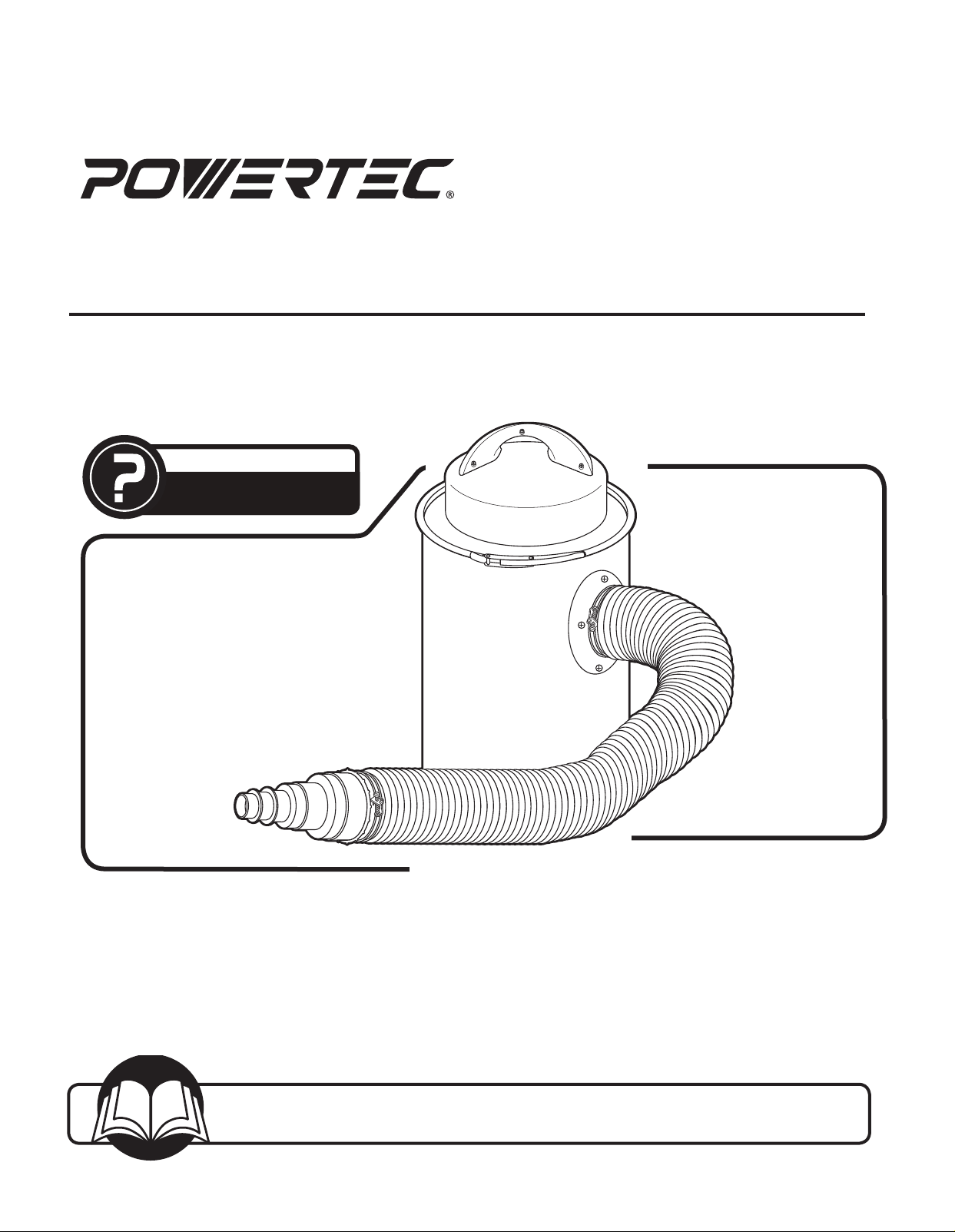
Owner’s Manual
Portable Dust Collector
QUESTION...
1•847•780•6120
Model No. DC1510
Visit us on the web at www.southerntechllc.com
You will need this manual for safety instructions, operating procedures, and warranty.
Put it and the original sales invoice in a safe, dry place for future reference.
17-0208
Page 2
TABLE OF CONTENTS
PRODUCT
SECTION PAGE
SAFETY RULES 1
Work Preparation
Work Area Preparation
Tool Maintenance
Tool Operation
ASSEMBLY 2
Unpacking
Installation
Power Source
Grounding Instructions
Extension Cords
Motor
Electrical Connections
OPERATION 5
Basic Operations
SPECIFICATIONS
Motor .............................................................. 120V/60Hz
Motor Power ..........................................1-1/2 HP 9.5 Amp
Filter ................................................................ 0.5 micron
Air Flow ............................................................... 108 CFM
Canister Capacity ................................... 13 gallons (50 L)
Hose Length ................................................. 78-3/4" (2 m)
Suction Connector Diameter ..........................4" (100 mm)
Gross Weight ............................................ 26.4 lbs (12 kg)
MAINTENANCE 5
General Maintenance
Cleaning
Lubrication
Machine Storage
Tool Repairs
PARTS ILLUSTRATION & 6
LIST
TROUBLESHOOTING 8
WARRANTY 9
Page 3

SAFETY RULES
WARNING
For your own safety, read and understand all warnings
and operating instructions before using any tool or
equipment.
WARNING
Some dust created by power sanding, sawing, grinding,
drilling and other construction activities contains chemicals known to the State of California to cause cancer, birth
defects or other reproductive harm.
Some examples of these chemicals are:
• Lead from lead-based paints.
• Crystalline silica from bricks and cement and
other masonry products.
• Arsenic and chromium from chemically-treated
lumber.
Your risk from these exposures vary, depending on how
often you do this type of work. To reduce your exposure to
these chemicals: work in a well ventilated area and work
with approved safety equipment. Always wear OSHA/
NIOSH approved, properly fitting face mask or respirator
when using such tools.
WARNING
Always follow proper operating procedures as defined in
this manual even if you are familiar with the use of this or
similar tools. Remember that being careless for even a
fraction of a second can result in severe personal injury.
WORK PREPARATION
• Wear proper apparel. Do not wear loose clothing, gloves,
neckties, rings, bracelets or other jewelry which may get
caught in moving parts of the tool.
• Wear protective hair covering to contain long hair.
• Wear safety shoes with non-slip soles.
• Wear safety glasses complying with United States ANSI
Z87.1. Everyday glasses have only impact resistant
lenses. They are NOT safety glasses.
• Wear face mask or dust mask if operation is dusty.
• Be alert and think clearly. Never operate power tools
when tired, intoxicated or when taking medications that
cause drowsiness.
WORK AREA PREPARATION
• Keep work area clean. Cluttered work areas
invite accidents.
• Do not use power tools in dangerous environments. Do
not use power tools in damp or wet locations. Do not
expose power tools to rain.
• Work area should be properly lit.
• Proper electrical receptacle should be available for
tool. Three-prong plug should be plugged directly into
properly grounded, three-prong receptacle.
• Extension cords should have a grounding prong and
the three wires of the extension cord should be of the
correct gauge.
• Keep visitors at a safe distance from work area.
1
• Keep children out of the work area. Ensure your work
shop is child-proof. Use padlocks, master switches or
remove switch keys to prevent any unintentional use of
power tools.
TOOL MAINTENANCE
• Always unplug tool prior to inspection.
• Consult manual for specific maintaining and
adjusting procedures.
• Keep tool lubricated and clean for a safe operation.
• Remove adjusting tools. Form habit of checking to
see adjusting tools or accessories are removed before
switching tool on.
• Keep all parts in working order. Check to determine that
guard or other parts will operate properly and perform
their intended function.
• Check for damaged parts. Check for alignment of
moving parts, binding, breakage, mounting and any
other condition that may affect tool’s operation.
• A guard or any other part that is damaged should
be properly repaired or replaced. Do not perform
makeshift repairs.
TOOL OPERATION
• Use the right tool for your job. Do not force your tool or
attachment to do a job for which it was not designed.
• Avoid accidental start-up. Make sure that the tool is in
the “OFF" position before plugging in.
• Never leave tool running unattended.
• Know your tool. Learn the tool’s operation, application
and specific limitations before using it.
CAUTION
Think safety! Safety is a combination of operator common
sense and alertness at all times when tool is being used.
WARNING
Do not attempt to operate tool until it is completely
assembled according to the instructions.
SAVE ALL WARNINGS AND INSTRUCTIONS
FOR FUTURE REFERENCE
SAFETY RULES
1
Page 4
2
SAFETY RULES
WARNING
Read and understand the instruction manual before
operating the dust collector. Basic precautions listed
below should always be followed when using your dust
collector to reduce the risk of injury, electrical shock
or fire.
• This dust collector is designed to collect sawdust only.
• Never attempt to use this dust collector to vacuum water
2
or any other liquids.
• Never try to use this dust collector to collect large
wood pieces.
• Never attempt to use this dust collector to collect
flammable or combustible dust/gas. DO NOT use near
any flammable or combustible liquids.
• Never attempt to use this dust collector to collect
anything that is burning or smoking.
• DO NOT use outdoors or on wet surfaces. Rain or
moisture entering the dust collector motor housing/
canister increases the risk of electrical shock.
SPECIFIC SAFETY INSTRUCTIONS
• Never attempt to use this dust collector to collect metal
materials such as screws, nails or other metal parts.
• Always wear approved eye protection and respirator
when emptying collection canister or changing filter
cartridge/bags.
• Turn machine off, disconnect power cord and ensure all
moving parts have stopped completely before changing
or emptying the collection canister.
• ALWAYS ensure filter cartridge/bags are secured
in place.
• Do not place your hand or tools near the open inlet
while operating. Serious personal injury or damage to
the machine can happen.
• Always connect dust collector to the matched
power source.
IMPORTANT : Always consider safety first as it applies
to your individual working conditions, the environment in
every shop is different.
SAVE ALL WARNINGS AND INSTRUCTIONS
FOR FUTURE REFERENCE
2
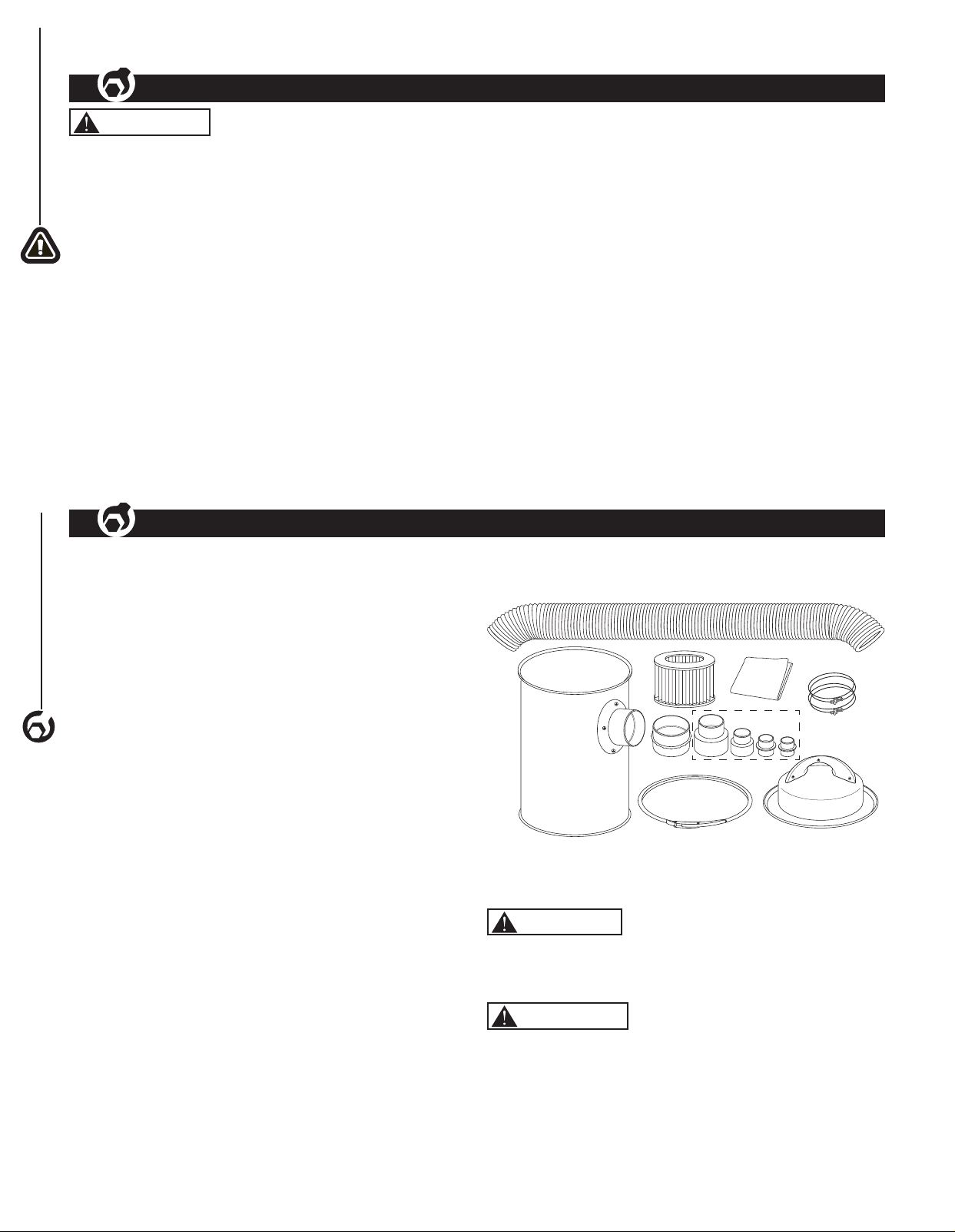
UNPACKING
ASSEMBLY
Refer to Figure 1.
• Check for shipping damage. Check immediately whether
all parts and accessories are included. If anything is
missing or broken, contact your retailer or call
847-780-6120.
• Carefully remove all contents from shipping carton.
NOTE: The loose parts are shipped inside the
collection canister.
The shipping carton contains:
2
ITEM DESCRIPTION QUANTITY
A Motor Housing
B Collection Canister 1
C Locking Band 1
D Collection Hose 1
E Hose Clamps 2
F Filter Cartridge 1
G Filter Bag 2
H Hose Coupler 1
I Stackable Hose Adapters 4
Owner's Manual (not shown)
ASSEMBLY
Figure 1
D
B
INSTALLATION
Refer to Figures 1 - 3
CAUTION
Do not attempt assembly if parts are missing.
Call the Customer service line to obtain replacement parts.
WARNING
• Do not operate dust collector until completely
assembled.
• Do not operate this tool until you have completely read
and understood this manual.
NOTE: After unit is assembled dispose of all packaging
material in an environmentally safe way.
E
F
H
C
G
A
I
A
Page 5

Tools required for assembly:
• Phillips head screwdriver
1. Slide the filter bag over the filter cartridge.
2. Fold and tuck the top of the bag into the
filter cartridge.
3. Push the filter cartridge/bag onto the motor housing.
Figure 2
Filter
Cartridge
Motor
Housing
Filter
Bag
4. Place the motor housing with filter cartridge/bag on
to the collection canister and lock in place with the
locking band.
5. Attach one end of the hose to the collection canister
inlet. Secure in place with supplied hose clamp. Make
sure the hose is flush with the collection canister hose
coupler before tightening the hose clamp.
6. Attach the supplied hose coupler to the other end of
the hose, secure in place with supplied hose clamp.
Figure 3
GROUNDING INSTRUCTIONS
WARNING
Improper connection of equipment grounding conductor
can result in the risk of electrical shock. Equipment
should be grounded while in use to protect operator from
electrical shock.
• Check with a qualified electrician if you do not
understand grounding instructions or if you are in doubt
as to whether the tool is properly grounded.
• This tool is equipped with an approved cord rated at
120V and a 3-prong grounding type plug (see Figure 4)
for your protection against shock hazards.
• Grounding plug should be plugged directly into a
properly installed and grounded 3-prong grounding type
receptacle, as shown (see Figure 4).
Figure 4
Properly Grounded Outlet
3-Prong Plug
Grounding Prong
ASSEMBLY
3
Motor
Housing
Locking
Band
Collection
Canister
Hose
Clamp
Hose
Coupler
Collection
Canister
Inlet
Hose
Clamp
Hose
POWER SOURCE
WARNING
Do not connect dust collector to the power source until all
assembly steps have been completed.
The motor is designed for operation on the voltage and
frequency specified. Normal loads will be handled safely
on voltages not more than 10% above or below specified
voltage. Running the unit on voltages which are not within
the range may cause overheating and motor burn-out.
Heavy loads require that the voltage at motor terminals be
no less than the voltage specified on nameplate.
• Do not remove or alter grounding prong in any manner.
In the event of a malfunction or breakdown, grounding
provides a path of least resistance for electrical shock.
WARNING
Do not allow fingers to touch the terminals of plug when
installing or removing from outlet.
• Plug must be plugged into matching outlet that is
properly installed and grounded in accordance with
all local codes and ordinances. Do not modify plug
provided. If it will not fit in outlet, have proper outlet
installed by a qualified electrician.
• Inspect tool cords periodically, and if damaged, have
repaired by an authorized service facility.
• Green (or green and yellow) conductor in cord is the
grounding wire. If repair or replacement of the electric
cord or plug is necessary, do not connect the green (or
green and yellow) wire to a live terminal.
EXTENSION CORDS
• The use of an extension cord is not recommended.
The use of any extension cord will cause some drop in
voltage and loss of power.
• Wires of the extension cord must be of sufficient size to
carry the current and maintain adequate voltage.
• Use the table to determine the minimum wire size
(A.W.G.) extension cord.
• Use only 3-wire extension cords having 3-prong
grounding type plugs and 3-pole receptacles which
accept the tool plug.
• If the extension cord is worn, cut or damaged in any
way, replace it immediately.
Page 6

Extension Cord Length
ASSEMBLY
Wire Size…………….. 18 A.W.G.
Up to 50 ft
NOTE: Using extension cords over 50 ft. long is not
recommended.
MOTOR
The dust collector is assembled with motor and wiring
installed. The electrical wiring schematic is shown in
Figure 5.
4
The permanently split capacitor motor has the following
specifications:
Horsepower (Peak HP) ............................................ 1-1/2
Voltage ...................................................................... 120
Amp ............................................................................ 9.5
Hertz ............................................................................ 60
Phase .................................................................... Single
RPM ......................................................................... 3100
ELECTRICAL CONNECTIONS
Figure 5
WARNING
All electrical connections must be performed by a qualified
electrician. Make sure tool is off and disconnected
from power source while motor is mounted, connected,
reconnected or anytime wiring is inspected. Motor and
wires are installed as shown in wiring schematic (See
Figure 5). Motor is assembled with approved, 3-conductor
cord to be used at 120 volts.
The power lines are inserted directly into the switch. The
green ground line must remain securely fastened to the
frame to properly protect against electrical shock. The
power supply to the motor is controlled by a single pole
locking rocker switch.
Page 7

OPERATION
5
ASSEMBLY
OPERATION
BASIC OPERATIONS
Refer to Figures 6 - 7
Before Starting
• Place the dust collector near the dust producing
machine to be used.
• There are four hose adapters supplied. Select the hose
adapter that best fits the machine outlet and attach it to
the hose coupler.
Figure 6
Hose
Adapters
• Connect the dust collector adapter to the machine
outlet. Make sure the connection is secure.
• Make sure the machine is turned OFF.
• Connect the dust collector's power cord to the correct
power source.
To Start
• Place the dust collector's ON/OFF switch in the ON (I)
position.
• Turn the machine ON.
Figure 7
5
On/Off
Switch
To Stop
IMPORTANT: ALWAYS turn the dust producing machine
OFF before turning the dust collector OFF.
• Turn the machine OFF.
• Place the dust collector's ON/OFF switch in the OFF (O)
position.
MAINTENANCE
GENERAL MAINTENANCE
WARNING
Make sure the machine is turned off and the cord is
disconnected from the power source before servicing and
removing/replacing any components on the machine.
• Check the dust collector daily for loose connections,
damaged wires, worn switch, full collection canister,
dirty filter cartridge/bag and any other unsafe condition.
CLEANING
Check and empty the collection canister on your dust
collector regularly. The machine operates at a much
higher level of efficiency when the collection canister is
empty.
Check and clean the filter cartridge/bag regularly. Replace
as needed.
5
LUBRICATION
The sealed bearings in the motor have been permanently
lubricated at the factory. They require no further
lubrication.
MACHINE STORAGE
• When the dust collector is not in use, disconnect the
cord from the power source and store the machine in a
dry place.
• Do not expose the machine to rain.
• Ensure the cord is kept away from potential damage
sources such as; sharp objects, chemicals, heat
sources and water.
TOOL REPAIRS
• If power cord is worn, cut, or damaged in any way, have
it replaced immediately.
• Replace any damaged or missing parts. Use parts list
to order parts. Any attempt to repair motor may create
a hazard unless repair is done by a qualified service
technician. Call the customer service line at
847-780-6120 for assistance.
MAINTENANCE
5
Page 8

6
PARTS LIST
6
PORTABLE DUST COLLECTOR PARTS ILLUSTRATION
Page 9

PORTABLE DUST COLLECTOR PARTS LIST
Key No. Part No Description Qty
1 DC1510001 Power cord 1
2 DC1510002 Cord bush 1
3 DC1510003 Switch Gorbo XCK-019 1
4 DC1510004 Left guard 1
5 DC1510005 Lock nut M5 3
6 DC1510006 Philips screw M5X25 1
7 DC1510007 Philips screw M5X45 2
8 DC1510008 Right guard 1
9 DC1510009 Circle sponge 1
10 DC1510010 Long sponge 3
11 DC1510011 Rubber washer 2
12 DC1510012 Philips screw M5X8 4
13 DC1510013 Motor 120V 1
14 DC1510014 Rubber washer 1
15 DC1510015 Filter 1
16 DC1510016 Dust bag 2
17 DC1510017 Drum lid 1
18 DC1510018 Philips screw ST5.5X18 3
19 DC1510019 Seal gasket 2
20 DC1510020 Drum clamp 1
21 DC1510021 Drum 1
22 DC1510022 Lock nut M6 4
23 DC1510023 Flat washer Φ6 8
24 DC1510024 Suction inlet 1
25 DC1510025 Philips screw M6X15 4
26 DC1510026 Iron wire clamp 4” 2
27 DC1510027 PipeΦ100X2000mm 1
28 DC1510028 Pipe connector 1
29 DC1510029 Suction inlet Assy 1
7
PARTS LIST
7
Page 10

8
SYMPTOM POSSIBLE CAUSE(S) CORRECTIVE ACTION
TROUBLESHOOTING
Motor will not start 1. Low voltage
2. Open circuit in motor or loose
connections
3. Defective switch
TROUBLESHOOTING
1. Check power line for proper voltage
2. Inspect all lead connections on motor for loose or
open connection
3. Replace switch
8
Motor will not start;
fuses blown or circuit
breakers are tripped
Unit has vibration or
noisy operation
Loud, repetitious
noise or excessive
vibration coming from
dust collector
Sawdust blown into
the air from the dust
collector
1. Short circuit in line cord or plug
2. Short circuit in motor or loose
connections
3. Incorrect fuses or circuit breakers in
power line
1. Motor or components are loose
2. Motor bearings faulty
1. Dust collection canister is full
2. Filter cartridge/bag is dirty or
damaged
3. Dust collector hose restricted
4. The lumber is wet and dust is not
flowing through the hose smoothly
5. There is a leak in the hose
Hose clamps or dust collection canister
is not properly clamped and secured.
1. Inspect line cord or plug for damaged insulation
and shorted wires
2. Inspect all lead connections on motor for loose or
shorted terminals or worn insulation on wires
3. Install correct fuses or circuit breakers
1. Inspect/replace any stripped or damaged bolts/
nuts and retighten.
2. Call the customer service line at 847-780-6120
for assistance
1. Empty collection canister.
2. Clean filter cartridge/bag or replace.
3. Remove hose from dust collector inlet and
unblock the restriction in the hose. A plumbing
snake may be necessary.
4. Process lumber with less than 20% moisture
content.
5. Inspect and replace hose.
Make sure hose clamps are tight and completely
over the hose. Make sure motor housing is seated
on collection canister correctly and locked in place
with the locking band.
Page 11

WARRANTY
Thank you for investing in a POWERTEC power tool. This product has been designed and manufactured to meet high
quality standards and is guaranteed for domestic use against defects in workmanship or material for a period of 12
months from the date of purchase. This guarantee does not affect your statutory rights.
SOUTHERN TECHNOLOGIES. BENCH TOP AND STATIONARY POWER TOOL
LIMITED 1 YEAR WARRANTY AND 30-DAY SATISFACTION GUARANTEE POLICY
POWERTEC products are designed and manufactured by Southern Technologies LLC. All warranty communications
should be directed to Southern Technologies LLC by calling 847-780-6120 (toll free), 9 AM to 5 PM, Monday through
Friday, US Central Time.
30- DAY SATISFACTION GUARANTEE POLICY
During the first 30 days after the date of purchase, if you are dissatisfied with the performance of this POWERTEC tool
for any reason, you may return the tool to the retailer from which it was purchased for a full refund or exchange. You
must present proof of purchase and return all original equipment packaged with the original product. The replacement
tool will be covered by the limited warranty for the balance of the one year warranty period.
LIMITED ONE YEAR WARRANTY
This warranty covers all defects in workmanship or materials in this POWERTEC tool for a one year period from the
date of purchase. This warranty is specific to this tool. Southern Technologies, LLC reserves the right to repair or
replace the defective tool, at its discretion.
9
WARRANTY
9
HOW TO OBTAIN SERVICE
To obtain service for this POWERTEC tool you must return it, freight prepaid, to POWERTEC. You may call (toll
free) 847-780-6120 for more information. When requesting warranty service, you must present the proof of purchase
documentation, which includes a date of purchase. POWERTEC will either repair or replace any defective part, at
our option at no charge to you. The repaired or replacement unit will be covered by the same limited warranty for the
balance of one year warranty period.
WHAT IS NOT COVERED
This warranty applies to the original purchaser at retailer and may not be transferred.
This warranty does not cover consumable items such as saw blades, knives, belts, discs, cooling blocks and sleeves.
This warranty does not cover required service and part replacement resulting from normal wear and tear, including
accessory wear.
This warranty does not cover any malfunction, failure or defect resulting from:
1) misuse, abuse, neglect and mishandling not in accordance with the owner’s manual.
2) damage due to accidents, natural disasters, power outage, or power overload.
3) commercial or rental use.
4) alteration, modification or repair performed by persons not recommended by POWERTEC.
DISCLAIMER
To the extent permitted by applicable law, all implied warranties, including warranties of MERCHANTABILITY or
FITNESS FOR A PARTICULAR PURPOSE, are disclaimed. Any implied warranties, that cannot be disclaimed under
state law are limited to one year from the date of purchase. Southern Technologies LLC. is not responsible for direct,
indirect, incidental or consequential damages. Some states do not allow limitations on how long an implied warranty
lasts and/or do not allow the exclusion or limitation of incidental or consequential damages, so the above limitations
may not apply to you. This warranty gives you specific legal rights, and you may also have other rights which vary from
state to state. Southern Technologies LLC., makes no warranties, representations, or promises as to the quality or
performance of its power tools other than those specifically stated in this warranty.
Page 12

Southern Technologies, LLC
3816 Hawthorn CT,
Waukegan, IL 60087
 Loading...