

PowerTec BJ600, Pro BJ600 Owner's Manual
Owner’s Manual
QUESTION...
1•877•393•7121
6” BENCH JOINTER
WITH BUILT-IN DUST COLLECTION
Model No. BJ600
Visit us on the web at www.southerntechllc.com
You will need this manual for safety instructions, operating procedures, and warranty.
Put it and the original sales invoice in a safe, dry place for future reference.
09-0909

TABLE OF CONTENTS
SECTION PAGE
SAFETY RULES 1
Work Preparation
Work Area Preparation
Tool Maintenance
Tool Operation
ASSEMBLY 2
PARTS ILLUSTRATION & 13
LIST
WARRANTY 15
PRODUCTION
SPECIFICATIONS
Unpackaging
Attach Fence Support
Install Fence
Attach Dust Collection Bag
Mount Jointer
Power Source
Grounding Instructions
Extension Cords
Motor
Electrical Connections
OPERATION 6
Description
Specifications
Safety Precautions
Position Fence
Check Blade Outfeed Table Alignment
Adjust the Height of the Cutterhead Blades
Adjust the Depth of Cut
Measure the Depth of Cut
Check the Blade Guard
On-Off Switch
Feed Direction
Feed the Workpiece
Use Hold Down/Push Blocks
Bevel and Chamfer
Voltage...........................................................................120
Amps................................................................................12
Hertz................................................................................60
Phase.........................................................................Single
Cutter Head Speed..........................................10,000 RPM
Table Size.......................28-1/2 x 6-1/4 in (72.4 x 15.9 cm)
Blade Width................................................6-1/8” (15.6 cm)
Maximum Depth of Cut.....................................1/8” (3 mm)
Cuts per Minute.........................................................20,000
Dust Collection Port.....................................2-1/2” (62 mm)
MAINTENANCE 10
Replace the Blades
Sharpening the Blades
Replace the Fan Belt
Replace the Drive Belt
Inspect and Replace Motor Brushes
General Maintenance and Lubrication
Keep Tool in Repair
TROUBLESHOOTING 12

SAFETY RULES
1
WARNING
For your own safety, read and understand all warnings
and operating instructions before using any tool or
equipment.
WARNING
Some dust created by operation of power tool contains
chemicals known to the State of California to cause
cancer, birth defects or other reproductive harm.
To reduce your exposure to these chemicals: work in a
well ventilated area and work with approved safety
equipment. Always wear OSHA/NIOSH approved,
properly fitting face mask or respirator when using such
tools.
WARNING
Failure to follow these rules may result in serious personal
injury. Remember that being careless for even a fraction
of a second can result in severe personal injury.
WORK PREPARATION
• Wear proper apparel. Do not wear loose clothing,
gloves, neckties, rings, bracelets or other jewelry which
may get caught in moving parts of the tool.
• Nonslip protective footwear is recommended. Wear
protective hair covering to contain long hair.
• Wear eye and hearing protection. Always use safety
glasses. Eye protection equipment should comply with
ANSI Z87.1 standards. Hearing equipment should
comply with ANSI S3.19 standards.
• Wear face mask or dust mask if operation is dusty.
• Be alert and think clearly. Never operate power tools
when tired, intoxicated or when taking medications that
cause drowsiness.
WORK AREA PREPARATION
• Keep work area clean. Cluttered work areas and
benches invite accidents.
• Work area should be properly lighted.
• Do not use the machine in a dangerous environment.
The use of power tools in damp or wet locations or in
rain can cause shock or electrocution.
• Three-prong plug should be plugged directly into
properly grounded, three-prong receptacle.
• Use the proper extension cord. Make sure your
extension cord is in good condition and should have a
grounding prong and the three wires of
extension cord should be of the correct gauge.
• Keep children and visitors away. Your shop is a poten tially dangerous environment. Children and visitors can
be injured.
• Make your workshop childproof with padlocks, master
switches or remove switch keys to prevent any uninten tional use of power tools.
(new bulklet)
TOOL MAINTENANCE
• Turn the machine "OFF", and disconnect the machine
from the power source prior to inspection.
• Maintain all tools and machines in peak condition. Keep
tools sharp and clean for best and safest performance.
• Follow instructions for lubricating and changing
accessories.
• Check for damaged parts. Check for alignment of
moving parts, binding, breakage, mounting and any
other condition that may affect tool's operation.
• Poorly maintained tools and machines can further
damage the tool or machine and/or cause injury.
• A guard or any other part that is damaged should be
repaired or replaced. Do not perform makeshift repairs.
TOOL OPERATION
• Avoid accidental start-up. Make sure that the tool is in
the “OFF” position before plugging in.
• Use the right tool for your job. Do not force your
tool or attachment to do a job for which it was not
designed.
• Disconnect tool when changing parts.
• Don't force the workpiece on the machine. Damage to
the machine and/or injury may result.
• Never leave tool running unattended. Turn the power off
and do not leave tool until it comes to a complete stop.
• Do not overreach. Loss of balance can make you fall
into a working machine, causing injury.
• Never stand on tool. Injury could occur if the tool tips, or
if you accidentally contact the cutting tool.
• Know your tool. Learn the tool’s operation, application
and specific limitations before using it.
• Use recommended accessories. Use of improper
accessories may cause damage to the machine or injury
to the user.
• Handle workpiece correctly. Keep hands away from
moving parts.
• Turn tool off if it jams. .
CAUTION: Think safety! Safety is a combination of operator common sense and alertness at all times when tool is
being used.
(remove extra period)
WARNING
Do not attempt to operate tool until it is completely
assembled according to the instructions.
2
I
H
L
J
K
G
F
E
D
A
B
C
ASSEMBLY
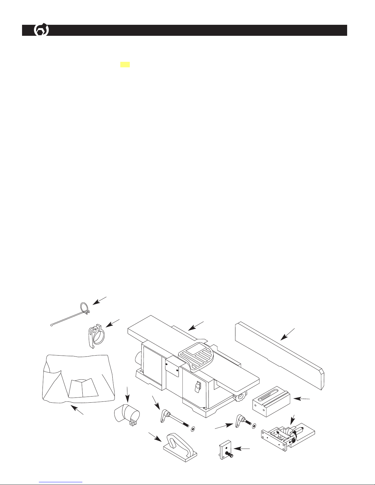
UNPACKAGING
Refer to Figure 1.
The machine is shipped complete in on container.
Carefully unpack the machine and all loose items from the
shipping container. Fig 1 illustrates the machine and all
loose items.
Check for shipping damage. A claim must be filled with
carrier if damage has occurred.
A Jointer bed assembly
B Fence
C Fence support
D Fence bracket assembly
E Locking plate assembly
F Fence sliding handle with spacer
G Push blocks (2)
H Fence tilting handle with spacer
I Dust chute
J Dust Collection Bag
K Dust Collection Clamp
L Dust Collection Wire
one
Hardware bag includes:
8-1, 25 x 25 mm socket head bolts (6)
8mm lock washer (6)
4 and 6mm hex wrench
6-1.0 x 25mm pan head screw
Figure 1 - Unpacking
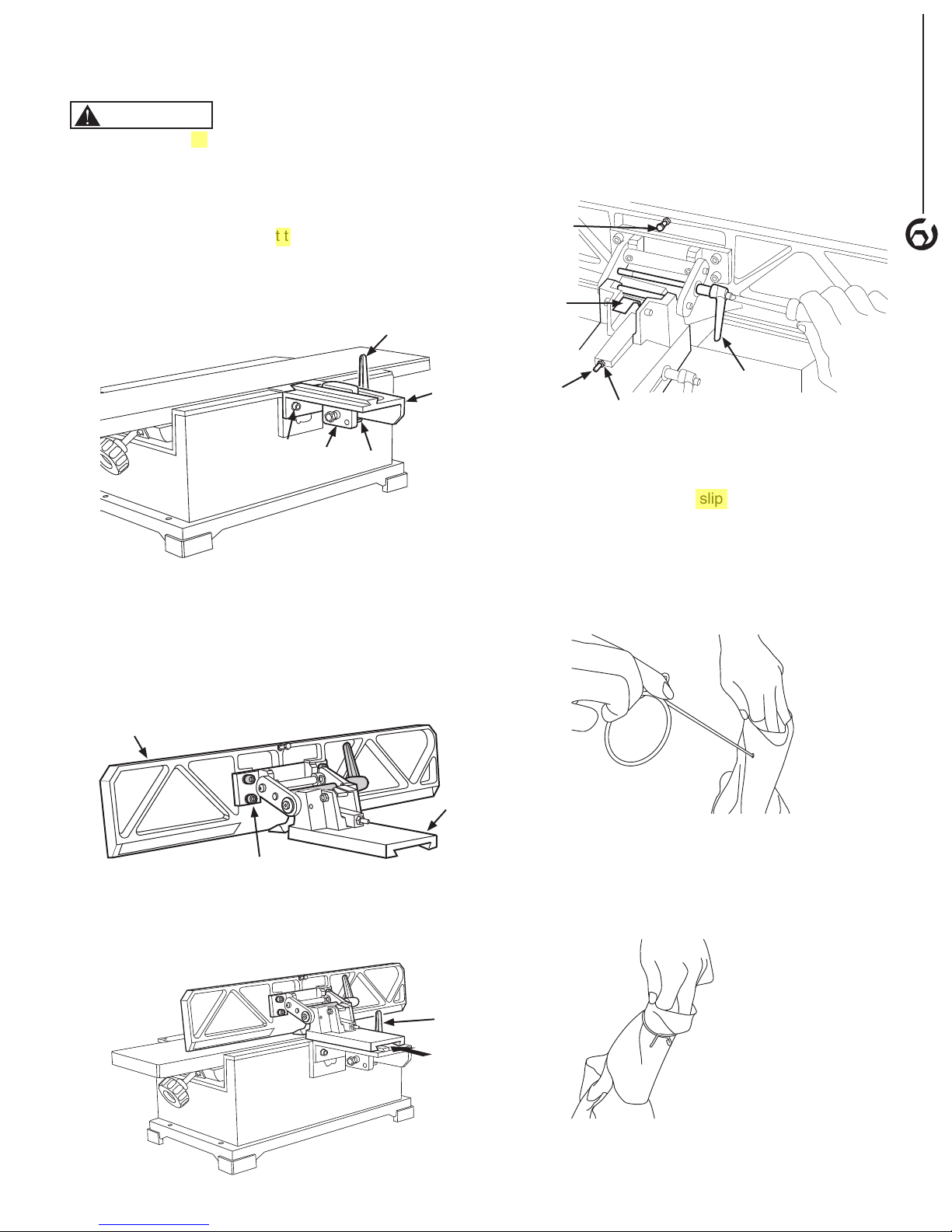
ATTACH FENCE SUPPORT
Figure 2-1
WARNING
Turn the switch to OFF position and disconnect the
machine from power source.
• Use two socket head bolts and washers to lock the
fence support to the jointer.
• Insert locking plate assembly (E) into fence support (C).
Position locking plate so that two pins are against the
bottom edge of the fence support.
• Secure the locking plate in position with fence sliding
handle (F) and spacer.
Figure 2-1 - Attach Fence Support
the
the
F
• Slide fence forward so that the fence contacts the
cutterhead guard. At this position the cutterhead is
completely covered by cutterhead guard.
• Install fence tilting handle (H) with spacer through right
link and thread into left link. (Figure 3)
Figure 3 - Attach Fence Assembly
Outward Stop
Limit Plate
ASSEMBLY
3
C
Socket
Head Bolt
E
Pin
INSTALL FENCE
Figure 2-2 and 2-3
• Use the four socket head bolts and washers to attach
fence (B) to Fence bracket assembly (D).
Figure 2-2 - Assembling Fence and Fence Bracket
B
Shaft
Hex Nut
H
ATTACH DUST COLLECTION BAG
Refer to Figure 1 and 4
• Install the Dust Chute (I) by slip it over the Dust Port.
Tighten the screw on the Dust Chute (I).
• Insert Dust Bag Wire (L) through a small hole on the
sleeve of Dust Bag (J).
Figure 4 - 1
D
slipping
Socket Head Bolt
• Slide fence and bracket (B+D) over and onto dovetails
of support and locking plate (C+E). (Figure 2-3)
Figure 2-3 - Assembling Fence and Fence Bracket
• Draw the open end of Dust Bag (J) sleeve through the
ring of Dust Bag Wire (L).
Figure 4 - 2
F
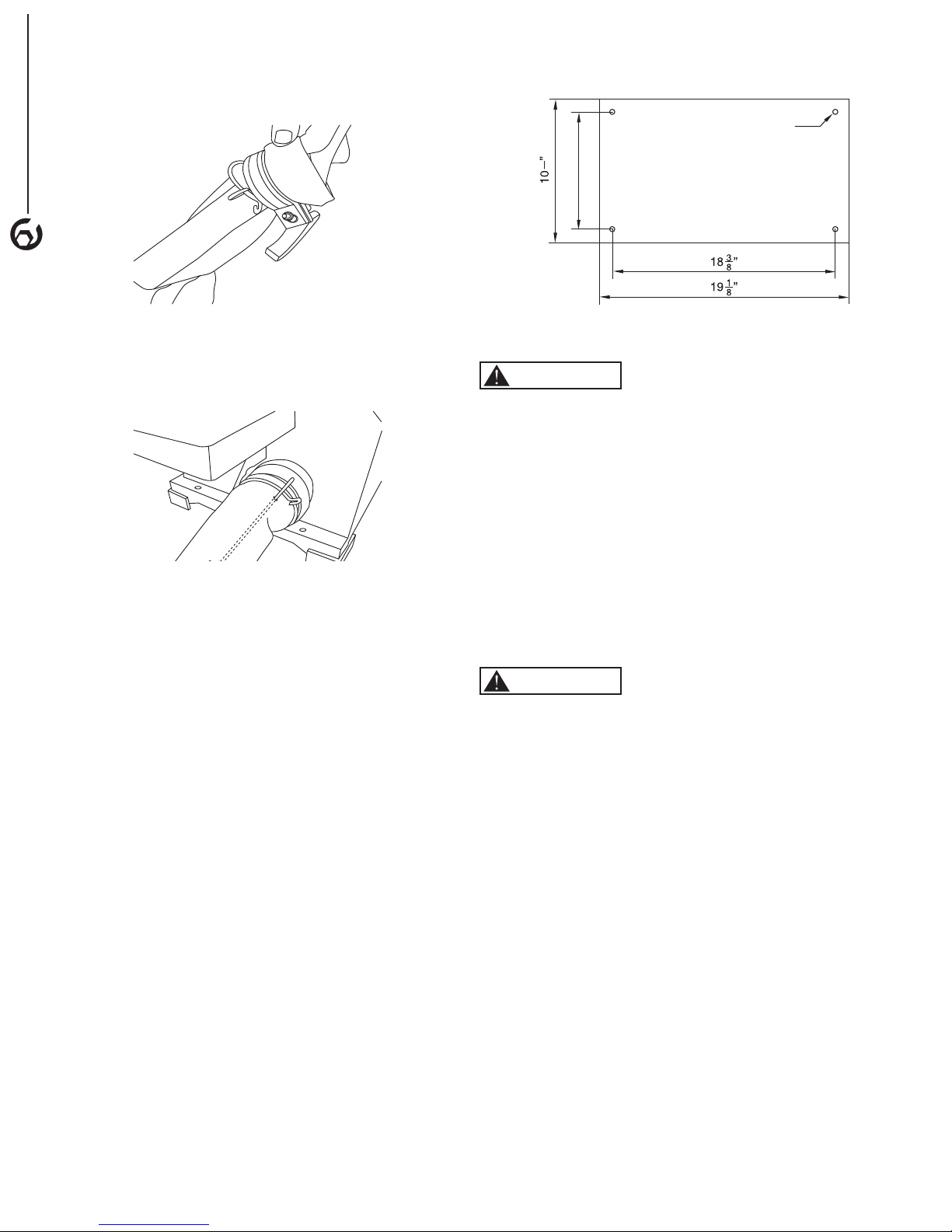
• Place Clamp (K) over Dust Bag (J) Sleeve.
1
4
ASSEMBLY
Figure 4 - 3
4
• Slide Sleeve with Clamp (K) and Dust Bag Wire (L) Ring
over Dust Chute (I).
Figure 5 - Jointer/Planer Foot Print
3/8”
6-5/16”
POWER SOURCE
Figure 4 - 4
• Secure Dust Bag (J) in position. Rotate the handle on
the Clamp (K) to adjust the clamp size so it can slide
over the Dust Chute (I). Press the handle to tighten the
Clamp (K).
• The Dust Bag (J) should be secured on the Dust Chute
(I) now.
MOUNT JOINTER
• The machine must be installed in a well-lighted area
with correct power supply.
• The machine can be installed on either a workbench or
a tool stand by using bolts, lock washers, and hex nuts.
• The machine must be bolted to a firm and level surface.
• There must be enough clearance for the moving
workpiece during operation. There must be enough
room for safety operation of the machine.
• Figure 5 shows the base dimensions and mounting
holes.
WARNING
Do not connect to the power source until the machine is
completely assembled.
The machine is wired for 120 volts, 60 HZ alternating
current. Before connecting the machine to the power
source, make sure the switch is in the "OFF" position.
Running the unit on voltages which are not within range
may cause overheating and motor burn-out. Heavy loads
require that voltage at motor terminals be no less than the
voltage specified on nameplate.
• Power supply to the motor is controlled by a locking
rocker switch. Remove the key to prevent unauthorized
use.
GROUNDING INSTRUCTIONS
WARNING
Improper connection of equipment grounding conductor
can result in the risk of electrical shock.
• The machine should be grounded while in use to protect
operator from electrical shock.
• In the event of an electrical short circuit, grounding
reduces the risk of electrical shock by providing an
escape wire for the electric current.
• This machine is equipped with an approved
3-conductor cord rated at 150V and a 3-prong
grounding type plug (Figure 6) for your protection
against shock hazards.
• Grounding plug should be plugged directly into a
properly installed and grounded 3-prong grounding-type
receptacle, as shown (Figure 6)
• The plug must be plugged into an outlet that is properly
installed and grounded in accordance with all local
codes and ordinances.
• Check with a qualified electrician or service personnel if
these instructions are not completely understood or if in
doubt as to whether the tool is properly grounded.
• Do not modify plug provided. If it will not fit in outlet,
have proper outlet installed by a qualified electrician.
Use only 3-wire extension cords, that have 3-prong
grounding type plugs and matching 3-conductor
receptacles that accept the machine's plug, as show in
Figure 6
 Loading...