

Page 1
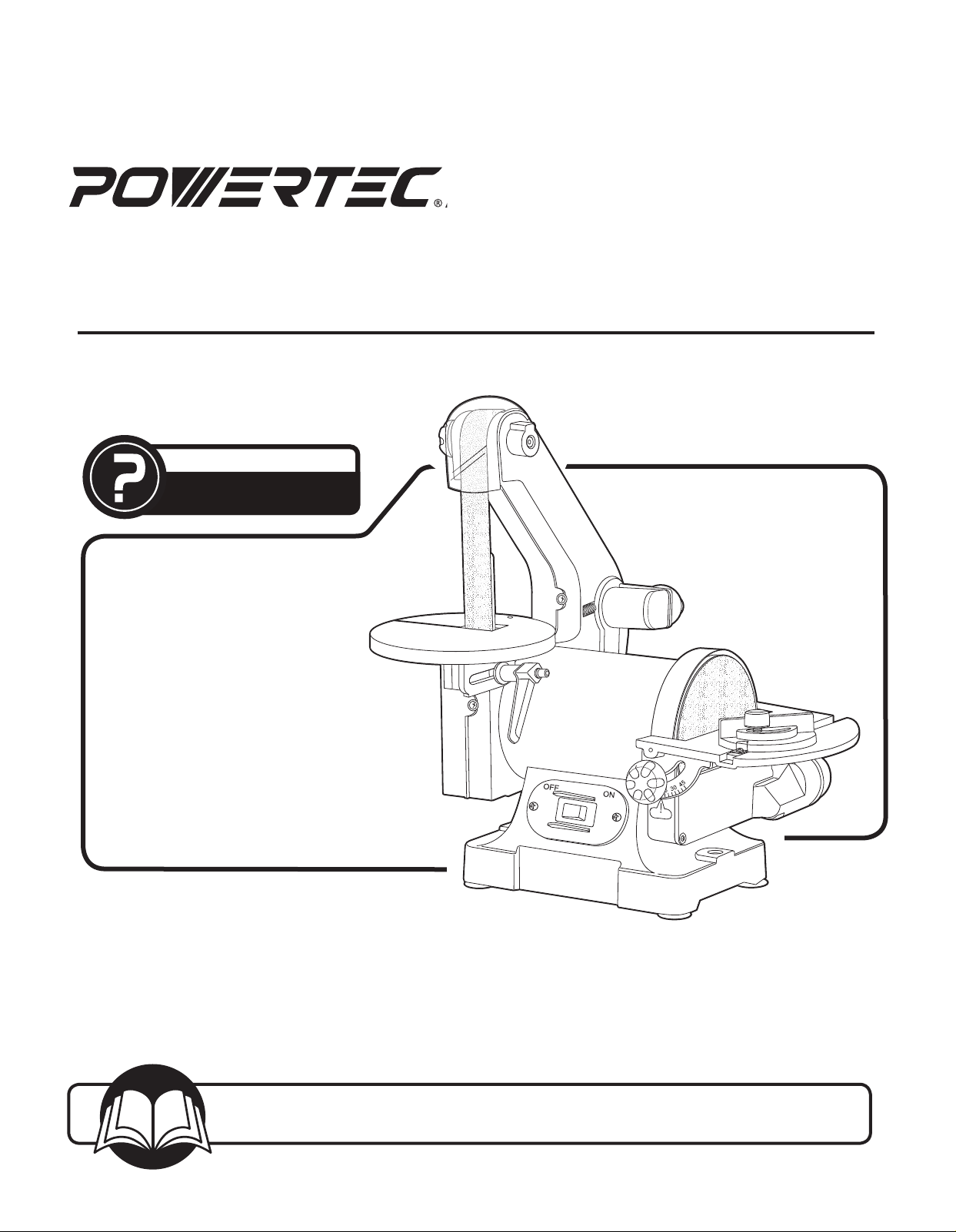
Model No. BD1502
Owner’s Manual
1" X 30" BELT and 5" DISC SANDER
QUESTION...
1•847•780•6120
Visit us on the web at www.southerntechllc.com
You will need this manual for safety instructions, operating procedures, and warranty.
Put it and the original sales invoice in a safe, dry place for future reference.
17-0303
Page 2
TABLE OF CONTENTS PRODUCT SPECIFICATIONS
SECTION PAGE
SAFETY RULES 1
Work Preparation
Work Area Preparation
Tool Maintenance
Tool Preparation
ASSEMBLY 2
Unpacking
Tools Needed
Assemble the Dust Chute
Assemble the Sanding Disc Table
Assemble the Sanding Belt Table
Replacing the Sanding Belt
Sanding Belt Tracking Adjustment
Backstop
Replacing the Sanding Disc
Dust Port Options
Mounting the Sander to Work Surface
Power Source
Grounding Instructions
Motor
Extension Cords
Electrical Connections
Horsepower .................................1/3
Voltage .................................... 120
Amp .......................................2.3
Hertz ....................................... 60
Phase ................................... Single
RPM ..................................... 3450
Belt Size ................................ 1" x 30"
Belt Table Dimension ........................5-3/4"
Disc Diameter .................................5"
Disc Table Dimensions ...................4" x 7-1/4"
Dust Ports Diameter
Side Belt Guard ...................... 1-3/4" OD
Sanding Disc Dust Chute .............. 1-3/4" OD
Base Dimensions .....................8-1/2"x 11-1/2"
Net Weight ..................................16 lb
OPERATION 8
ON/OFF Switch
Surface Sanding On Sanding Belt
End Sanding - Disc/Belt
Miter Gauge - Disc Sander
Contour Sanding With The Belt
MAINTENANCE 9
General Maintenance
Lubrication
PARTS ILLUSTRATION & 10
LIST
TROUBLESHOOTING 12
WARRANTY 13
Page 3

GENERAL SAFETY RULES
WARNING
For your own safety, read and understand all warnings and
operating instructions before using any tool or equipment.
WARNING
The 1" belt sander can be used for processing wood and
metal products. However, combining both wood dust and
metal filings can create a FIRE HAZARD. Make certain dust
collector is free of wood dust deposits before processing
metal products.
WARNING
Some dust created by power sanding, sawing, grinding,
drilling and other construction activities contain chemicals
known to the State of California to cause cancer, birth defects
or other reproductive harm.
Some examples of these chemicals are:
• Lead from lead-based paints.
• Crystalline silica from bricks and cement and other
masonry products.
• Arsenic and chromium from chemically-treatedlumber.
Your risk from these exposures vary, depending on how
often you do this type of work. To reduce your exposure to
these chemicals: work in a well ventilated area and work
with approved safety equipment. Always wear OSHA/NIOSH
approved, properly fitting face mask or respirator when using
such tools.
WARNING
Failure to follow these rules may result in serious personal
injury. Remember that being careless for even a fraction of a
second can result in severe personal injury.
WORK PREPARATION
• Wear proper apparel. Do not wear loose clothing, gloves,
neckties, rings, bracelets or other jewelry which may get
caught in moving parts of the tool.
• Nonslip protective footwear is recommended. Wear
protective hair covering to contain long hair.
• Wear eye and hearing protection. Always use safety
glasses. Eye protection equipment should comply with
ANSI Z87.1 standards. Hearing equipment should comply
with ANSI S3.19 standards.
• Wear face mask or dust mask if operation is dusty.
• Be alert and think clearly. Never operate power tools when
tired, intoxicated or when taking medications that cause
drowsiness.
WORK AREA PREPARATION
• Keep work area clean. Cluttered work areas and benches
invite accidents.
• Work area should be properly lighted.
• Do not use the machine in a dangerous environment. The
use of power tools in damp or wet locations or in rain can
cause shock or electrocution.
• Three-prong plug should be plugged directly into properly
grounded, three-prong receptacle.
• Use the proper extension cord. Make sure your extension
cord is in good condition. It should have grounding prong
and should be of the correct gauge.
1
• Keep children and visitors away. Your shop is a potentially
dangerous environment. Children and visitors can be
injured.
• Make your workshop childproof with padlocks, master
switches or remove switch keys to prevent any
unintentional use of power tools.
• It should have a grounding prong and should be of the
correct gauge.
TOOL MAINTENANCE
• Turn the machine "OFF", and disconnect the machine from
the power source prior to inspection.
• Maintain all tools and machines in peak condition. Keep
tools sharp and clean for best and safest performance.
• Follow instructions for lubricating and changing
accessories.
• Check for damaged parts. Check for alignment of moving
parts, binding, breakage, mounting and any other condition
that may affect tool's operation.
• Poorly maintained tools and machines can further damage
the tool or machine and/or cause injury.
• A guard or any other part that is damaged should be
repaired or replaced. Do not perform makeshift repairs.
TOOL OPERATION
• Avoid accidental start-up. Make sure that the tool is in the
“OFF” position before plugging in.
• Use the right tool for your job. Do not force your tool or
attachment to do a job for which it was not designed.
• Disconnect tool when changing parts. Always use
manufacturer recommended belts and disc.
• Don't force the workpiece on the machine. Damage to the
machine and/or injury may result.
• Never leave tool running unattended. Turn the power off
and do not leave tool until it comes to a complete stop.
• Do not overreach. Loss of balance can make you fall into a
working machine, causing injury.
• Never stand on tool. Injury could occur if the tool tips, or if
you accidentally contact the cutting tool.
• Know your tool. Learn the tool’s operation, application and
specific limitations before using it.
• Use a proper extension cord of the correct gauge. Your
extension cord should have a grounding prong, and should
be in good condition.
• Handle workpiece correctly. Keep hands away from
moving parts.
• Turn tool off if it jams.
• Always support the workpiece against the table or backstop
when sanding.
• Always feed workpiece against the direction of the sanding
rotation. To maintain control, properly support long or wide
work-pieces.
CAUTION
Think safety! Safety is a combination of operator common
sense and alertness at all times when tool is being used.
WARNING
Do not attempt to operate tool until it is completely
assembled according to the instructions.
SAVE ALL WARNINGS AND INSTRUCTIONS
FOR FUTURE REFERENCE
SAFETY RULES
1
Page 4
ASSEMBLY
2
ASSEMBLY
UNPACKING
Refer to Figure 1.
Check for shipping damage. Check immediately whether
all parts and accessories are included.
The sander comes assembled as one unit. Additional
parts which need to be fastened to sander, should be
located and accounted for before assembling.
2
ITEM DESCRIPTION QUANTITY
A Dust Chute (with dust nozzle adapter) 1
B Screw M4×10 (dust chute assembly) 3
C Spring washer (dust chute assembly) 3
D Sanding Disc Table 1
E Locking Knobs (sanding disc table) 2
F Washers (sanding disc table) 2
G Sanding Belt Table 1
H Locking Lever (Sanding Belt Table) 1
I Washer 8 mm (Sanding Belt Table) 1
J Miter Gauge 1
K Hex Wrench 1
L Operators Manual (not shown) 1
Figure 1
D
J
20
30
10
40
0
10
20
30
40
G
A
B
C
K
E
I
H
WARNING
Do not use the machine until it is completely assembled
and you have read and understood the entire
operating manual.
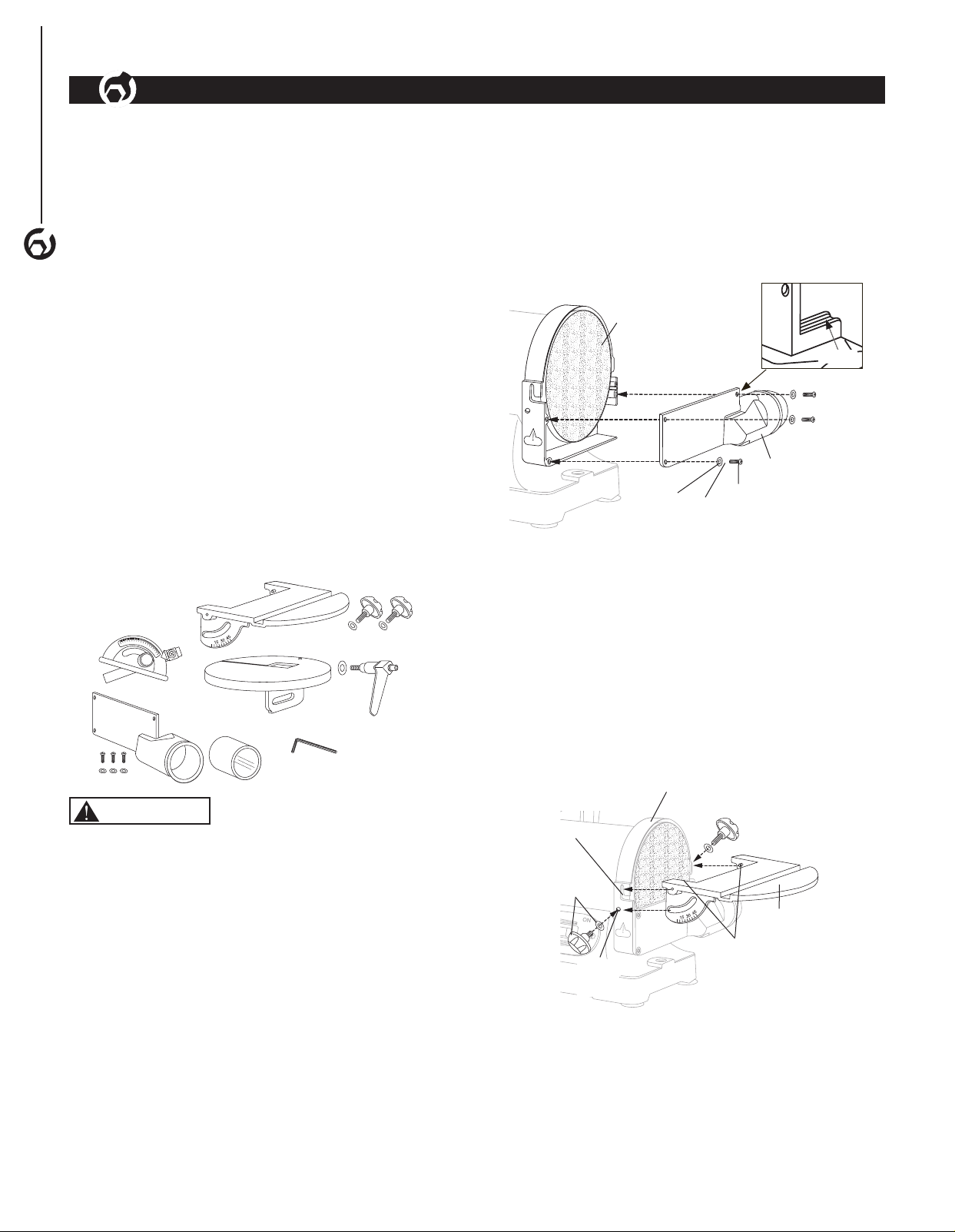
ASSEMBLE THE DUST CHUTE
Refer to Figure 2
• Slide the groove in the dust chute onto the sanding disc
guard casting as shown. Secure the dust chute to the
sander with screws, flat washers and spring washers
supplied. Ensure the dust chute opening faces the rear
of the unit.
Figure 2
Sanding Disc
Groove
Dust Chute
Flat
Washers
Washers
Screws
ASSEMBLE THE SANDING DISC TABLE
Refer to Figure 3, 4
F
• Align the sanding disc table to the sanding disc guard
• Align the pins on the sanding disc table with slots on
the sanding disc guard. Slide the pins in and up into
the slot.
• Place a washer on each locking knob.
• While holding the sanding disc table in place, thread
a locking knob into the slot on each side of the table.
Tighten each locking knob.
Figure 3
Sanding Disc
Guard
Slot
Locking
Knob and
Washer
TOOLS NEEDED
The following tools (not included) are needed to assemble
and adjust the belt/disc sander:
• Combination square
• Phillips screwdriver
• Standard screwdriver
• 4 mm Hex Wrench
Hole for
Locking
Knob
Pins
Sanding
Disc
Table
Page 5
To adjust sanding disc table
• Place a square on the table with the ruler side against
the sanding disc. The table should be 90° to the
sanding disc.
• If the table is not 90° to the sanding disc, loosen the
locking knobs and tilt table up and down until it is 90°
to the sanding disc. Tighten locking knobs securely.
Recheck adjustment using the square.
• For bevel sanding, loosen the locking knobs and tilt
table up and down between 0 –45° to desired angle.
Figure 4
Sanding
Locking
Knob
Disc Table
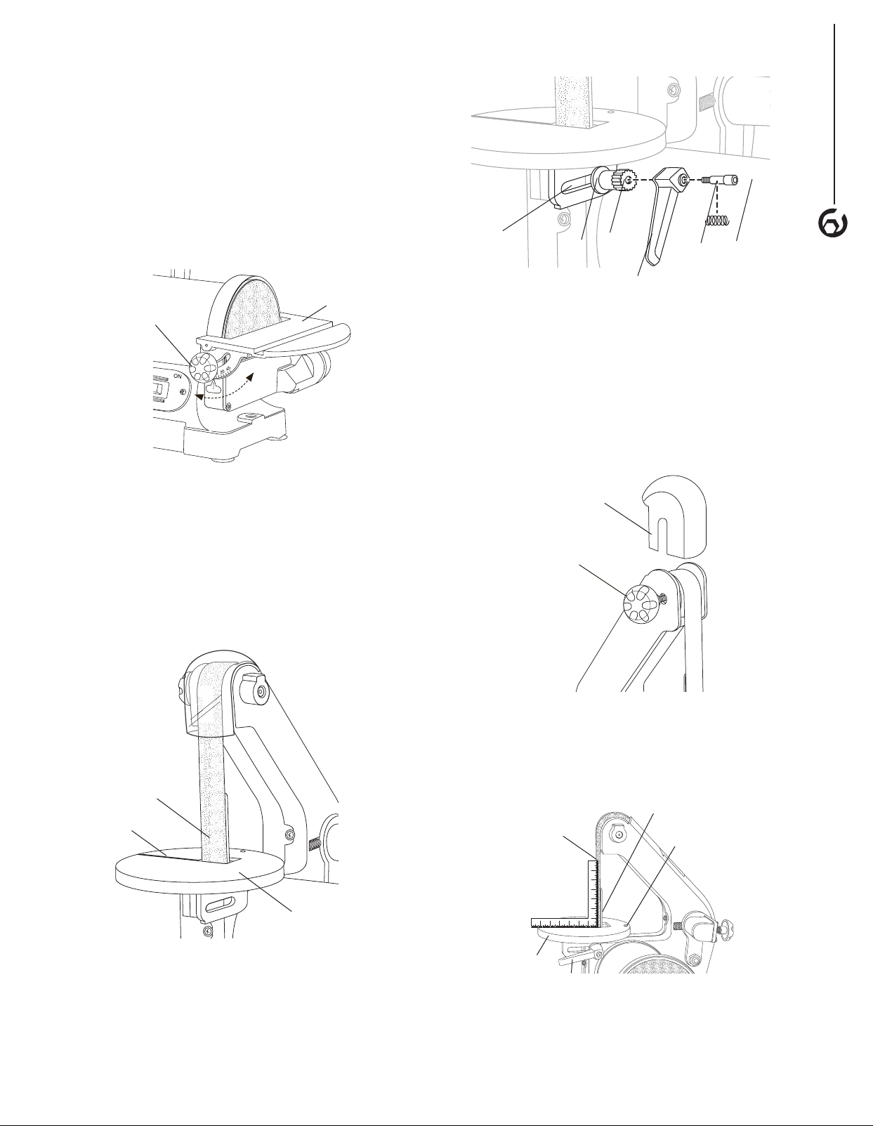
Figure 6
Adjusting
Slot
Washer
Shaft
ScrewSpring
Lever
To adjust sanding belt table:
To square
• If using the backstop, make sure it just touches
the back of the belt. If adjustment is needed, see
Backstop paragraph.
• Remove the upper guard, loosen the lock knob and
slide the guard up and off the belt. See Figure 7.
Figure 7
ASSEMBLY
3
ASSEMBLE THE SANDING BELT TABLE
Refer to Figure 5–9
• Use the 4 mm hex wrench supplied to disassemble the
locking lever assembly. (bolt, spring, lever and shaft,
see Figure 6).
• Pass the sanding belt/backstop through the slot of the
sanding belt table and position the table as shown.
Figure 5
Sanding
Belt
Slot
Upper Belt
Guard
Belt Guard
Lock Knob
• Place a square on the table against the belt as shown.
• Loosen the locking lever assembly and adjust
until square.
• Retighten the locking lever.
Figure 8
Sanding Belt
Backstop
Leveling Screw
Sanding Belt Table
• Use the washer and shaft from the locking lever
assembly to secure the sanding belt table to the frame.
The shaft should be placed at the rear of the adjusting
slot as shown in Figure 6.
• Reassemble the screw, spring and lever to the shaft.
Tighten the locking lever fully to lock the table.
Sanding
Belt
Table
567 4 3 2 1
21 3 4 5 67
Locking
Lever
Page 6

To level
ASSEMBLY
• A leveling screw is provided to aid in leveling the belt
disc table.
• Once the belt table is square, use the 4 mm hex wrench
provided to adjust the hex screw down until it touches
the frame (under the table), then lock the screw in place
by tightening the nut under the table using an 11 mm
wrench.
To set at 45°
If needed the table may be tilted.
4
• Loosen the locking lever until it is very loose.
• Slide locking lever to the front of the adjusting slot as
shown to tilt the table.
• Tighten the lock lever.
After all adjustments are made replace the upper guard
and tighten the lock knob.
Figure 9
• Hold and apply moderate pressure to the belt tracking
knob assembly to release the belt tension enough to
remove the old belt. NOTE: The belt tracking knob is
spring loaded.
Figure 11
Belt
Tracking
Knob
Middle
Wheel
Wheel
Sanding
Belt
Wheel
Sanding Belt
Table
Lever
Adjusting
Slot
REPLACING THE SANDING BELT
Refer to Figure 10, 11
NOTE: This sander uses 1" x 30" sanding belts.
• Turn the machine "OFF", and disconnect the machine
from the power source before assembling the sanding
belt.
• Remove the belt guard locking knob and upper belt
guard. Remove the screws securing the side belt guard
and then remove the side belt guard. See Figure 10.
Figure 10
Upper Belt
Guard
Belt Guard
Locking
Knob
Side Belt
Guard
• Position the new belt on the wheels. Applying pressure
to the belt tracking knob will release tension allowing
the belt to be assembled over the middle wheel. Make
sure the directional arrows on the belt point in the same
direction as the arrows on the sander.
• If needed, turn the belt tracking knob clockwise until the
belt tracks to the center of the wheels.
• Replace the upper, side, and lower guards and secure
in place with the belt guard lock knob and lower
guard screws.
• Ensure the sanding belt table is level. To adjust see
the To Adjust Sanding Belt Table paragraph in this
section.
SANDING BELT TRACKING ADJUSTMENT
Refer to Figure 10, 11
• Turn the machine "OFF", and disconnect the machine
from the power source.
• Remove the belt guard locking knob and upper belt
guard. Remove the screws securing the side belt guard
and then remove the side belt guard. See Figure 10.
• Rotate the sanding belt by hand to check the belt
tracking. The belt should track to the center of
the wheels.
– When looking at the front of the sander if the
belt tracks to the left, turn the tracking knob
counterclockwise until the belt tracks to the center of
the wheels.
– When looking at the front of the sander if the belt
tracks to the right, turn the tracking knob clockwise
until the belt tracks to the center of the wheels.
Page 7

• Replace the upper and side belt guards and secure in
place with the belt guard locking knob.
• Plug the power cord into the correct receptacle.
(Refer to Power Source paragraph in this section of
the manual.)
• Turn the switch ON and OFF to make sure the belt
is tracking at high speed; readjust with tracking knob
if needed.
• Peel the old sanding disc from the sanding wheel. Clean
the sanding wheel with mineral spirits. Make sure the
surface is clean and dry.
• Position the new sanding disc onto the sanding disc and
press into place.
• Reassemble the sanding disc table and dust chute.
Adjust the sanding disc table, if needed. See to Adjust
Sanding Disc Table.
ASSEMBLY
BACKSTOP
Refer to Figure 12
The backstop is a surface to sand against.
To Adjust
• Remove the sanding belt table. See Mount the
Sanding Belt Table paragraph and reverse the order
of assembly.
• Loosen the two screws on backstop and slide the
backstop in or out until it just touches the back of
the belt. Retighten the two screws and replace the
sanding belt table. See Mount the Sanding Belt
Table paragraph.
To Remove
The backstop can be removed for polishing and
contour sanding.
• Remove the sanding belt table. See Mount the
Sanding Belt Table paragraph and reverse the order
of assembly.
• Remove screws and washers securing backstop. Place
screws, washers and backstop in a safe place for future
use.
• Replace the sanding belt table. See Mount the
Sanding Belt Table paragraph.
Figure 12
Backstop
Screws and
Washers
DUST PORT OPTIONS
Refer to Figure 13
The dust ports can be easily connected to a dust
collection system with a large diameter shop
vacuum hose.
Sanding operations are inherently dusty. This sander is
equipped with two 1-3/4” OD x 1-1/2” ID dust ports to help
minimize the amount of dust escaping into the surrounding
air. Attach the dust collection system vacuum hose to the
dust chute.
NOTE: The dust chute is shipped with an adapter for
use with smaller hose dust collectors. This adapter has a
1-1/4” ID and can be used in either dust port.
NOTE: The use of a dust collection system is strongly
recommended when using the belt/disc sander. Use of a
mask or respirator is still recommended even when using
a dust collection system.
Figure 13
Dust Port
Dust Port
Adapter
5
REPLACING THE SANDING DISC
Refer to Figure 2, 3
NOTE: This sander disc uses 5" self adhesive
sanding disc.
• Turn the machine "OFF", and disconnect the machine
from the power source before assembling the
sanding disc.
• Remove the sanding disc locking levers and slide the
sanding disc table from the sander. See Figure 3.
• Remove the screws and washers securing the dust
chute and remove the dust chute from the sander. See
Figure 2.
Dust Port
Dust Port
Adapter
Page 8

MOUNTING THE SANDER TO WORK
ASSEMBLY
SURFACE
Refer to Figure 14
CAUTION
Properly mount the sander to a workbench or stand if
during operation the sander has the tendency to tip over,
slide or walk on the work surface.
• Remove the four rubber feet from the sander.
• Position the sander in place on the work surface. Mark
6
the work surface using the holes in the sander base as a
template. Remove the sander from the work surface.
• Drill holes in the work surface at the marks.
• Secure the sander to the work surface using long bolts,
flat washers and hex nuts (not supplied) as shown.
NOTE: Bolts should be inserted from the top of the
sander and secured underneath the work surface with
flat washers, lock washers and hex nuts. The rubber
feet removed from the sander should be placed between
the sander and the workbench.
Figure 14
Flat Washer
Bolt
Sander
Rubber
Feet
Workbench
GROUNDING INSTRUCTIONS
WARNING
Improper connection of equipment grounding conductor
can result in the risk of electrical shock.
• The machine should be grounded while in use to protect
operator from electrical shock.
• In the event of an electrical short circuit, grounding
reduces the risk of electrical shock by providing an
escape wire for the electric current.
• This machine is equipped with an approved 3-conductor
cord rated at 150V and a 3-prong grounding type plug
for your protection against shock hazards.
• Grounding plug should be plugged directly into a
properly installed and grounded 3-prong grounding-type
receptacle, as shown (Figure 15).
• The plug must be plugged into an outlet that is properly
installed and grounded in accordance with all local
codes and ordinances.
• Check with a qualified electrician or service personnel if
these instructions are not completely understood or if in
doubt as to whether the tool is properly grounded.
• Do not modify plug provided. If it will not fit in outlet,
have proper outlet installed by a qualified electrician.
Use only 3-wire extension cords, that have 3-prong
grounding type plugs and matching 3-conductor
receptacles that accept the machine’s plug, as shown in
Figure 15.
Figure 15
Flat Washer
Hex Nut
POWER SOURCE
WARNING
Do not connect to the power source until the machine is
completely assembled.
The machine is wired for 120 volts, 60 HZ alternating
current. Before connecting the machine to the power
source, make sure the switch is in the “OFF” position.
Running the unit on voltages which are not within range
may cause overheating and motor burn-out. Heavy loads
require that voltage at motor terminals be no less than the
voltage specified on nameplate.
• Power supply to the motor is controlled by a
locking rocker switch. Remove the key to prevent
unauthorized use.
Ground Outlet Box
3-Prong Plug
Grounding Prong
WARNING
Do not permit fingers to touch the terminals of plug when
installing or removing from outlet.
• Inspect tool cords periodically, and if damaged, have
repaired by an authorized service facility.
• The conductor with insulation having an outer surface
that is green with or without yellow stripes is the
equipment-grounding conductor. If repair or replacement
of the electric cord or plug is necessary, do not connect
the green (or green and yellow) wire to a live terminal.
A temporary 3-prong to 2-prong grounding adapter (see
Figure13) may be used to connect this plug to a matching
2-conductor receptacle as shown in Figure 16. The
temporary adapter should be used only until a properly
grounded outlet can be installed by a qualified electrician.
Page 9

Figure 16
Grounded outlet Box
Adapter
In Canada, the use of temporary adapter is not permitted
by the Canadian Electric Code. Where permitted, the rigid
green tab or terminal on the side of the adapter must be
securely connected to a permanent electrical ground such
as a properly grounded water pipe, a properly grounded
outlet box or a properly grounded wire system.
• Many cover plate screws, water pipes and outlet
boxes are not properly grounded. To ensure proper
ground, grounding means must be tested by a
qualified electrician.
Grounding
Means
EXTENSION CORDS
Use proper extension cords. Make sure the extension
cord is in good condition. Use only 3-wire extension cords
have 3-prong grounding type plugs and 3-pole receptacles
which accept the tool plug. When using an extension cord,
make sure to use one heavy enough to carry the current
of the machine. An undersized cord will cause a drop in
the voltage, resulting in loss of power and overheating.
Use the table to determine the minimum wire size
(A.W.G.) extension cord.
Extension Cord Length
• There is a green grounding wire fastened to the frame
of the machine to provide Shock Protection. Do not
disconnect the Grounding Wire from the frame.
• The Motor is rated for use at 120 Volts.
• Connect this machine to 3-Conductor Power outlet with
appropriate rating only.
• Use only 3-pronged Extension Power Cord with
appropriate rating with this machine.
• When changing the power cord, use only 3-pronged
Power Cord with appropriate rating.
• The Power switch is a Single Pole Rocker switch with
Locking Mechanism. Remove the Key when not in use
to prevent accidents.
Figure 17
7
ASSEMBLY
7
Wire Size A.W.G.
Up to 25 ft 16
NOTE:
not recommended.
Using extension cords over 25 ft. long is
MOTOR
The sander is equipped with a 2.3 Amps motor. The
120 Volt motor has the following specifications:
Horsepower .................................................................. 1/3
Voltage .........................................................................120
Amp ...............................................................................2.3
Hertz ...............................................................................60
Phase .......................................................................Single
RPM ............................................................................3450
ELECTRICAL CONNECTIONS
• Turn the switch off and disconnect the machine
from power source before performing any repair or
maintenance work.
• Some electrical wiring and connection work must be
performed by a qualified electrician in accordance with
local regulations.
• Scheme of the motor and electric wiring inside this
machine is shown in Figure 17.
Page 10

8
OPERATION
OPERATION
ON/OFF SWITCH
Refer to Figure 18
• To turn sander ON place the ON/OFF switch in the
ON position.
• To turn the sander OFF, place the ON/OFF switch in the
OFF position.
Figure 18
8
ON/OFF
Switch
SURFACE SANDING ON SANDING BELT
Hold the workpiece firmly with both hands. Keep fingers
away from sanding belt. Keep the workpiece end against
the backstop and move it slowly across the sanding belt.
Apply enough pressure to remove material; excessive
pressure will reduce sanding efficiency.
Figure 19
Slot On Work Table
Miter Gauge
Lock Knob
END SANDING - DISC/BELT
Refer to Figure 19
Use end sanding when sanding the ends of small, narrow
workpieces and outside curved edges.
Always work on the left side of the disc (downward rotation
side), holding the workpiece firmly with light pressure
against the sanding disc.
CAUTION
To avoid personal injury and/or damage to the workpiece,
become familiar with the rotation of the sanding belt and
disc surfaces.
The sanding belt rotates counterclockwise or downward
toward the table or backstop. The sanding disc rotates
counterclockwise, downward toward the work table on the
left side of the sanding disc and upward from the work
table on the right side of the sanding disc. Always use the
left side of the sanding disc; using the right side of the
sanding disc will cause the workpiece to fly up or kickback
and could result in injury.
MITER GAUGE - DISC SANDER
Refer to Figure 19
A miter-gauge is supplied with your sander, and can be
used on the sanding disc table.
• Place the miter gauge slide pole into the slot on the
work table.
• Loosen the miter gauge lock knob and move the miter
gauge head to the left or right to the desired position.
Tighten the miter gauge lock knob. NOTE: The miter
gauge head can be moved right or left 0 to 60º.
NOTE: Use of the miter gauge is recommended for
sanding small end surfaces on the sanding disc.
NOTE: Always move the workpiece across the sanding
disc from the left side towards the right side, and be sure
to hold the workpiece firmly onto the table surface.
CONTOUR SANDING WITH THE BELT
With the backstop removed the sanding belt conforms to a
curved edge for sanding and polishing.
• Remove the backstop. See Backstop under Assembly.
• Turn the sander ON and slowly feed it into the
sanding belt.
8
Page 11

WARNING
MAINTENANCE
WARNING
9
MAINTENANCE
For your own safety, turn the switch OFF and remove
the plug from the electrical outlet before adjusting or
performing maintenance or lubrication work on the
belt/disc sander.
GENERAL MAINTENANCE
Before using, check to make sure parts are not damaged,
missing, or worn; check for alignment of moving parts,
binding of moving parts, improper mounting, or any other
conditions that may affect the sander operation. Should
any of these conditions exist, do not use the
belt/disc sander until properly repaired or parts are
replaced. Frequently blow or vacuum dust from all sanding
parts and motor housing.
Any attempt to repair or replace electrical parts on this tool
may be hazardous. Repairs should be done by a qualified
service technician.
LUBRICATION
Ball bearings are grease packed at the factory and require
no further lubrication. Use a spray lubricant on all moving
table parts to ensure smooth operation.
9
Page 12

10
PARTS LIST
10
1"X 5" BELT/DISC SANDER PARTS ILLUSTRATION
Page 13

1"x 5" BELT/DISC SANDER PARTS LIST
11
PARTS LIST
Key# Part# Description Specifications Qty
1 BD1510001 Philips Screw Assy. M6x18 2
2 BD1510002 Rubber Feet 4
3 BD1510003 Philips Screw Assy. M4x12 4
4 BD1510004 Bottom Cover 1
5 BD1510005 Base 1
6 BD1510006 Switch Box 1
7 BD1510007 Philips Screw M5x10 2
8 BD1510008 End Bell 1
9 BD1510009 Wave Spring Washer 35 1
10 BD1510010 Capacitor 25UF/300V 1
11 BD1510011 Switch 1
12 BD1510012 Philips Screw Assy. M4x8 2
13 BD1510013 Stator 1
14 BD1510014 Cord Clips 6P4 1
15 BD1510015 Power Cord with Plug 1
16 BD1510016 Capacitor Support 1
17 BD1510017 Hex Nut M8 2
18 BD1510018 Hex Nut M6 1
19 BD1510019 Belt Guard 1
20 BD1510020 Rotor 1
21 BD1510021 Philips Screw M4x8 1
22 BD1510022 Belt Limited Plate 1
23 BD1510023 Flat Washer D4 5
24 BD1510024 Inner Hex Socket Cap
Screw
25 BD1510025 Guard Locking Knob 1
26 BD1510026 Belt Guard Cover 1
27 BD1510027 Belt Support Cover 1
28 BD1510028 Belt 100# 1”x30” 1
29 BD1510029 Driven Pulley 2
30 BD1510030 Circlip for Shaft D15 2
31 BD1510031 Bearing 6202 4
32 BD1510032 Driven Shaft 1
33 BD1510033 Inner Hex Set Screw M6x8 1
34 BD1510034 Philips Screw Assy. M5x16 Left 1
35 BD1510035 Adaptor 1
36 BD1510036 Driving Wheel 1
37 BD1510037 Philips Screw M6x10 3
M4x10 2
Key# Part# Description Specifications Qty
38 BD1510038 Hex Bolt M10x25 1
39 BD1510039 Belt Support 1
40 BD1510040 Inner Hex Set Screw M6x20 1
41 BD1510041 Belt Work Table 1
42 BD1510042 Big Flat Washer D8 1
43 BD1510043 Locking Knob Assy. 1
44 BD1510044 Guard for Adjustable Shaft 1
45 BD1510045 Adjustable Spring 1
46 BD1510046 Locking Nut M10 1
47 BD1510047 Adjustable Fixed Plate 1
48 BD1510048 Adjustable Spring I 1
49 BD1510049 Adjustable Knob 1
50 BD1510050 Philips Self Screw ST4.2x16 4
51 BD1510051 Elastic Cylindrical Pin φ3x20 1
52 BD1510052 Adjustable Shaft 1
53 BD1510053 Adjustable Spring II 1
54 BD1510054 Big Flat Washer D5 2
55 BD1510055 Split Washer 3.5 1
56 BD1510056 Disc Cover 1
57 BD1510057 Pointer 1
58 BD1510058 Tooth Lock Washer D4 1
59 BD1510059 Philips Screw M4x6 1
60 BD1510060 Index Plate Handle 1
61 BD1510061 Hex Flange Nut M4 4
62 BD1510062 Index Plate for Work Rest 1
63 BD1510063 Miter Gauge 1
64 BD1510064 Disc Work Table 1
65 BD1510065 Flat Washer D6 2
66 BD1510066 Locking Knob for Work
67 BD1510067 Disc Paper 80# 5” 1
68 BD1510068 Inner Hex Socket Cap
69 BD1510069 Philips Screw M4x8 3
70 BD1510070 Disc 1
71 BD1510071 End Bell Of Disc Cover 1
72 BD1510072 Philips Screw Assy. M4x153 4
73 BD1510073 Philips Screw Assy. M4x8 3
Table
M6x16 1
Screws Assp.
11
2
Page 14

12
SYMPTOM POSSIBLE CAUSE(S) CORRECTIVE ACTION
Sanding Grains
TROUBLESHOOTING
easily rub off belt
or discs.
Deep sanding
grooves or scars
in workpiece.
12
Sanding surface
clogs quickly.
Burns on workpiece. 1. Using a sanding grit that is
Motor will not start –
fuses or circuit
breakers tripping
or blowing.
Motor overheats. 1. Motor overloaded.
Motor stalls
(resulting in blown
fuses or tripped
circuit).
Machine slows
when operating.
Machine
vibrates excessively.
Workpiece frequently
gets pulled out of
operator’s hands.
Workpiece lifts up
from the sanding
disc/table.
TROUBLESHOOTING
1. Sanding belt/disc has been stored
in an incorrect environment.
2. Sanding belt/disc has been
damaged or folded.
1. Sanding belt/disc grit is too
coarse for the desired finish.
2. Workpiece sanded across
the grain.
3. Too much sanding force on the
workpiece.
4. Workpiece held still against the
belt/disc for too long.
1. Too much pressure against belt/
disc.
2. Sanding softwood.
too fine.
2. Using too much pressure.
3. Work held still for too long.
1. Short circuit in line, cord or plug.
2. Short circuit in motor or loose
connections.
3. Incorrect fuses or circuit breakers
in power line.
2. Extension cord too long and of
insufficient gauge (weight).
1. Short circuit in motor or loose
connections.
2. Low voltage.
3. Incorrect fuses or circuit breakers
in power line.
4. Motor overload.
1. Feed rate too great.
2. Undersized circuit or use of
undersized extension cord.
1. Rubber feet worn, mounting
hardware loose
2. Workbench or table is not level
3. Worn bearings
1. Not supporting the workpiece
against the stop.
2. Attempting to sand (unaided) a
workpiece that is too small.
Sanding on the “up” side wheel. Sand on right side of sanding disc (as operator faces
1. Ensure sanding accessories are stored away from
extremely hot or dry temperatures.
2. Store sanding accessories flat – not bent or
folded.
1. Use a finer-grit sanding accessory.
2. Sand with the grain of the wood.
3. Reduce pressure on workpiece while sanding.
4. Keep workpiece moving while sanding on the
sanding accessory.
1. Reduce pressure on workpiece while sanding.
2. Use different stock, different sanding accessories,
or accept that this will happen and plan on
cleaning or replacing discs/belts frequently.
1. Use a coarser-grit sanding accessory.
2. Reduce pressure on workpiece while sanding.
3. Do not keep workpiece in one place for too long.
1. Inspect cord or plug for damaged insulation and
shorted wires.
2. Inspect all connections on motor for loose or
shorted terminals and/or worn insulation.
3. Install correct fuses or circuit breakers or switch
tool to an appropriately size circuit.
1. Reduce load on motor (pressure on object being
sanded).
2. Utilize an extension cord of appropriate gauge and
length or plug tool directly into outlet.
1. Inspect connections on motor for loose or shorted
terminals or worn insulations.
2. Correct low voltage conditions (for example:
improper extension cord length and/or gauge).
3. Install CORRECT fuses or circuit breakers or plug
tool into an appropriate circuit, matched to an
appropriate fuse or breaker.
4. Reduce the load on the motor.
1. Reduce the rate at which the workpiece is fed into
the working area of the tool.
2. Ensure circuit wires or extension cords are proper
gauge, or eliminate use of extension cords.
1. Replace the rubber feet, tighten mounting
hardware
2. Shim or adjust as need
3. Have bearings replaced by service technician.
1. Use the platen (backstop) or miter gauge to
support the workpiece.
2. Use another hand tool or jig to grasp or hold
the workpiece.
the disc).
Page 15

WARRANTY
Thank you for investing in a POWERTEC power tool. This product has been designed and manufactured to meet high
quality standards and is guaranteed for domestic use against defects in workmanship or material for a period of 12
months from the date of purchase. This guarantee does not affect your statutory rights.
SOUTHERN TECHNOLOGIES LLC. BENCH TOP AND STATIONARY POWER TOOL
LIMITED 1 YEAR WARRANTY AND 30-DAY SATISFACTION GUARANTEE POLICY
POWERTEC products are designed and manufactured by Southern Technologies LLC. All warranty communications
should be directed to Southern Technologies LLC by calling 847-780-6120, 9 AM to 5 PM, Monday through Friday,
US Central Time.
30- DAY SATISFACTION GUARANTEE POLICY
During the first 30 days after the date of purchase, if you are dissatisfied with the performance of this POWERTEC tool
for any reason, you may return the tool to the retailer from which it was purchased for a full refund or exchange. You
must present proof of purchase and return all original equipment packaged with the original product. The replacement
tool will be covered by the limited warranty for the remainder of the one year warranty period.
LIMITED ONE YEAR WARRANTY
This warranty covers all defects in workmanship or materials in this POWERTEC tool for a one year period from the
date of purchase. This warranty is specific to this tool. Southern Technologies, LLC reserves the right to repair or
replace the defective tool, at its discretion.
13
WARRANTY
13
HOW TO OBTAIN SERVICE
To obtain service for this POWERTEC tool you must return it, freight prepaid, to POWERTEC. You may call (toll
free) 847-780-6120 for more information. When requesting warranty service, you must present proof of purchase
documentation, which includes a date of purchase. POWERTEC will either repair or replace any defective part, at
our option at no charge to you. The repaired or replacement unit will be covered by the same limited warranty for the
remainder of the one year warranty period.
WHAT IS NOT COVERED
This warranty applies to the original purchaser at retail and may not be transferred.
This warranty does not cover consumable items such as saw blades, knives, belts, discs, cooling blocks and sleeves.
This warranty does not cover required service and part replacement resulting from normal wear and tear, including
accessory wear.
This warranty does not cover any malfunction, failure or defect resulting from:
1) misuse, abuse, neglect and mishandling not in accordance with the owner's manual.
2) damage due to accidents, natural disasters, power outage, or power overload.
3) commercial or rental use.
4) alteration, modification or repair performed by persons not recommended by POWERTEC.
DISCLAIMER
To the extent permitted by applicable law, all implied warranties, including warranties of MERCHANTABILITY or
FITNESS FOR A PARTICULAR PURPOSE, are disclaimed. Any implied warranties, that cannot be disclaimed under
state law are limited to one year from the date of purchase. Southern Technologies LLC. is not responsible for direct,
indirect, incidental or consequential damages. Some states do not allow limitations on how long an implied warranty
lasts and/or do not allow the exclusion or limitation of incidental or consequential damages, so the above limitations may
not apply to you. This warranty gives you specific legal rights, and you may also have other rights which vary from state
to state. Southern Technologies LLC., makes no warranties, representations, or promises as to the quality or
performance of its power tools other than those specifically stated in this warranty.
Page 16

Southern Technologies, LLC
3816 Hawthorn CT,
Waukegan, IL 60087
 Loading...