

Page 1
IM3030
04/2011
REV01
POWERTEC
365S, 425S & 505S
OPERATOR’S MANUAL
LINCOLN ELECTRIC BESTER Sp. z o.o
ul. Jana III Sobieskiego 19A, 58-260 Bielawa, Poland
www.lincolnelectric.eu
Page 2

II
Declaration of conformity
LINCOLN ELECTRIC BESTER Sp. z o.o.
Declares that the welding machine:
POWERTEC 365S, 425S, 505S
conforms to the following directives:
2006/95/CEE, 2004/108/CEE
and has been designed in compliance with the following
standards:
EN 60974-1, EN 60974-10
(2005)
Paweł Lipiski
Operations Director
LINCOLN ELECTRIC BESTER Sp. z o.o., ul. Jana III Sobieskiego 19A, 58-260 Bielawa, Poland
04/11
Page 3

III
07/06
Do not dispose of electrical equipment together with normal waste!
In observance of European Directive 2002/96/EC on Waste Electrical and Electronic Equipment (WEEE) and its
implementation in accordance with national law, electrical equipment that has reached the end of its life must be
collected separately and returned to an environmentally compatible recycling facility. As the owner of the
equipment, you should get information on approved collection systems from our local representative.
By applying this European Directive you will protect the environment and human health!
Page 4

IV
12/05
THANKS! For having choosen the QUALITY of the Lincoln Electric products.
• Please Examine Package and Equipment for Damage. Claims for material damaged in shipment must be notified
immediately to the dealer.
• For future reference record in the table below your equipment identification information. Model Name, Code & Serial
Number can be found on the machine rating plate.
Model Name:
………………...…………………………….…………………………………………………………………………………………..
Code & Serial number:
………………….……………………………………………….. …………………………………………………….……………..
Date & Where Purchased:
…………………………………………………………………... ……………………….…………………………………………..
INDEX
Safety............................................................................................................................................................................................... A-1
Installation and Operator Instructions ............................................................................................................................................... A-2
Electromagnetic Compatibility (EMC) ...............................................................................................................................................A-5
Technical Specifications................................................................................................................................................................... A-6
Spare Parts ..........................................................................................................................................................................................1
Electrical Schematic.............................................................................................................................................................................7
Accessories..........................................................................................................................................................................................9
Page 5
A-1
Safety
11/04
WARNING
This equipment must be used by qualified personnel. Be sure that all installation, operation, maintenance and repair
procedures are performed only by qualified person. Read and understand this manual before operating this equipment.
Failure to follow the instructions in this manual could cause serious personal injury, loss of life, or damage to this
equipment. Read and understand the following explanations of the warning symbols. Lincoln Electric is not responsible
for damages caused by improper installation, improper care or abnormal operation.
WARNING: This symbol indicates that instructions must be followed to avoid serious personal injury,
loss of life, or damage to this equipment. Protect yourself and others from possible serious injury or
death.
READ AND UNDERSTAND INSTRUCTIONS: Read and understand this manual before operating
this equipment. Arc welding can be hazardous. Failure to follow the instructions in this manual could
cause serious personal injury, loss of life, or damage to this equipment.
ELECTRIC SHOCK CAN KILL: Welding equipment generates high voltages. Do not touch the
electrode, work clamp, or connected work pieces when this equipment is on. Insulate yourself from
the electrode, work clamp, and connected work pieces.
ELECTRICALLY POWERED EQUIPMENT: Turn off input power using the disconnect switch at the
fuse box before working on this equipment. Ground this equipment in accordance with local electrical
regulations.
ELECTRICALLY POWERED EQUIPMENT: Regularly inspect the input, electrode, and work clamp
cables. If any insulation damage exists replace the cable immediately. Do not place the electrode
holder directly on the welding table or any other surface in contact with the work clamp to avoid the
risk of accidental arc ignition.
ELECTRIC AND MAGNETIC FIELDS MAY BE DANGEROUS: Electric current flowing through any
conductor creates electric and magnetic fields (EMF). EMF fields may interfere with some
pacemakers, and welders having a pacemaker shall consult their physician before operating this
equipment.
CE COMPLIANCE: This equipment complies with the European Community Directives.
FUMES AND GASES CAN BE DANGEROUS: Welding may produce fumes and gases hazardous to
health. Avoid breathing these fumes and gases. To avoid these dangers the operator must use
enough ventilation or exhaust to keep fumes and gases away from the breathing zone.
ARC RAYS CAN BURN: Use a shield with the proper filter and cover plates to protect your eyes from
sparks and the rays of the arc when welding or observing. Use suitable clothing made from durable
flame-resistant material to protect you skin and that of your helpers. Protect other nearby personnel
with suitable, non-flammable screening and warn them not to watch the arc nor expose themselves to
the arc.
WELDING SPARKS CAN CAUSE FIRE OR EXPLOSION: Remove fire hazards from the welding
area and have a fire extinguisher readily available. Welding sparks and hot materials from the welding
process can easily go through small cracks and openings to adjacent areas. Do not weld on any
tanks, drums, containers, or material until the proper steps have been taken to insure that no
flammable or toxic vapors will be present. Never operate this equipment when flammable gases,
vapors or liquid combustibles are present.
WELDED MATERIALS CAN BURN: Welding generates a large amount of heat. Hot surfaces and
materials in work area can cause serious burns. Use gloves and pliers when touching or moving
materials in the work area.
SAFETY MARK: This equipment is suitable for supplying power for welding operations carried out in
an environment with increased hazard of electric shock.
Page 6
A-2
CYLINDER MAY EXPLODE IF DAMAGED: Use only compressed gas cylinders containing the
correct shielding gas for the process used and properly operating regulators designed for the gas and
pressure used. Always keep cylinders in an upright position securely chained to a fixed support. Do
not move or transport gas cylinders with the protection cap removed. Do not allow the electrode,
electrode holder, work clamp or any other electrically live part to touch a gas cylinder. Gas cylinders
must be located away from areas where they may be subjected to physical damage or the welding
process including sparks and heat sources.
Installation and Operator Instructions
Read this entire section before installation or operation
of the machine.
Location and Environment
This machine will operate in harsh environments.
However, it is important that simple preventative
measures are followed to assure long life and reliable
operation:
• Do not place or operate this machine on a surface
with an incline greater than 15° from horizontal.
• Do not use this machine for pipe thawing.
• This machine must be located where there is free
circulation of clean air without restrictions for air
movement to and from the air vents. Do not cover
the machine with paper, cloth or rags when
switched on.
• Dirt and dust that can be drawn into the machine
should be kept to a minimum.
• This machine has a protection rating of IP23. Keep
it dry when possible and do not place it on wet
ground or in puddles.
• Locate the machine away from radio controlled
machinery. Normal operation may adversely affect
the operation of nearby radio controlled machinery,
which may result in injury or equipment damage.
Read the section on electromagnetic compatibility in
this manual.
• Do not operate in areas with an ambient
temperature greater than 40°C.
Duty cycle and Overheating
The duty cycle of a welding machine is the percentage of
time in a 10 minute cycle at which the welder can
operate the machine at rated welding current.
Example: 60% duty cycle:
Welding for 6 minutes. Break for 4 minutes.
Excessive extension of the duty cycle will cause the
thermal protection circuit to activate.
The welding transformer in the machine is protected
from overheating by a thermostat. When the machine is
overheated the output of the machine will turn “OFF“,
and the Thermal Indicator Light will turn “ON“. When the
machine has cooled to a safe temperature the Thermal
Indicator Light will go out and the machine may resume
normal operation. Note: For safety reasons the machine
will not come out of thermal shutdown if the trigger on
the welding gun has not been released.
Minutes or decrease
duty cycle
Input Supply Connection
Installation and mains outlet socket shall be made and
protected according to appropriate rules.
Check the input voltage, phase, and frequency supplied
to this machine before turning it on. Verify the
connection of grounding wires from the machine to the
input source. The allowable input voltages are 3x220V,
3x380V and 3x440V 50/60Hz (440V: factory default).
For more information about input supply refer to the
technical specification section of this manual and to the
rating plate of the machine.
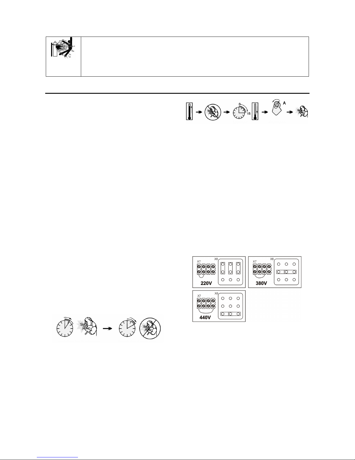
If it is necessary to change the input voltage:
• The input cable must be disconnected from the
mains supply and the machine switched OFF.
• Remove the big side cover from the machine.
• Reconnect X6 and X7 according to the diagram
below:
• Replace the big side cover.
Make sure that the amount of mains power available
from the input supply is adequate for normal operation of
the machine. The necessary delayed fuse (or circuit
breaker with ”D” characteristic) and cable sizes are
indicated in the technical specification section of this
manual.
Refer to points [1] and [13] of the images below.
Output Connections
Refer to points [3], [6] and [7] of the images below.
Page 7

A-3
Controls and Operational Features
1. Power Switch and Power Indicator: After input
power is connected and the power switch is turned
on, the indicator will light up to indicate the machine
is ready to weld.
2. Welding Voltage Changing Switches. The
POWERTEC 365S, 425S and 505S have 2
switches (3 and 10 steps).
3. Positive Output Socket: Allows the connection, with
the power cable, to the wire feeder.
4. Wire Feeder Receptacle: 14-pins receptacle for
wire feeder. Provides connections for auxiliary
power of wire feeder. Use source/wire feeder cable
K10347-PG-xxM series or K10347-PGW-xxM
series.
5. Wire Feeder Voltmeter Switch: This switch selects
the polarity of the wire feeder voltmeter, if so
equipped. When welding torch is positive (MIG,
Outershield and some Innershield processes), set
the switch to “+”. When welding torch is negative
(most Innershield applications), set the switch to “-“.
6. Output Socket with Low Inductance: For connecting
the return welding cable.
7. Output Socket with High Inductance: For
connecting the return welding cable.
8. Fuse: This fuse protects the gas heater socket (see
accessories, K14009-1 CO2 Socket Kit).
9. Fuse: This fuse protects the primary winding of
auxiliary transformer.
10. Covered Hole: For CO2 gas heater socket (see
accessories, K14009-1 CO2 Socket Kit).
11. Cooler Power Supply Socket: For supplying the
cooler unit. The socket has an intermittent output of
230V, 2.5A and is protected by the circuit breaker
[13]. See point [14] for more details.
12. Power Input Cable: Connect the proper plug to the
input cable then into the rated output according to
appropriate rules. Only qualified personnel shall
connect this plug.
13. Circuit Breaker: Protect the Cooler Power Supply
socket [12]. It shuts off the power supply when the
current exceeds 2.5A. Press it to restore the power
supply.
Welding Cables Connections
Insert the plug of the work cable into the socket [6] or [7].
The other end of this cable connects to the work piece
with the work clamp.
Connect the wire feeder to the power source:
• insert the positive welding cable into the output
socket [3].
• insert the wire feeder control cable into the
socket [4].
Use the shortest possible cable lengths.
Page 8

A-4
Setting Welding Voltage
Maintenance
WARNING
For any maintenance or repair operations it is
recommended to contact the nearest Technical Service
Center or Lincoln Electric. Maintenance or repairs
performed by unauthorized service centers or personnel
will null and void the manufacturer's warranty.
The frequency of the maintenance operations may vary
in accordance with the working environment where the
machine is placed.
Any noticeable damage should be reported immediately.
Routine maintenance (everyday)
• Check cables and connections integrity. Replace, if
necessary.
• Remove the spatters from the welding gun nozzle.
Spatters could interfere with the shielding gas flow
to the arc.
• Check the welding gun condition: replace it, if
necessary.
• Check condition and operation of the cooling fan.
Keep clean its airflow slots.
Periodic maintenance (every 200 working hours
but at list once every year)
Perform the routine maintenance and, in addition:
• Keep the machine clean. Using a dry (and low
pressure) airflow, remove the dust from the external
case and from the cabinet inside.
• Check and tighten all screws.
WARNING
Mains supply network must be disconnected from the
machine before each maintenance and service. After
each repair, perform proper tests to ensure safety.
Transport
WARNING
To ensure safety transport it is necessary to:
• lift only power source without gas cylinder, cooler
and wire feeder,
• screw down an eye bolt and apply load axially in 45
degree angle in accordance to the drawing.
• ensure equal length of lifting lines.
Page 9

A-5
Electromagnetic Compatibility (EMC)
11/04
This machine has been designed in accordance with all relevant directives and standards. However, it may still generate
electromagnetic disturbances that can affect other systems like telecommunications (telephone, radio, and television) or
other safety systems. These disturbances can cause safety problems in the affected systems. Read and understand
this section to eliminate or reduce the amount of electromagnetic disturbance generated by this machine.
This machine has been designed to operate in an industrial area. To operate in a domestic area it is
necessary to observe particular precautions to eliminate possible electromagnetic disturbances. The
operator must install and operate this equipment as described in this manual. If any electromagnetic
disturbances are detected the operator must put in place corrective actions to eliminate these disturbances
with, if necessary, assistance from Lincoln Electric.
Before installing the machine, the operator must check the work area for any devices that may malfunction because of
electromagnetic disturbances. Consider the following.
• Input and output cables, control cables, and telephone cables that are in or adjacent to the work area and the
machine.
• Radio and/or television transmitters and receivers. Computers or computer controlled equipment.
• Safety and control equipment for industrial processes. Equipment for calibration and measurement.
• Personal medical devices like pacemakers and hearing aids.
• Check the electromagnetic immunity for equipment operating in or near the work area. The operator must be sure
that all equipment in the area is compatible. This may require additional protection measures.
• The dimensions of the work area to consider will depend on the construction of the area and other activities that are
taking place.
Consider the following guidelines to reduce electromagnetic emissions from the machine.
• Connect the machine to the input supply according to this manual. If disturbances occur if may be necessary to take
additional precautions such as filtering the input supply.
• The output cables should be kept as short as possible and should be positioned together. If possible connect the
work piece to ground in order to reduce the electromagnetic emissions. The operator must check that connecting
the work piece to ground does not cause problems or unsafe operating conditions for personnel and equipment.
• Shielding of cables in the work area can reduce electromagnetic emissions. This may be necessary for special
applications.
Page 10

A-6
Technical Specifications
POWERTEC 305S, 365S, 425S & 505S:
INPUT
Input Power at Rated Output
365S:
16 kVA @ 40% Duty Cycle
425S:
21 kVA @ 40% Duty Cycle
Input Voltage
220 / 380 / 440V ± 10%
Three Phase
505S:
29.9 kVA @ 40% Duty Cycle
Frequency
50/60 Hertz (Hz)
RATED OUTPUT AT 40°C
Duty Cycle
(
Based on a 10 min. period
)
Output Current
Output Voltage
365S:
40%
60%
100%
350A
285A
220A
31.5 Vdc
28.2 Vdc
25.0 Vdc
425S:
40%
60%
100%
420A
345A
265A
35.0 Vdc
31.3 Vdc
27.3 Vdc
505S:
40%
60%
100%
500A
400A
315A
39.0 Vdc
34.5 Vdc
29.8 Vdc
OUTPUT RANGE
Welding Current Range
Maximum Open Circuit Voltage
365S:
30A - 350A
365S:
42 Vdc
425S:
30A - 420A
425S:
47 Vdc
505S:
30A - 500A
505S:
55 Vdc
RECOMMENDED INPUT CABLE AND FUSE SIZES
Fuse or Circuit Breaker Size
Input Power Cable
365S:
40A (for 220V) Superlag
25A (for 380V) Superlag
25A (for 440V) Superlag
365S:
4 Conductor, 4mm2
425S:
50A (for 220V) Superlag
32A (for 380V) Superlag
32A (for 440V) Superlag
425S:
4 Conductor, 6mm2
505S:
63A (for 220V) Superlag
40A (for 380V) Superlag
40A (for 440V) Superlag
505S:
4 Conductor, 6mm2
PHYSICAL DIMENSIONS
Height
Width Length Weight
365S:
875 mm 700 mm 1035 mm 141 kg
425S:
875 mm 700 mm 1035 mm 151 kg
505S:
875 mm 700 mm 1035 mm 157 kg
Operating Temperature
-10°C to +40°C
Storage Temperature
-25°C to +55°C
Page 11

1
Spare Parts
12/05
Part List reading instructions
• Do not use this part list for a machine if its code number is not listed. Contact the Lincoln Electric Service Department for any
code number not listed.
• Use the illustration of assembly page and the table below to determine where the part is located for your particular code
machine.
• Use only the the parts marked "X" in the column under the heading number called for in the assembly page (# indicate a change
in this printing).
Page 12

2
SP50149/50151/50153 REV01
04/11
POWERTEC 365S, 425S & 505S
Assembly Figure
Code NO. K NO. Product Name A B C
50149 K14061-2A POWERTEC 365S 1 1 1
50151 K14062-2A POWERTEC 425S 2 2 2
50153 K14063-2A POWERTEC 505S 3 3 3
Figure A
Figure A
No. Description Index Qty. 1 2 3
1 BLACK FRAME SHIELD 1115-299-073R 1 x x x
2 SWITCH 1115-270-019R 1 x x x
3 FEMALE SOCKET 1158-641-130R 1 x x x
4 SWITCH 1158-650-023R 1 x x x
5 SOCKET C-2986-001-3R 3 x x x
6 CASTER DIA 1029-660-127R 2 x x x
7 SUPPORT R-1019-160-1/08R 1 x x x
8 BASE R-1019-150-1/08R 1 x x x
9 SHELF R-3019-142-1/08R 1 x x x
10 DIVIDER R-3019-143-1/08R 1 x x x
11 SHELF R-3019-026-1/08R 1 x x x
12 WHEEL 1029-660-250R 2 x x x
13 BACK PANEL R-3019-144-1/08R 1 x x x
Page 13

3
14 SUPPORT R-1019-153-1/08R 1 x x x
15 COVER R-1019-164-1/02R 1 x x x
16 STICKER R-0010-279-1R 1 x x x
17 ROTARY BRACKET 1361-598-181R 1 x x x
18 STICKER 2719-107-728R 1 x x x
19 BRACKET R-3019-093-1/08R 1 x x x
CAM SWITCH 1115-260-074R 1 x x * 20
CAM SWITCH 1115-260-224R 1 * * x
CAM SWITCH 1115-260-073R 1 x x * 21
CAM SWITCH 1115-260-223R 1 * * x
22 FRONT PANEL R-3019-145-1/08R 1 x x x
23 STICKER R-0010-218-1R 1 x x x
24 COVER R-1019-161-1/02R 1 x x x
STICKER R-0010-234-1R 1 x * *
STICKER R-0010-235-1R 1 * x *
25
STICKER R-0010-236-1R 1 * * x
Figure B
Figure B
No. Description Index Qty. 1 2 3
TRANSFORMER R-4034-092-1R 1 x * *
TRANSFORMER R-4034-093-1R 1 * x *
1
TRANSFORMER R-4034-094-1R 1 * * x
2 FAN R-8040-055-3R 1 x x x
3 PARTITION R-3019-135-1/08R 1 x x x
3-PHASE RECTIFIER R-0010-241-1R 1 x * *
3-PHASE RECTIFIER R-0010-242-1R 1 * x *
4
3-PHASE RECTIFIER R-0010-243-1R 1 * * x
Page 14

4
5 CHOKE R-4034-091-1/85R 1 x x x
6 BRACKET R-1019-176-2/08R 1 x x x
7 BRACKET R-1019-176-1/08R 1 x x x
8 BRACKET R-1019-175-1/08R 1 x x x
9 SHELF R-3019-142-1/08R 1 x x x
10 DIVIDER R-3019-143-1/08R 1 x x x
11 RELAY BASE 1158-632-017R 1 x x x
12 RELAY 0918-412-065R 1 x x x
CONTACTOR CI-42 1115-212-242R 1 x x *
13
CONTACTOR CI-50 1115-212-243R 1 * * x
14 TRANSFORMER C-4244-384-1R 1 x x x
15 RC-FILTER 0874-400-011R 1 x x x
16 CAPACITOR 1158-121-001R 1 x x x
17 STICKER R-0010-287-1R 1 x x x
18 TERMINAL BLOCK 0744-000-069R 1 x x x
POWER CABLE D-5578-171-2R 1 x * *
19
POWER CABLE D-5578-171-3R 1 * x x
Figure C.
Figure C
No. Description Index Qty. 1 2 3
1 PANEL R-1019-157-1/08R 1 x x x
2 STICKER R-0010-239-1R 1 x x x
3 HOLE PLUG 1361-559-058R 1 x x x
4 HOLE PLUG 1119-510-005R 1 x x x
5 SOCKET 1-PHASE 1131-222-004R 1 x x x
6 FUSE HOUSING 1115-299-027R 1 x x x
7 FUSE SOCKET 1158-632-032R 1 x x x
WELDING CABEL D-5578-176-4R 1 x x *
8
WELDING CABEL R-5041-024-1R 1 * * x
Miscellaneous item (not showed in figure A,B,C)
No. Description Index Qty. 1 2 3
1 WIRNING HARNESS A (PRIMARY) R-5041-142-2R 1 x x x
2 WIRNING HARNESS A (PRIMARY) R-5041-143-2R 1 x x x
3
WIRNING HARNESS
(SECONDARY)
R-5041-159-1R 1 x x x
4 WIRNING HARNESS R-5041-157-1R 1 x x x
Page 15

5
Waste Electrical & Electronic Equipment
Page 16

6
Recycle ST
Ref. Fe Al. Cu Brass
Boards Plastics Liquid
Cristal
External
Electric
Cables
Capa
citors
Front Panel Assembly
1 X
Base Assembly 2 X
Right Side Access
Panel 3 X
Left Side Panel 4 X
Rear Panel Assembly 5 X
Panel Assembly 6 X
Top Panel Assembly 7 X
Divider Panel Assebly
8 X
3-phase Bridge
Rectifier
9 X X
Auxiliary Transformer 10 X X X
Bracket
11,12,13,1
4 X
Bus Bar 15 X X
Cables 16,17 X X X X
Capacitor 18 X
Chain 19 X
Choke 20 X X X
Contactor 21 X X X
Control Socket 22 X
Cover 23 X
Fan Assembly 24 X X
Lug Screws 25 X
Main Transformer 26 X X X
RC Filter 27 X X
Relay 28 X X X
Shelf 29 X
Switches
30, 31, 32,
33 X X
Terminal Blocks 34 X X
Welding Socket 35 X X
Wheels 36,37 X X
Page 17

7
Electrical Schematic
Page 18

8
Page 19

9
Accessories
K10347-PG-xM Source/wire feeder cable (gas). Available in 5, 10 or 15m.
K10347-PGW-xM Source/wire feeder cable (gas and water). Available in 5, 10 or 15m.
K14009-1
CO
2
Socket Kit.
KP14016-0.8
KP14016-1.0
KP14016-1.2
Solid:
0,6-0,8mm
0,8-1,0mm
1,0-1,2mm
KP14016-1.6R Cored wires:
1.2-1.6mm
KP14016-1.2A Aluminum wires:
1,0-1,2mm
KP14017-0.8
KP14017-1.0
KP14017-1.2
KP14017-1.6
Solid wires:
0,6-0,8mm
0,8-1,0mm
1,0-1,2mm
1,2-1,6mm
KP14017-1.6R
KP14017-2.4R
Cored wires:
1.2-1.6mm
1.6-2.4mm
KP14017-1.2A
KP14017-1.6A
Aluminum:
1,0-1,2mm
1,2-1,6mm
K14032-1 Heavy duty undercarriage wheels kit.
Page 20

10
MANUAL REVISIONS
DO NOT PRINT THIS PAGE IN THE MANUAL.
REV 0:
• Beta phase Manual English / Portuguese.
REV01
Spare parts was changed.
Title page and page II were changed.
PRINT THIS MANUAL ACCORDINGLY WITH THE PROCEDURE DT0052.
 Loading...