

Page 1

Model
1000AR
Regenerative
Brushless DC Motor Control
NSTALLATION AND
I
PERATION
O
NSTRUCTION MANUAL
I
J
UNE
, 2001
Page 2

Model
1000AR
Installation and Operation Manual
NTRODUCTION
I
P
AGE
1
WHAT IS A GENESIS SERIES BRUSHLESS DC DRIVE ?
The GENESIS series of Brushless DC (BLDC) motor controls (drives) were developed to operate very
large Brushless DC motors. Large BLDC motors were first made by POWERTEC Industrial Corporation in the
late 1980’s. POWERTEC was acquired by Powertec in 1993.
Small BLDC motors have been in use for many years. The GENESIS series were the first drives
produced to operate really large BLDC motors. They range from fractional Horsepower (HP) to 300 HP.
Brushless DC motors and drives offer three significant benefits to the user:
Absolute Speed Control
High Efficiency
Low Maintenance.
ABSOLUTE SPEED CONTROL
The AC induction motor must slow down, or “slip”, in order to develop torque. The amount of slip varies
with the load on the motor. When the load changes from no load to full load, speed may change by as much
as 50 RPM. You must use extraordinary means to employ AC motors in speed sensitive applications.
Traditional brush-type DC motors have “IR Losses” that causes the speed of the motor to vary as the
load changes. “IR Losses” cause speed changes of as much as 2% of base speed. You can limit speed
changes to about 0.5% with a very expensive tachometer. That is still 8 or 9 RPM from no load to full load.
You must use extraordinary means to employ brush-type DC motors in speed sensitive applications.
Brushless DC drives and motors do not change speed when the load changes. This is true with the
standard product
, right out of the box! This is very good for speed sensitive applications.
HIGH EFFICIENCY
AC induction motors are relatively efficient when operated across the line on plant power. Using an AC
variable speed inverter to control the speed of the motor adds power losses as heat in the drive. It also
creates additional losses in the motor. At the 100HP level, the total losses in the AC system approach 10%.
Brush-type DC motor systems at 100 HP are relatively efficient, but the losses total about 8%.
Brushless DC systems at the 100 HP level average less than 6%.
At 100 HP, each percentage of losses is 750 watts. That’s 18 KiloWatt-Hours (KWH) per day, or about
6,500 KWH per year. A 2% difference in efficiency results in over $1,000 a year in direct energy savings.
LOW MAINTENANCE
AC induction motors running on variable speed AC drives produce a lot of heat. The motors require more
frequent lubrication. They also need extra bearing changes. Heat also shortens the life of the motor.
Brush-type DC motors require frequent brush replacement. They also need commutator service and field
and armature rewinding. They also require frequent lubrication and bearing changes due to heat.
Brushless DC motors require lubrication. However, the oversize bearings and the low heat production in
the motor allow long bearing life. Maintenance on a Brushless DC motor is minimal.
POWER
POWER
1/10 to 300 HP.
QUICK START - Page 5 TABLE OF CONTENTS - Page 7
TEC offers the GENESIS series for general purpose industrial use
TEC also offers a complete line of servo-duty rated drives and motors covering the range from
.
OFFICIAL 6/4/2001
Page 3

Page
2
Model
1000AR Installation and Operation Manual
SPECIFICATIONS
Environmental
ALTITUDE : Use above 3300 feet (1000 meters) requires de-rating.
De-rate at 3% of full rating for each additional 1100 feet (330 meters).
STORAGE TEMPERATURE : -40 °C to +65 °C (-40 °F to + 150 °F)
AMBIENT TEMPERATURE :
Chassis : Maximum air temperature of 55 °C (131 °F).
Nema1 : Maximum air temperature of 40 °C (104 °F).
RELATIVE HUMIDITY : Less than 95%, non-condensing.
POWER SOURCE :
Voltage : Nominal 230 VAC, 380 VAC, or 460 VAC per nameplate rating.
Voltage Tolerance : -10%, +10% of nominal rated voltage.
Phases : Three (Drive will not operate on single phase).
Frequency : 48 to 62 Hertz
KVA Required : KVA rating of source must be at least equal to Horsepower rating.
Max KVA Rating : 100 KVA (limited by input fuse AIC rating).
Dimensions
Physical Dimensions : See page 8.
Approximate Weights :
1000AR chassis : 75 pounds ( 34 kg ).
1000AR Nema1 : 110 pounds ( 50 kg )
Performance
Maximum Load : 150% for 1 minute out of 10 minutes.
Speed Regulation : 0.0% (on load change from no load to full load)
Speed Accuracy :
Analog Mode : +/- 1.0% typical with speed pot supplied by internal reference.
Linearity : +/- 0.5% typical with external reference source.
Digital Mode : 0.0 % typical ( +/- ¾ revolution of the motor shaft ).
Displacement power factor : 0.96 typical
Adjustments
ACCELERATION TIME : 2 to 90 seconds with JP2 installed; 0.05 to 2 seconds with JP2 removed..
DECELERATION TIME : 2 to 90 seconds with JP2 installed; 0.05 to 2 seconds with JP2 removed..
Acceleration and deceleration times settable in analog mode only.
MAXIMUM SPEED : 600 to 5000 RPM ( motor dependent ), analog mode only.
MINIMUM SPEED : 0 to 15% of MAXIMUM SPEED with 5K speed potentiometer, analog mode only.
JOG SPEED : 0 to 30% of MAXIMUM SPEED, analog mode only.
CURRENT LIMIT : Adjustable from 0% to 150% of rated current, calibrated by Horsepower Resistor.
GAIN : 10 to 1 stiffness ratio
STABILITY : 20 to 1 dynamic response.
Jumpers
LED Indicators
See Page 32
See Page 36
Terminal Assignments See Page 22
6/4/2001 © copyright 1997 by Powertec
Page 4
Model
1000AR
Installation and Operation Manual
P
AGE
3
REGENERATIVE VERSUS NON-REGENERATIVE OPERATION
Traditional AC induction motors and brush-type DC motors have windings on the rotor. They also have
stationary windings on the frame that produce magnetic fields if we energize them. When the motor rotates,
the windings move through the magnetic field.
If we externally force the shaft to turn, this movement through magnetic fields produces a potential at the
motor’s power terminals. We call this potential “Electro-Motive-Force” (or EMF, for short). The motor is now a
generator, and it is capable of supplying power if we keep the stationary windings energized.
In the case of the Brushless DC motor, a field produced by the permanent magnets on the rotor moves
around the stationary windings on the frame. We do not have to keep the windings energized to produce
power. You will see the importance of this in dynamic braking (below).
A motor is running in the MOTORING mode when it is drawing current from the power supply. The motor
is changing electrical energy into mechanical work at the motor shaft. This is the most common mode of motor
operation. The motor still produces the same potential at its terminals, but we call it “Counter-EMF” (CEMF)
when the motor is in the motoring mode. CEMF opposes the flow of current from the supply to the motor.
From the generator action, we derive the term REGENERATING. This indicates that the motor is no
longer drawing current from the supply. It is now returning current to the supply.
The motor can not draw current from the supply if the voltage produced by the rotation of the motor shaft
(the CEMF) exceeds the supply voltage. We see this condition when motor speed is greater than the speed
commanded by the speed reference. The load inertia may be greater than the amount of inertia that the motor
can slow down in the time allotted. External forces can drive the load faster than desired.
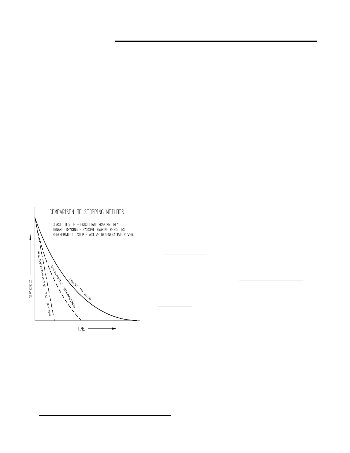
A load in motion will “coast” to a free-wheeling stop. Speed, inertia, and friction of the load determine how
long the stopping will take. The faster a load is moving, the longer
the load requires to stop. Larger inertias (more mass) take longer to
stop, but a higher friction load slows it down faster. A moving load
stops in a coasting situation by dissipating the energy of motion as
frictional heat, which acts as a brake. If inertia is high and friction is
low, the load will take a longer time to stop. We can use mechanical
brakes to increase the amount of friction.
A non-regenerative
than the load would slow down by itself. It cannot act as a brake. We
can supply braking force by making the motor act as a generator.
We can dissipate the energy of the inertia into passive resistors, but
we cannot connect the resistors until after we shut off the drive
(dynamic braking). With AC motors and brush-type DC drives, we
must keep the stationary fields energized, but not with BLDC. Even if
we lose drive power or plant power, dynamic braking still works.
Regenerative
control is active. A motor that operates on a regenerative drive
becomes a generator when it rotates at a speed faster than set
speed. The amount of power generated relates to the speed, inertia,
and friction of the load and motor. The regenerative drive accepts
the current from the motor, and dissipates the energy. The dissipative load presented by the controller must
be adequate.
When the motor generates energy, and the drive receives it, then the motor is REGENERATING. A
motor in the regenerating mode develops torque in the opposite direction of its rotation. It is not drawing power
from the supply, as it is in the motoring mode.
Regenerative power capability gives motors and controls the ability to change from higher
speeds to lower speeds quickly. This includes zero speed and the reversal of motor direction. This
happens much more quickly than with non-regenerative types of controls. The result is more rapid
stops and reversals of loads that would otherwise be a lot more sluggish in these actions.
drive can not slow down a load in less time
drives can supply braking force while the motor
OFFICIAL 6/4/2001
Page 5
Page
4
Model
1000AR Installation and Operation Manual
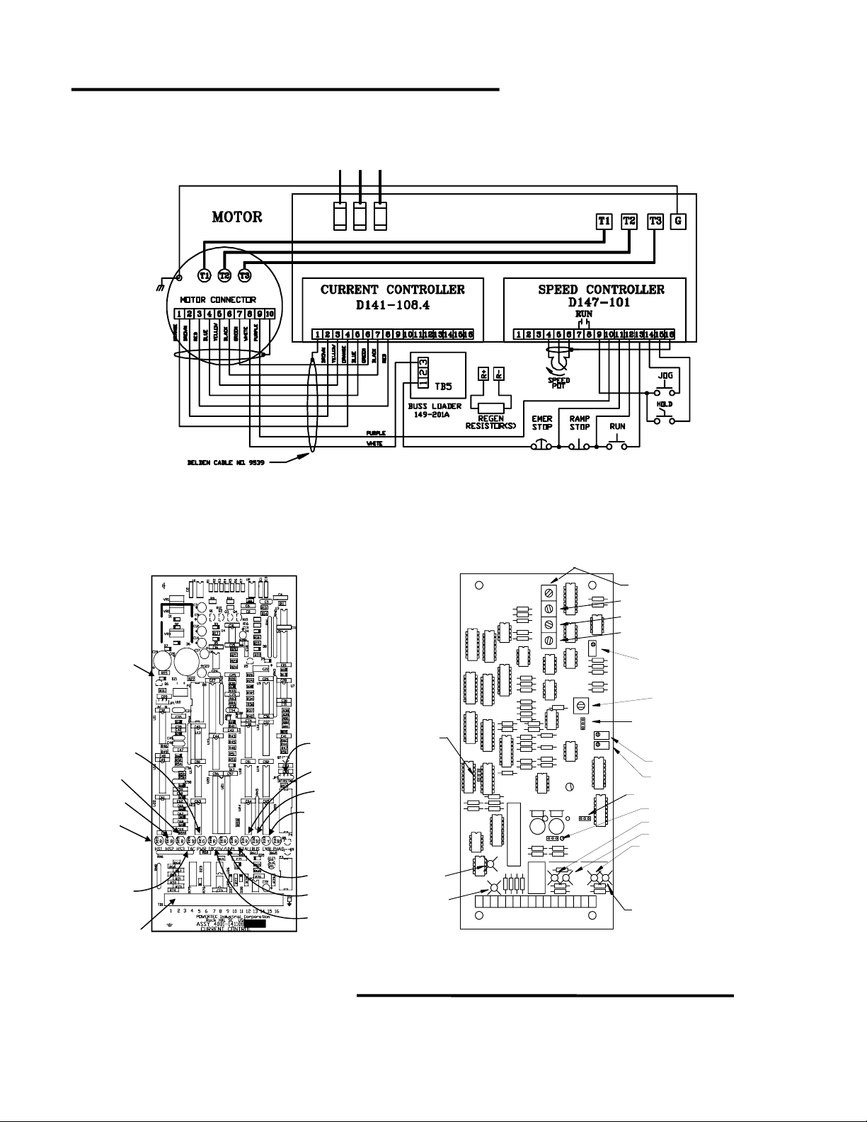
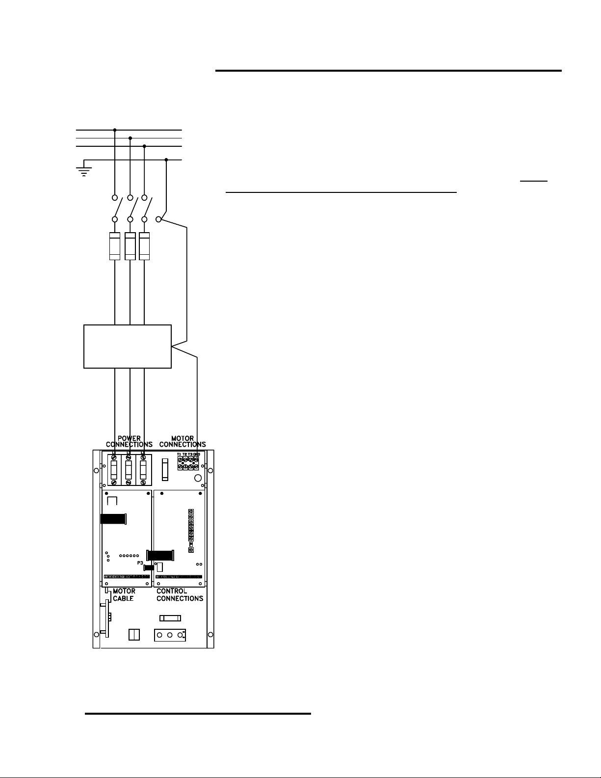
MODEL 1000AR STANDARD CONNECTIONS
Power Input
L1 L2 L3
Output Terminals
Input
fuses
Warning:
Do Not Connect
Input Power Leads
to Output Terminals
CURRENT CONTROLLER
BOARD
REGEN SPEED CONTROLLER
147-101
POWERTEC
STAB
GAIN
MCL
RCL
JP1
MAX SPD
JOG
DIR/RL
REGEN
ENABLED
DIR
SEL
P4
RUN
TB1
1 2 3 4 5 6 7 8 9 10 11 12 13 14 15 16
COAST
STOP
DECEL
ACCEL
RAMP STOP
2Q/4Q
ESTOP
RUN
JOG
HOLD
POWER
GREEN
HS3
RED
HS2
RED
HS1
RED
TAC
RED/GREEN
TB1
6/4/2001 © copyright 1997 by Powertec
JP3
STALL
RED
BUS
RED/GREEN
ENABLE
YELLOW
PL
RED
OV/UV
RED
IOC
RED
Page 6

Model
Follow these steps to quickly set up and operate the Model 1000AR Brushless DC drive. If you are not
sure of the procedure for any of the steps, consult the installation section (beginning on page 9).
1000AR
Installation and Operation Manual
UICK START
Q
CONNECTIONS
Connect the proper three-phase AC power from a suitably rated switching device to the input terminals L1, L2,
1.
and L3. Check the nameplate. The sequence of the phases is not important to the drive.
Connect the power system ground to the GND terminal. Make sure the system ground is earth ground.
2.
Connect T1 of the motor to T1 of the drive. Connect T2 to T2, and T3 to T3. The order of connection is
3.
important. The motor will not run with improper motor connections..
Connect a ground wire from the motor’s ground lug to the GND terminal on the drive.
4.
Connect the resistor to R+ and R- terminals on the chassis. If you have a separate bus loader, see page 21.
5.
Connect the encoder cable to the motor. Consult the drawing on page 4. The cable used should be a nine-
6.
conductor shielded cable. The colors do not matter, but they aid in tracing wires. Connect the shield at both
ends of the cable (the shield continues inside the motor, but is not connected there).
Connect a 10 Kilo-ohm Speed Potentiometer to TB2 terminals 4 (CW), 5 (Wiper), and 16 (CCW). Connect the
7.
shield of the speed pot cable to TB2 terminal 16. To reverse rotation connect CW to TB2 terminal 6.
TB2 terminal 10 should be connected to the motor thermal (cable). The other side of the motor thermal should
8.
be connected to TB5 terminal 3 (bus loader). Connect an Emergency Stop (ESTOP) button between TB3
terminal 1 and TB2 terminal 11. Use a normally-closed, maintained-open contact type pushbutton.
Connect a normally closed, momentary type, STOP pushbutton between TB2 terminals 11 and 12.
9.
Connect a normally open, momentary type, RUN pushbutton between TB2 terminals 12 and 13.
10.
If desired, connect a normally open, momentary type, JOG pushbutton between TB2 terminals 9 and 14.
11.
If desired, connect a normally open, momentary type, HOLD pushbutton between TB2 terminals 9 and 15.
12.
P
AGE
5
START UP
Before applying power, turn the speed pot fully counter-clockwise (CCW) and turn the MCL and RCL
1.
potentiometers fully counter-clockwise. Do not connect the motor to a load for its initial run..
When you apply power, the PWR LED should light up GREEN immediately.
2.
When you apply power, the BUS LED should light up RED immediately.
3.
When power is on, the HS1, HS2, and HS3 LED’s may or may not be on RED, depending on the position of
4.
the motor. Only one or two should light; never all three and never none.
When power is on, the TAC LED may be OFF, RED, GREEN, or ORANGE.
5.
Within 30 seconds, the BUS LED should turn GREEN and the you should hear the charging contactor click as
6.
it energizes. If this does not happen within 30 seconds, shut power off and consult the troubleshooting section.
The ESTOP LED should be ON GREEN on the Speed Controller board.
7.
Press and release the START button. The RUN LED should light GREEN. The CURRENT LIMIT LED may
8.
come on GREEN at this time because the MCL pot is all the way counter-clockwise.
Immediately after the RUN LED comes on, the ENABLE LED should light on both boards.
9.
Increase the speed pot reference to about 10% of its rotation from the CCW position.
10.
Turn the MCL pot slowly clockwise. If the motor does not turn (HS1, HS2, HS3, and TAC will start blinking)
11.
before MCL is at 50%, turn the MCL pot back down fully CCW. Consult the troubleshooting section.
Leave the MCL pot at 50 % and increase the speed pot to 50% of its rotation. Check the motor speed with a
12.
hand-held tachometer. Adjust the MAX speed pot, if necessary to attain 50% speed.
Turn the speed pot to 100% and measure the motor speed. Adjust MAX speed if necessary.
13.
Press the Normal Stop button and start again. Time the acceleration to full speed and set ACCEL time.
14.
Turn the RCL pot to 50%. Turn speed pot to 0% (CCW) and time decel ramp. Adjust DECEL for correct time.
15.
Set STAB and GAIN to 50%. Press the Normal Stop button. Both ENABLE LED’s should go OFF.
16.
Run the motor at high speed and push the HOLD button. The HOLD LED should light RED. The motor should
17.
stop. Release the button and the motor should return to the previous speed.
Press Stop. Press the JOG button. The JOG LED should light GREEN. Set the JOG speed, if desired.
18.
The motor is ready for service.
19.
OFFICIAL 6/4/2001
Page 7

Page
6
Model
1000AR Installation and Operation Manual
REFERENCE PAGES
Specifications.......................................................................................................................................... 2
Model 1000AR Standard Connections.................................................................................................... 4
Model 1000AR Dimensions Chart ........................................................................................................10
Model 1000AR AC
Model 1000AR
Regenerative Resistors .......................................................................................................................16
Contactor Specifications .....................................................................................................................18
Dynamic Braking Resistors ................................................................................................................. 18
Model 1000AR Control Connections Table .........................................................................................20
Terminal Descriptions List ...................................................................................................................22
PLC Interface Suggestions .................................................................................................................24
Digital Mode Notes ..............................................................................................................................26
Analog Versus Digital Operation Comparison .....................................................................................28
Standard Basic Connection Diagram ................................................................................................... 30
Capacitor Board Location and Layout ..................................................................................................32
Current Controller Board Layout .......................................................................................................... 34
Speed Controller Board Layout ............................................................................................................34
Jumpers List .......................................................................................................................................34
LED Indicators - Current Controller Board ........................................................................................... 36
LED Indicators - Speed Controller Board.............................................................................................. 38
Adjustments .........................................................................................................................................40
Simplified Power Schematic ................................................................................................................42
Semiconductor Diagrams......................................................................................................................42
Transistor Module Static Test ............................................................................................................... 44
Diode Bridge Test ................................................................................................................................ 46
Transistor Leakage Test ....................................................................................................................... 46
Encoder Waveforms and Connections ................................................................................................. 48
IOC Tests.............................................................................................................................................. 50
OV/UV Tests ......................................................................................................................................... 50
Block Diagram - Speed and Current Controller boards .......................................................................52
Base Driver board- Layout and Connections........................................................................................ 54
Input
Electrical Ratings Table .............................................................................. 12
Output
Electrical Ratings Table ................................................................................. 14
6/4/2001 © copyright 1997 by Powertec
Page 8

Model
1000AR
Installation and Operation Manual
ABLE OF CONTENTS
T
P
AGE
7
INTRODUCTION
..................................................................................................................................................... 1
REGENERATIVE … OPERATION
QUICK START
REFERENCE PAGES INDEX
MOTOR PROTECTION
WARRANTY
......................................................................................................................................................... 5
............................................................................................................................. 6
........................................................................................................................................ 9
............................................................................................................................................................. 9
INSTALLATION
How Do I …
Physically Install
Connect AC Power
Connect the Motor
Connect the Regenerative Resistors
Install an
Install
Connect
Get
Connect an
Connect a
Connect a
Installation Checklist
Output Contactor
Dynamic Braking
Standard Control Circuits
RUN
, Zero Speed,
DIGITAL Speed Reference
DIGIMAX
the Model 1000AR Drive ?.....................................................................................11
to the 1000AR Drive ? .......................................................................................13
to the 1000AR Drive ? ........................................................................................15
? ............................................................................................................19
? ..................................................................................................................19
FAULT
ANALOG Speed Reference
? ......................................................................................................................29
.......................................................................................................................31
, and
START UP
................................................................................................................... 3
to the Model 1000AR? .........................................................17
? ...............................................................................................21
ENABLE
?............................................................................................27
Information ? ............................................................. 23
?.........................................................................................25
What Happens When I …
Apply Power
Give the Start Command
Give the Speed Command
Slow down or Overhaul the Model 1000AR .........................................................................................39
Make an Adjustment
to the Model 1000AR Drive ? ........................................................................................33
to the Model 1000AR Drive.......................................................................35
to the Model 1000AR Drive .................................................................... 37
on the Model 1000AR Drive............................................................................. 41
TROUBLESHOOTING
Troubleshooting Chart
Troubleshooting the Model 1000AR Drive ...........................................................................................43
Troubleshooting Chart - POWER LED ................................................................................................45
Troubleshooting Chart - BUS LED.......................................................................................................47
Troubleshooting Chart - HS1, HS2, HS3, and TAC LED’s ..................................................................49
Troubleshooting Chart - RUN and ENBL LED’s ..................................................................................51
Troubleshooting Chart - TAC and ZERO SPEED LED’s ..................................................................... 53
Troubleshooting Chart - CURRENT LIMIT and PHAD LED’s ............................................................. 55
OFFICIAL 6/4/2001
Page 9

Page
8
Model
1000AR Installation and Operation Manual
6/4/2001 © copyright 1997 by Powertec
Page 10

Model
1000AR
Underwriter’s Laboratories® requires this notice for UL® listed equipment.
This Notice applies to POWERTEC Brushless DC Drive Model Number 1000AR.
Installation and Operation Manual
NSTALLATION
I
Do not use this device on a circuit capable of delivering more than
5000 RMS symmetrical Amperes at 500 VAC maximum voltage.
MOTOR PROTECTION CONSIDERATIONS
You are installing a
the motor will be protected while it is in service. These protections built into your system:
“F” Series
1.
connect this switch to the drive. Look up the method of connection in the drive manual. When the thermal
switch opens, the drive must shut off before high temperatures cause damage.
2. The Model 1000AR drive provides current limiting. This protection is adjustable from 0% to 150%
of the drive’s rated output current.
3. The Model 1000AR drive provides an over-current trip. The drive shuts off the drive if peak
currents greater than 300% of the RMS rating occur.
4. The Model 1000AR drive provides fast clearing fuses in the AC input. It does not provide an input
circuit breaker unless you chose that option at the time of purchase. If you did not purchase a circuit
breaker with the drive, you must supply a means to disconnect main power.. You must do this in order to
meet the requirements of the National Electrical Code.
GENESIS
5.
Laboratories Industrial Control Equipment Specification 508. The user is responsible for complying with
local codes and practices. If you decide that you need more protection, that protection must shut off the
drive.
GENESIS
motors have a thermal switch that opens at high winding temperatures. You must
series drives do not provide running overload protection as described in Underwriters
Series Brushless DC (BLDC) drive and motor. You must consider how
P
AGE
9
SUMMARY OF WARRANTY AND DISCLAIMER
Powertec
these units against defects in materials and workmanship for a period of two years. This period begins on
the date of original shipment from the factory.
You must notify us in writing of a defect in materials or workmanship in a warranted unit. We will,
at our sole option, repair or replace such defective parts as we deem necessary to restore the unit to
service. We will make these repairs, or replacement of parts, at the factory. Shipping charges to and from
the factory and on-site service charges are the responsibility of the user.
There is no other warranty. We do not warrant the fitness of purpose for the application intended.
This warranty does not cover accidental or intentional damage or accidental or intentional abuse. This
warranty does not cover results from defective or incorrect installation, interference with other equipment,
or any other situation over which
This warranty does not cover any other claims, including, but not limited to, special, incidental, or
consequential damages.
Powertec
efforts to compile this information. If you find mistakes of fact in this manual, please notify your distributor
Powertec
or
OFFICIAL 6/4/2001
manufactures Model 1000 Series Brushless DC (BLDC) motor controls. We warrant
Powertec
supplies this manual as a guide to the use of our products. We have used our best
at once.
has no control.
Page 11
Page
10
Model
1000AR Installation and Operation Manual
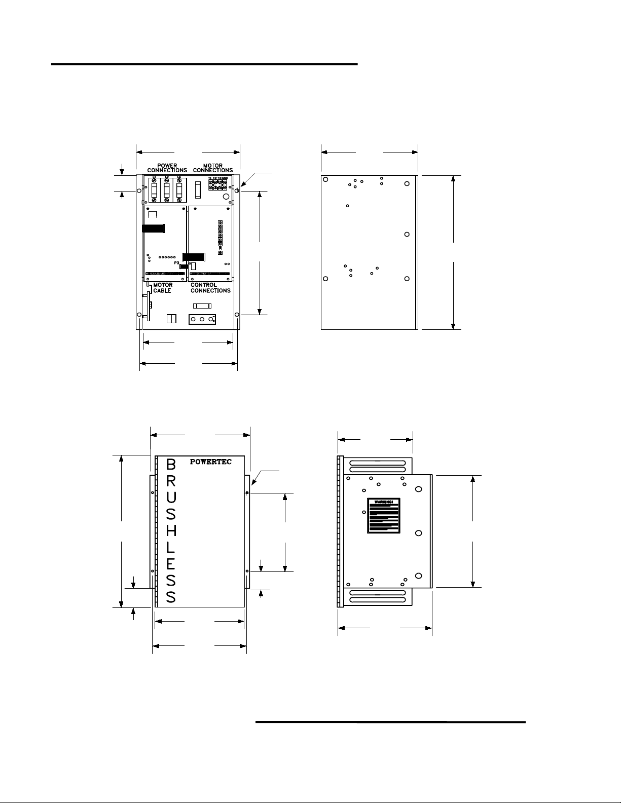
MODEL 1000AR DIMENSIONS
CHASSIS UNITS
Note: 10HP @ 230VAC, 10HP @ 380VAC, and 15HP @ 460VAC have the
same dimensions, but they have separately mounted bus loaders
2.00"
51mm
TYP
9.85"
250mm
Ø 0.28" DIA
7.1mm
TYP
4 places
9.13"
232mm
14.00"
356mm
R+ R -
8.35"
212mm
9.25"
235mm
18.00"
457mm
ENCLOSED UNITS
Note: Units with separately mounted bus loaders come in a 34”H x 24”W x 18”D Nema1 Enclosure.
22.38"
568mm
9.85"
250mm
Ø 0.28" DIA
7.1mm
TYP
4 places
14.00"
356mm
7.05"
179mm
18.00"
457mm
1000
REGEN
8.90"
2.20"
56mm
226mm
9.25"
235mm
ALL DIMENSIONS ARE APPROXIMATE. Consult factory for certified dimensions.
6/4/2001 © copyright 1997 by Powertec
2.00"
51mm
TYP
9.25"
235mm
Page 12
Model
1000AR
Installation and Operation Manual
P
AGE
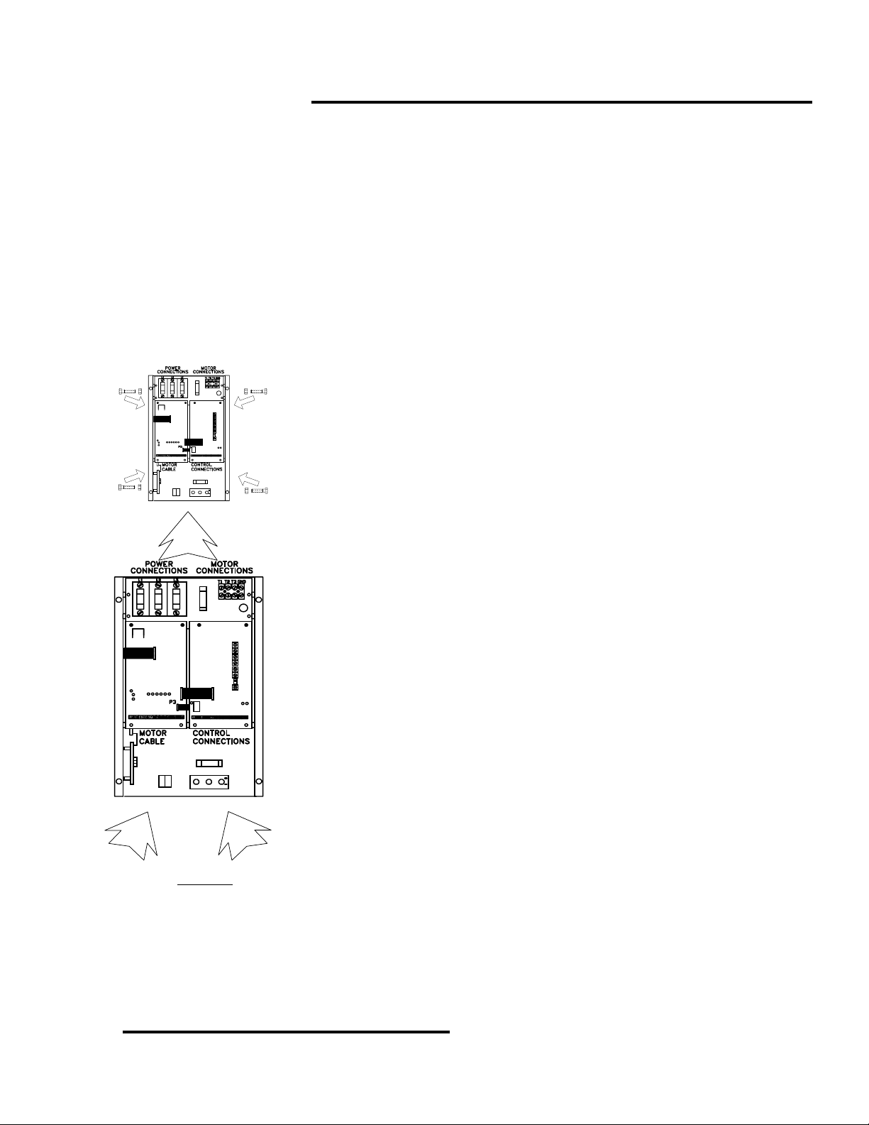
HOW DO I …
PHYSICALLY INSTALL THE MODEL 1000AR DRIVE?
Use of the Model 1000AR drive above 3300 ft (1000 meters) requires de-rating.
If the drive is to be stored, store it in its original packaging in a dry environment.
Storage temperature should be between -40°C and +65°C.
WARNING: DANGEROUS HIGH VOLTAGES ARE NORMAL IN THIS EQUIPMENT! WHEN THE AC INPUT POWER IS
REMOVED, THE CAPACITORS ARE NOT DISCHARGED AT ONCE! BE SURE INPUT POWER IS OFF
AND CAPACITORS ARE DISCHARGED BEFORE WORKING ON THE MOTOR OR THE DRIVE.
11
WARNING! :
Mount with 1/4-20 bolts
and nuts in 4 places
IF YOU TESTED THE DRIVE BEFORE INSTALLATION MAKE SURE THAT THE BUS HAS DISCHARGED.
Mount a Model 1000AR drive of the NEMA 1 style with the fuses at the top.
Free air must flow up through the fins on the back of the drive.
The temperature of the air around the drive (the ambient) must not exceed
40°C (104°F) with a relative humidity of 95% or less.
Leave at least 6 inches (150 mm) open space on all sides of a NEMA1
box. Do not mount it directly above a heat source, such as another drive. There
must be at least 18 inches (450 mm) open space between the units.
R+ R-
When you move a drive chassis, DO NOT handle the chassis by parts that
may bend or come loose. This applies to the front cover of the drive.
Mount the chassis style Model 1000AR drive in an upright position (fuses
at top) inside an enclosure to promote air flow through the heatsink.
The temperature of the air around the chassis unit may not exceed 55 °C
(131 °F). Relative humidity must be 95% or less, and non-condensing.
Avoid mounting one chassis directly above another. This will result in hot air
from the lower chassis flowing up into the upper chassis. Leave at least 12
inches (300 mm) of open space between them.
There must be free panel space of at least 3 inches (75 mm) above and
below the chassis.. This allows air flow through the heatsink fins.
The total heat dissipation within the electrical enclosure determines its size.
A list of heat outputs of the Model 1000AR is in the table on page 6.
NEMA1 and NEMA12 ventilated boxes depend on air flowing through the
enclosure for cooling. They must have an air flow of 1 CFM (cubic feet per
minute) per 10 watts of dissipation (1 cu meter / min per 350 watts).
R
R-
+
The allowance for totally enclosed units is 1 square foot of enclosure surface
per 7 watts of dissipation (75 watts per square meter). Surface area includes
front, sides, top and bottom surfaces. Enclosure surfaces not exposed to cooling
air do not count.
For further information, consult the publication
THERMAL MANAGEMENT
,
available from your distributor.
If a separate
bus loader has been supplied, mount it on the panel near the drive. Mount it with the fins
vertically oriented, and make sure that air can flow through its heatsink.
Bus Loader Resistors
become VERY HOT in the performance of their duty. Bus loader resistors
must be mounted OUTSIDE THE ENCLOSURE in a dry, well ventilated area, where there are no
flammable materials. Bus loader resistors are supplied in an expanded metal cage for wall mounting.
MODEL 1000AR AC INPUT ELECTRICAL RATINGS
OFFICIAL 6/4/2001
Page 13

Page
12
NOMINAL
AC LINE
VOLTAGE
Model
1000AR Installation and Operation Manual
HORSEPOWER
KILO-
WATTS
MAXIMUM
CONTINUOUS
CURRENT
AC LINE
INPUT
KVA
MAXIMUM
HEAT
OUTPUT IN
WATTS
230 ½ 0.37 1.4 0.550 35
230 ¾ 0.56 1.8 0.725 42
230 1 0.75 2.4 0.950 60
230 1.5 1.1 3.6 1.450 85
230 2 1.5 4.9 1.950 122
230 3 2.2 7.3 2.900 165
230 5 3.7 12.1 4.825 232
230 7.5 5.6 18.1 7.200 281
‡
230 10 7.5 23.9 9.525 385
380 1 0.75 1.5 0.975 36
380 1.5 1.1 2.2 1.450 55
380 2 1.5 2.9 1.925 70
380 3 2.2 4.4 2.875 105
380 5 3.7 7.3 4.810 142
380 7.5 5.6 10.9 7.150 178
‡
380 10 7.5 14.1 9.250 222
460 2 1.5 2.4 1.910 113
460 3 2.2 3.5 2.800 144
460 5 3.7 5.9 4.750 200
460 7.5 5.6 8.9 7.100 258
460 10 7.5 11.4 9.050 355
‡
460 15 11 17.8 14.150 475
Indicates drives supplied with separate bus loader.
‡
Notes
The Model 1000AR drives will operate on power line frequencies from 48 to 62 hertz.
The
capable of supporting the starting current of AC motors without dropping more than 10%. Brief power line disturbances
may trip a drive supplied with less than 95% of the nominal line voltage.
source. Measure the actual input line voltage while the control is operating the motor in a loaded condition.
generate significant noise back onto the power service. Events that distort the AC waveform may lower the bus voltage.
These may trigger an under-voltage or power loss condition.
treacherous problem that is capable of causing destructive results. It can also cause intermittent and annoying problems.
The methods used in the installation of the equipment plays a large part in prevention of electrical noise problems in
operation. Any digital type control requires that extra care be taken in installation. Pay attention to the grounding of the
equipment, the shielding of wires and cables, and the placement of wires in the conduit runs. Pay attention to the
sections of this manual that address the precautions against noise. This also applies to peripheral equipment.
protection. Pay particular attention to power and grounding requirements.
tolerance
Do not measure the input voltage while the drive is not running. This neglects the effects of load on the power
Brief power line disturbances will not normally disturb the Model 1000AR drives. The Model 1000AR drives do not
One of the most frequent problems encountered with digital type equipment is electrical noise. Noise is a
When you use other manufacturer’s equipment in a system, follow their directions regarding noise suppression and
of the input voltage is +10% to -10% of the voltage listed on the nameplate. A service must be
6/4/2001 © copyright 1997 by Powertec
Page 14
HOW DO I …
.
TRANSFORMER
R+ R-
Model
1000AR
Installation and Operation Manual
CONNECT AC POWER TO THE 1000AR DRIVE?
Standard Model 1000AR Brushless DC drives will not operate on
single phase AC power.
Model 1000AR drives require a three-phase main power source with
KVA rating
a
is NOT returned to the power line during regeneration.
The branch service rating (in KVA) supplying the drive must not be
more than 10 times the HP rating of the drive. If it is, you may need
special disconnecting means with a higher AC short-circuit current
interrupting capacity.
Model 1000AR drives do not include a disconnecting switch for input
power. The user must supply a switch that meets the applicable code
requirements.
The maximum Interrupting Capacity (AIC) of the fuses is 5,000
amperes. You will need a switch with a rating greater than 5,000 amperes
if the short circuit current on the service is greater.
You do not
operation of the drive. You may want to use one, or you might need to
meet local code requirements. You need to change the voltage level.
In those cases, you will need a transformer with a KVA rating at least
as large as the HP rating of the drive. If you use a transformer, we
recommend a delta/wye winding configuration. We also recommend that
the transformer have taps to raise or lower voltage.
The user protection supplied before the wires determines the sizes of
the power wires to the drive input. The table on the opposite page lists the
full load AC line currents of Model 1000AR drives.
The order of connection of the input phases is not important.
We size the main fuses to protect the semiconductor elements of the
unit. THEY MAY OR MAY NOT MEET THE REQUIREMENTS OF
NATIONAL, STATE AND/OR LOCAL ELECTRICAL CODES. The
responsibility for meeting the branch service protection and other code
requirements and safety codes belongs to the user.
NOTICE: AC LINE CURRENT OF THE BLDC DRIVE IS NOT
The AC input current is directly proportional to the POWER output of
the motor. The only time the AC line current reaches its full value is when
the motor is operating at full speed with full load.
BY MEASURING AC INPUT LINE CURRENT TO THE BLDC MOTOR
at least equal to the
necessarily
REPRESENTATIVE OF MOTOR LOAD CURRENT!
DO NOT ATTEMPT TO MEASURE MOTOR LOAD
CONTROL.
HorsePower rating
need an ISOLATION TRANSFORMER for
of the drive. Power
P
AGE
13
OFFICIAL 6/4/2001
Page 15
Page
14
Model
1000AR Installation and Operation Manual
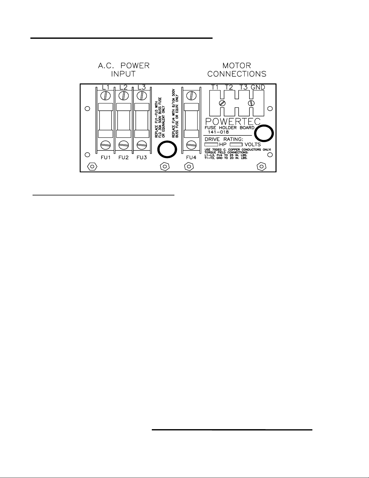
MODEL 1000AR FUSE BOARD
Model 1000AR Output Electrical Ratings
NOMINAL
AC LINE
VOLTAGE
230 ½ 0.37 2.2 3.3 68.1 K
230 ¾ 0.56 3.4 5.1 45.3 K
230 1 0.75 4.7 7.0 33.2 K
230 1.5 1.1 7.0 10.5 22.1 K
230 2 1.5 8.5 12.7 18.2 K
230 3 2.2 12.8 19.2 12.1 K
230 5 3.7 22.8 34.2 6.81 K
230 7.5 5.6 31.1 46.6 4.99 K
‡
380 1 0.75 2.7 4.0 56.2 K
380 1.5 1.1 3.9 5.8 39.2 K
380 2 1.5 4.7 7.0 33.2 K
380 3 2.2 7.8 11.7 20.0 K
380 5 3.7 14.1 21.1 11.0 K
380 7.5 5.6 18.8 28.2 8.25 K
‡
460 2 1.5 4.0 6.0 39.2 K
460 3 2.2 6.9 10.3 22.1 K
460 5 3.7 11.6 17.4 13.3 K
460 7.5 5.6 17.1 25.6 9.09 K
460 10 7.5 20.7 31.0 7.50 K
‡
230 10 7.5 41.5 61.1 3.74 K
380 10 7.5 25.0 37.5 6.19 K
460 15 11 31.1 46.6 4.99 K
Indicates 1000A models.
‡
HORSEPOWER
KILO-
WATTS
MAXIMUM
CONTINUOUS
MOTOR
CURRENT
MAXIMUM
MOMENTARY
MOTOR
CURRENT
NOMINAL
HP
CALIBRATE
RESISTOR
6/4/2001 © copyright 1997 by Powertec
Page 16
Model
1000AR
Installation and Operation Manual
P
AGE
HOW DO I …
CONNECT THE MOTOR TO THE 1000AR DRIVE?
We ship every drive from the factory with A STANDARD CONNECTIONS card.
Connect the motor lead marked T1 to the
T1 terminal on the drive. Connect the T2 lead
to T2 on the drive, and connect T3 to T3. Other
connections to T1, T2, and T3 at the motor will
vary with the motor. The motor will not operate
if the power wires from motor to drive are not in
the proper order.
Full load motor current determines the wire
size to the motor. The table on the opposite
page lists these currents.
R+ R-
T1 T2 T3
TB1
1 2 3 4 5 6 7 89
TB2
16
1 2 3 4 5 6 7 89
Orange
Brown
Blue
Yellow
Red
Black
Green
Purple
White
18
MOTOR
1 2 3 4 5 6 7 8 9 S
BLDC
GND
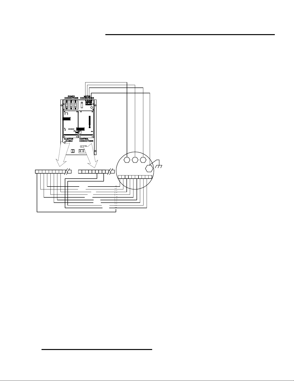
ADDITION TO GROUNDING THE MOTOR FRAME TO ITS MOUNTING, WHICH IS REQUIRED BY
CODE.
The purpose of this separate ground is to equalize the potential between the motor's frame and the
drive chassis. There may be enough impedance to broadcast EMI and RFI even with the motor grounded
to its mounting frame. A direct wire connection between the motor frame and the drive chassis minimizes
interference in other equipment.
The encoder feedback cable must be a shielded cable. Connect the shield to TB1 terminal 1 on the
control end. Standard installation requires a nine-conductor shielded cable (Belden
equivalent). The colors of this cable correspond to the colors of the wires in the motor and on the
connection diagram. You may interchange the Purple and White wires without ill effect.
The shield must be continuous from the motor to the control. Do NOT ground the shield at
intermediate points. This applies to all junction boxes installed between motor and control.
Any high voltage, high frequency
equipment generates EMI and RFI.
MUST USE METALLIC CONDUIT TO
ENCLOSE MOTOR WIRES BETWEEN THE
MOTOR AND THE DRIVE.
This will minimize
interference.
You must install a ground wire between the
motor frame and the drive chassis. There is a
ground lug in most motors. If there is no
ground lug, make a connection at any bolt in
the motor junction box.
THIS GROUND WIRE MUST BE RUN IN
™
part #9539 or
YOU
15
DO NOT USE THE SHIELD OF THE ENCODER CABLE AS AN ACTIVE CONDUCTOR!
If you want to use the motor thermal protector in a 120 VAC circuit, run it in wiring separate from the
cable. Use seven-conductor shielded cable. In this case, if the cable wire colors are different from the
diagram, you need to check them carefully for proper connections.
OFFICIAL 6/4/2001
Page 17

Page
16
Model
1000AR Installation and Operation Manual
REGENERATIVE RESISTORS
Regenerative motor controllers require a method of handling energy that is generated by the motor
and returned to the drive. Traditionally, this has been handled by two methods: (1) using the power lines
as a power sink by dumping excess energy back into the power source, and (2) dissipation as heat.
The first method was popular with DC drives, but it is becoming very unpopular because of the
disruptive effect of the electrical noise in the power system.
The first method has been used by Brushless DC drives, inverters, and vector-type controls. In motor
systems at larger horsepowers, the dissipation means can get bulky and expensive. At horsepowers in the
range of the 1000AR series of drives, they are not a big problem.
Regenerative resistors are rated in terms of resistance and power.
The resistance of the bus loader resistors must allow enough current to flow from the bus through the
resistor(s) to remove the energy at a rate faster than the motor can generate it. The bus voltage times the
bus loader current must be greater than 150% of the motor’s full power rating.
The power rating of the resistors depends on the duty cycle of the regeneration.
ratings for the GENESIS series of drives:
1. STOPPING DUTY = used to stop the motor once per minute = approximately 10% duty cycle.
2. EXTENDED DUTY = used to stop high inertia loads = approximately 25% duty cycle.
3. LIFTING DUTY = used on cranes and hoists and inclined conveyors = 50% duty cycle.
4. CONTINUOUS DUTY = 100% duty cycle.
The standard supplied with standard GENESIS drives is STOPPING DUTY.
Any duty cycle other than stopping duty MUST BE EVALUATED BY A MECHANICAL ENGINEER.
The amount of regenerative power needed is a MECHANICAL, not an ELECTRICAL, calculation.
To avoid using many different resistors, standard resistor values have been adopted.
The standard resistor for 230 VAC drives is 25 ohms @ 420 W.
The standard resistor for 460 VAC drives is 70 ohms @ 420 W.
The standard resistor for 380 VAC drives is also 70 ohms @ 420 W.
One resistor is used in parallel for each 5 HP or portion thereof.
BUS LOADER RESISTOR TABLE - Standard Duty Resistors
Line Voltage Motor HP Resistors Equivalent R Dissipation Peak Amps Ave. Amps
HP # @ ohms ohms watts ADC ADC
VAC
230 up to 5 1 @ 25 25.00 375 15.00 1.00
230 7.5 2 @ 25 12.50 750 30.00 1.50
230 10 2 @ 25 12.50 750 30.00 2.00
380 up to 5 1 @ 70 70.00 375 8.86 0.60
380 7.5 2 @ 70 35.00 750 17.72 0.90
380 10 2 @ 70 35.00 750 17.72 1.20
460 up to 5 1 @ 70 70.00 375 10.72 0.50
460 7.5 2 @ 70 35.00 750 21.45 0.75
460 10 2 @ 70 35.00 750 21.45 1.00
460 15 3 @ 70 23.33 1125 32.16 1.50
All resistors are connected in parallel.
Powertec
uses four
6/4/2001 © copyright 1997 by Powertec
Page 18
Model
1000AR
Installation and Operation Manual
P
AGE
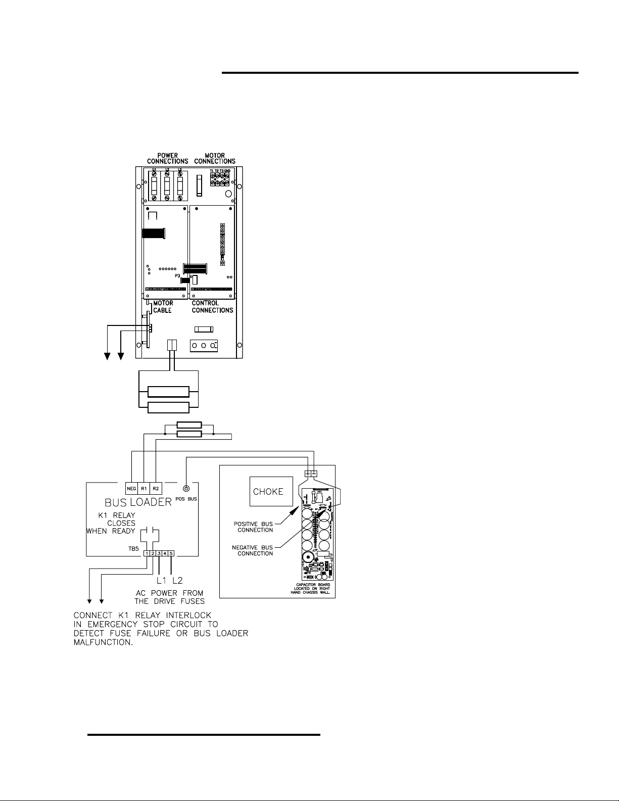
HOW DO I …
CONNECT THE REGENERATIVE RESISTORS TO THE MODEL
1000AR?
All but the largest Model 1000AR drives have the bus
loader (149-201)built into the chassis. The bus loader mounts
on the lower left-hand side panel and it plugs directly to the
driver board. The power components for the bus loader are on
the lower third of the chassis.
You must include the interlock between terminals TB5-1
and TB5-3 in the control circuits. You must locate the drive’s
regenerative resistors outside the enclosure in a clean, dry,
well-ventilated area.
You MUST connect the regenerative resistors. The
horsepower of the drive, the inertia of the load, and the duty
cycle for regeneration determines the number of resistors
We use a standard 10% duty cycle for stopping duty and
for light regenerative loads. The standard resistor package is
NOT guaranteed to handle all situations. IT IS THE
R+ R-
CONTROL
CIRCUIT
INTERLOCK
Operating the 1000AR drive without the Bus Loader attached, or with the Bus Loader disabled, will
result in the drive tripping. OverVoltage will occur as soon as regenerative operation is attempted. This
could also result in damage to the drive.
BUS LOADER
RESISTOR(S)
RESPONSIBILITY OF THE USER TO SPECIFY THE SIZE OF
THE REGENERATIVE RESISTOR PACKAGE. If necessary,
an engineering evaluation should be made.
The interlock is built into the Bus Loader board. The
interlock will open if the bus loader fuse opens up or if the
board fails to function. If the drive tries to regenerate without
the bus loader operating, the drive will trip.
The separately mounted bus loader (149-
101) should be mounted close to the drive. The
resistors must be mounted in their own cage
outside any enclosure. Mount the resistors in a
clean, dry and well ventilated area away from
personnel.
TB5 terminals 3 and 5 must be connected
to the AC drive power. The drawing shows L1
and L2 connected, but any two of the three
phases can be connected.
The resistors must be connected to the R1
and R2 terminals. All standard resistors are
connected in parallel (see page 10 for resistor
values).
Connect the interlock at TB5 terminals 1
and 2 into the control circuit (see page 15).
Connect the fuse input to the POS BUS
connection on the Capacitor Board. Connect
the NEG terminal to the NEG BUS connection
on the Capacitor Board.
17
OFFICIAL 6/4/2001
Page 19

Page
18
Model
1000AR Installation and Operation Manual
CONTACTOR SPECIFICATIONS
If you want to operate an Output or DB Contactor directly
1.77"
13 21 31 41
A1
from the Model 1000AR, you must choose a coil that draws
less than 50 milliamps DC.
The Output Contactor drawing on page 11 shows the
connections for direct operation of the contactor (use the
same connections for Dynamic Braking). The coil must be
48VDC and draw less than 50 ma DC (2.4 Watts). This is the
1.66"
most power available from the Model 1000AR drive’s supplies.
To use a 115VAC or 230 VAC coil, you need a 156-012
Contactor Control board, as shown in the drawing on page 11.
Use the same drawing for the Output Contactor. Maximum
14 22 32 42 A2
TOP VIEW
0.19"
current for the Contactor Control board is 1 Amp at 230 VAC.
You need three normally open power poles and a normally
open auxiliary for an Output Contactor. The contactor does
not make or break with current in the power contacts. Choose
the contact ratings only on the basis of carrying the current.
For Dynamic Braking, you need three normally closed
power poles and a normally open auxiliary. The contacts make
with current present, but they do not break current in the
dynamic braking operation. Choose contacts accordingly.
1.54"
1.25"
The contactor outline sketched at left is from the SH-04
series by AEG Industries. The model used for the Output
Contactor is part number SH-04.40 and the Dynamic Braking
is SH-04.13. Contact ratings are 16 Amps.
BOTTOM VIEW
DYNAMIC BRAKING RESISTORS
We choose DB resistors for their ability to absorb high inrush currents and to accept large amounts of
power for short periods of time. Typical DB resistors can absorb ten times their power rating for up to five
seconds. The resistors must then cool down to ambient temperature before they can dissipate their full
rating again (usually a few minutes). It is possible to extend the ratings by about three times with power
resistors by forced-air cooling.
You can derive an approximate value of dynamic braking resistor from the bus voltage and the full
load current on the nameplate of the motor:
Bus Voltage X 0.47
Each Resistor Value ~ ---------------------------------- Motor FLA
Three resistors (or groups of resistors) are necessary. The power rating of each should be:
Power > 0.02 X (Buss Voltage)
These formulas are very general, and results will vary from motor to motor. For dynamic braking
tailored to your application, consult
POWERTEC
Engineering.
2
/ (Resistor Value)
6/4/2001 © copyright 1997 by Powertec
Page 20

HOW DO I …
R+ R-
TB2
8
9 10 11 12 13 14
7
CONTACTOR
3 POLE N.O.
1 N.O. aux
48VDC COIL
@ 2.4 W
M
Bus Loader
Interlock
M (aux)
J
EMER
STOP
Model
1000AR
Installation and Operation Manual
CONNECT AN OUTPUT CONTACTOR?
T3
T2
T1
GND
M
T1T2T3
G
BLDC
MOTOR
MOTOR
THERMAL
STOP
15 16
RUN
J
JOG
DO NOT BREAK THE GROUND CONNECTION OR THE CABLE
CONNECTIONS WITH THE OUTPUT CONTACTOR.
You may use an output contactor with the Model 1000AR.
You MUST interlock the contactor with the Emergency Stop. You
WILL damage the drive if you do not interlock the contactor.
Requirements for the Model 1000 series are:
1. The contactor must close its main power contacts
BEFORE it enables the drive;
2. The contactor may only open its contacts AFTER
disabling the drive.
The contactor does not make or break current.
The figure at left shows the connections for a 48VDC output
contactor (such as AEG part number SH-04.40-ODC, which is
available from
POWERTEC
).
In this configuration, the contactor pulls in on a run
command and drops out ONLY on an emergency stop. The
contactor stays energized during normal stops.
POWERTEC
makes an optional track mount PC board (Part
# 156-012) for sequencing of contactors with AC coils.
P
AGE
19
HOW DO I …
6
CONNECT DYNAMIC BRAKING?
TO MOTOR
THERMAL
Bus
Loader
Interlock
CONTACTOR
3 POLE n.c.
1 N.O. Aux
COIL < 230VAC
You MUST interlock the contactor with the
Emergency Stop when using Dynamic Braking. You will
damage the drive and/or the resistor banks if you do not
properly interlock the contactor.
The requirements are:
1. The contactor must open the main power
contacts BEFORE the drive is enabled; AND
2. The contactor may only close its contacts
AFTER disabling the drive.
The AEG SH-04.13-ODC contactor is suitable to
the circuitry above. The figure on the left shows how to
use a POWERTEC 156-012 Contactor Control board to
control a larger contactor or a contactor with an AC coil.
In this configuration, the contactor energizes on a
run command and drops out ONLY on an emergency
stop. The contactor stays energized on a normal stop.
OFFICIAL 6/4/2001
Page 21

Page
20
Model
1000AR Installation and Operation Manual
MODEL 1000AR CONTROL CONNECTIONS
Normally closed thermal switch in the motor. THE MOTOR
THERMAL SWICH MUST BE USED TO PROPERLY PROTECT
THE MOTOR! When the switch opens, the drive must be shut
off to prevent damage to the motor from overheating.
Voltage must be present to RUN or JOG. When removed,
ENABLE REQUEST is blocked immediately (see page 29) and
all control functions are disabled. Do not connect voltage to
terminal with permanent jumper. In RAMP STOP mode, this is
the only way to stop the drive.
Voltage must be present to maintain RUN mode after a
momentary START is removed. When voltage is removed, the
drive decelerates to zero speed at the DECEL rate and shuts
off if RAMP STOP jumper JP2 is installed. Otherwise drive
shuts off immediately and the motor coasts to a stop.
Voltage must be applied to initiate RUN mode. When it is
removed, drive shuts off unless +24VDC is present at TB2-5.
RUN LED turns on when +24VDC is applied to TB2-4. RUN
LED turns off and RUN relay drops out when voltage is
removed from both TB2-4 and TB2-5.
Normally open dry contact closes when START is energized
and opens when RUN relay drops out. The RUN contact does
not open on a FAULT. The RUN contact does not close on
JOG and opens in RAMP STOP mode.
Open collector transistor output referenced to TB2-12. Rated
at 50 mADC @ 50 VDC max. This output operates only in RUN,
JOG, or RAMP STOP modes. The ZERO SPEED output turns
on at about 10 RPM and off at about 5 RPM. The ZERO
SPEED output shuts off if the ENABLE LED shuts off.
Voltage must be applied to initiate JOG mode. JOG mode will
be maintained only as long as the voltage is present. When
the voltage is removed, the drive will go to RAMP STOP mode
if COAST TO STOP jumper JP2 is installed. Otherwise the
drive shuts off and the motor coasts to a stop.
When the voltage is applied, the output of the Voltage
Controlled Oscillator is reduced to zero PPR. This causes the
drive to decelerate to zero speed in current limit and hold
there. When the voltage is removed, the drive accelerates
back to set speed in current limit.
function.
function. function.
Optically coupled transistor output (isolated). Rated at 50
mADC @ 50 VDC. Turns on when bus has achieved proper
level. Output is off when any trip occurs.
Apply voltage to switch to DIGITAL mode. TB1-10 and TB1-9
are electrically isolated from the board power supplies. The
negative side of the +24VDC used for the input must be
connected to TB1-9. External frequency must be applied to
terminal 11. Terminal 9 is also common for this frequency.
MOTOR
THERMAL
EMERGENCY
STOP
RAMP STOP
START /
RUN
RUN
CONTACT
ZERO
SPEED
JOG
HOLD
FAULT
OUTPUT
ANALOG/
DIGITAL
SWITCH
** Note: TB5 is on the Bus Loader. The Small Bus Loader interlock is TB5-1 and TB5-3.
STD: CONNECT
FROM
TB2-10 TO TB5-1**
+24VDC ON TB2-11
STD: N/C PB FROM
TB2-11 TO TB5-3**
+24VDC ON TB2-12
STD: N/C PB FROM
TB2-11 TO TB2-12
+24VDC ON TB2-13
STD: N/O PB FROM
TB2-12 TO TB2-13
TB2-7 AND TB2-8
OUTPUT: TB2-1
COMMON: TB2-16
-24VDC ON TB2-14
STD: N/O PB FROM
TB2-9 TO TB2-14
-24VDC ON TB2-15
STD: N/O PB FROM
TB2-9 TO TB2-15
NOTICE: The drive is NOT OFF in the HOLD
NOTICE: The drive is NOT OFF in the HOLD function.
NOTICE: The drive is NOT OFF in the HOLDNOTICE: The drive is NOT OFF in the HOLD
OUTPUT
COLLECTOR: TB1-12
EMITTER: TB1-13
+24VDC ON TB1-10
REFERENCE TB1-9
TB1-9 IS NOT DRIVE
COMMON
The large Bus Loader interlock is TB5-1 and TB5-2.
6/4/2001 © copyright 1997 by Powertec
Page 22

Model
1000AR
Installation and Operation Manual
P
AGE
HOW DO I …
CONNECT STANDARD CONTROL CIRCUITS?
If you are using an output contactor or dynamic
braking, go to page 19.
The table on the opposite page lists the functions of
the Model 1000AR. The table lists the connections and
descriptions of the control circuits. Read the descriptions of
the operations of these circuits very carefully. There are
differences between analog and digital modes.
The control circuits of Model 1000AR motor control
operate on 48 VDC. This results from using the positive and
negative 24 VDC supplies. Using 48VDC helps balance the
load of relays and other devices on the power supplies.
R+ R-
TB2
7
321
EMER
STOP
RAMP
STOP
START
JOG
1615141312111098
RUN HOLD
TO
MOTOR
THERMAL
Bus Loader
Interlock
TB5
Install ESTOP buttons Do NOT place a jumper across the Emergency Stop terminals. Because the
drive has a ramp to stop capability, this could set up an
RECOMMENDED THAT AN EMERGENCY STOP BUTTON (or an ESTOP relay) BE CONNECTED TO
THE DRIVE! This should be of the MAINTAINED CONTACT TYPE.
The maximum current from each of the raw supplies is
50 milliamps. Due to this limitation, you must use an
external supply when you use several external relays.
THE POWER SUPPLIES OF THE MODEL 1000AR
SHOULD NOT BE USED FOR EXTERNAL EQUIPMENT!
Powertec
has an optional power supply (part # 127-101)
available for 24VDC to power external circuits.
It is possible to operate control circuits with a variety of
devices. Standard operator devices are O.K.., but the
current flow to these devices is very small. When locating
pushbuttons more than 30 feet away from the motor control,
consider using 120 VAC control circuits.
UNSAFE
situation. IT IS STRONGLY
21
The motor thermal must be used to PROPERLY protect the motor!
You can use a "two-wire" control by connecting a contact or switch between terminals 11 and 13 on
TB2. Leave off the RAMP STOP and START buttons. This DOES NOT disable the RAMP STOP function.
The only way to disable the RAMP STOP function is removing the RAMP STOP jumper.
The RAMP STOP function in the analog mode shorts the analog reference input to zero. This causes
the motor to decelerate to zero speed before shut-down.
Note that the JOG function is disabled by the RUN function. If you activate the JOG input while the
RUN mode is in operation, there will be no effect.
The HOLD function zeroes the speed reference to bring the motor to a stop and holds the drive at
zero speed. THE DRIVE IS NOT OFF IN THE HOLD MODE! There is a potential for the motor to run
, so
the appropriate safety precautions should be taken.
OFFICIAL 6/4/2001
Page 23

Page
22
Model
1000AR Installation and Operation Manual
TERMINAL DESCRIPTIONS - MODEL 1000AR
TB1 Current Controller Board (141-108)
1 Dedicated Shields and Ground connection
2 HS1 position encoder
3 HS3 position encoder
4 HS2 position encoder
5 HS4 speed encoder
6 HS5 speed encoder
7 Encoder Common for encoder ONLY
8 Encoder +5 VDC for encoder ONLY
9 Isolated Common for terminals 10 and 11
10 Auto/Manual Selection +24 VDC for Digital Mode
11 External Frequency Input +24 VDC Square Wave
12 Collector of FAULT transistor
13 Emitter of FAULT transistor
14 Drive Load output -2VDC = 150%
15 Auxiliary Supply output +15VDC for extra encoder
16 Power Supplies Common
TB2 Speed Controller Board (147-101)
1 ON at zero speed (open collector) 30VDC 50 mA maximums
2 ON when enabled (open collector) 30VDC 50 mA maximums
3 Speed Output (open collector) 30VDC 50 mA maximums
4 -10VDC Reference Source 5 mA maximum
5 Speed Reference Input -10VDC to +10VDC
6 +10VDC Reference Source 5 mA maximum
7 RUN output contact N/O 125VAC
8 RUN output contact N/O 1A Resistive
9 -24VDC supply 50 mA maximum
10 +24VDC supply 50 mA maximum
11 EMERGENCY STOP Input +24VDC to activate
12 RAMP STOP Input +24VDC to activate
13 RUN/START Input +24VDC to activate
14 JOG Input -24VDC to activate
15 HOLD Input -24VDC to activate
16 Signal Common
TB3 Capacitor Board (141-106)
1 Horsepower calibration resistor
2 No connection
3 Horsepower calibration resistor
TB5 Bus Loader (Integral unit connected to Driver board)
1 Bus loader Interlock N/O 125VAC
2 No connection
3 Bus loader Interlock N/O 1A Resistive
HOW DO I …
GET RUN, ZERO SPEED, FAULT AND ENABLE INFORMATION?
6/4/2001 © copyright 1997 by Powertec
Page 24

TB1
ZERO
SPEED
RELAY
24VDC Coil
TB2
R+ R-
R+ R-
FAULT
OUTPUT
ISOLATOR
ENABLE
FAULT
48VDC Coil
16151413121110987
24V
DC
48V
DC
RUN
RELAY
ENABLE
TB2
Model
16151413121110987654321
-24VDC
9321
1000AR
Installation and Operation Manual
P
AGE
The RUN relay contact at TB2 terminals 7 and 8 is a dry contact
rated at 1 Amp (Resistive load) at 125VAC. You may use it in an
external circuit as long as the voltage does not exceed 125 VAC
(limitation of the terminal strip).
You may use an auxiliary relay if you need more power, or if you
need more contacts, as shown in the drawing at the left. You should
use a 48VDC coil (highly recommended) since this reduces the burden
on one supply. The diode is a general purpose type rated for at least 1
Amp at 100VDC PIV (1N4002 or equivalent).
The ZERO SPEED output at TB2 terminal 1 is an open collector
NPN transistor, rated at 50 ma at 50 VDC. The ZERO SPEED
transistor turns on at about 10 RPM and turns off at about 5.RPM
The transistor emitter is at drive common and it may interface
directly with a PLC as a sinking input.
The output can operate a relay as shown in the top drawing on
the left. The transistor returns to drive common, so it is not possible to
use a 48VDC relay with the drive’s supplies. If you use a 24VDC relay,
the current must be as low as possible. The diode is a general
purpose type.
The ZERO SPEED relay will chatter at very low speeds. You can
overcome this with a latching circuit that releases at the first dropout of
the zero speed relay.
The FAULT output at TB1 terminals 12 and 13 is the output
transistor of an optical coupler. The coupler’s rating is 100VDC @ 50
ma.
Connect a FAULT relay with a 48VDC coil as shown in the
bottom figure at left. The external FAULT relay energizes when the
drive completes power-up and de-energizes when a fault occurs.
The diode is a general purpose diode.
The Model 1000AR has an ENABLE output terminal at TB2
terminal 2. The ENABLE output is an open collector transistor that
turns on when the drive is ready to accept a reference for speed
input, whether in RUN or in JOG. You must use a 24VDC coil on the
ENABLE output.
The ENABLE output shuts off if there is a trip or when the drive
shuts off either on Emergency Stop or a non-ramp stop, or when the
+24VDC
JOG input is released.
116 654 87 10
The internal RUN relay drops out on RAMP STOP. The
ENABLE output remains energized throughout the RAMP STOP
sequence. Use ENABLE for functions which must continue when the
motor is running.
23
OFFICIAL 6/4/2001
Page 25

Page
24
Model
1000AR Installation and Operation Manual
PLC INTERFACE
SINKING CONNECTION
DRIVE
+24VDC
TB2
10
PLC
INPUT
MODULE
+V
The interface of the Models 1000 and 1000A with a
process controller is dependent upon the ability of the PC
to handle the required signals.
Most of the signals are +24 VDC or 48 VDC (positive
and negative 24 VDC supplies for control), or +10 VDC for
speed. You may also use computer generated frequency
signals for speed in the DIGITAL mode.
ZERO
SPEED
1
INPUT
There are two types of input modules.
A "sinking" connection uses the Programmable
16
COM
Controller’s own power, or an external source, and
connects it (sinks it) to common level by the connected
input device. The drawing on the left illustrates the method
for using an open collector output to "sink" the input of a
SOURCING CONNECTION
+24 VDC PC input module using an external supply from
the drive.. When the transistor turns on, it turns on the
DRIVE
ZERO
SPEED
+24VDC
TB2
10
2Kohm
MIN
1
PLC
INPUT
MODULE
+V
INPUT
input module.
A “sourcing” connection turns on the PLC module by
supplying power to it. The second figure shows a sourcing
connection. Notice, however, the inverted sense, that is,
when the transistor turns on, the input is not.
You can use the fault output with connections similar
to those in the above figures. You can use a PLC input
module, with the FAULT output of the control at TB1
16
COM
terminals 12 and 13, to sense a FAULT in the drive. The
bottom figure illustrates this.
FAULT MONITOR
PLC
INPUT
MODULE
+V
You need to keep in mind that the FAULT isolated
output transistor is "ON" when there is no fault present.
You should accomplish all of the programmable
controller operations of the standard control circuits of the
Models 1000 series controls with relays. These circuits
see 24VDC to ground, but they operate at 48VDC. RUN,
FAULT
TB1
12
INPUT
JOG, STOP, and EMERGENCY STOP inputs operate on
+24 VDC supplies. The circuitry, however, actually
operates between positive and negative supplies, and it is
difficult to make connections that do not involve both
13
COM
power supplies.
6/4/2001 © copyright 1997 by Powertec
Page 26

Model
1000AR
Installation and Operation Manual
P
AGE
HOW DO I …
CONNECT AN ANALOG SPEED REFERENCE?
The analog speed reference for the Model 1000AR is 10 VDC to +10 VDC with the positive connection on TB2
terminal 5 and the common connection on TB2 terminal 16.
Voltages less than -10 VDC become non-linear and
voltages greater than 10 VDC become non-linear.
The input impedance is about 100K. Using a speed
potentiometer with a resistance greater than 10 Kohms
may result in non-linear operation of the speed pot.
There is a 10VDC source at TB2 terminal 4 and a
+10VDC source at TB2 terminal 6. The supplies have a 10
ma limit.
R+ R-
TB2
TB2
CW
CW
TB2
REF IN
-10VDC
REF IN
-10VDC
CCW
CW
REF IN
+
0 TO 10VDC
REFERENCE
+10VDC
SPEED POT
10K
+10VDC
SPEED POT
10K
-
BI-DIRECTIONAL
OPERATION
16151413121110987654321
UNI-DIRECTIONAL
OPERATION
16151413121110987654321
EXTERNAL SOURCE
16151413121110987654321
starting the drive. Starting the drive with a speed input already present will not damage the drive, even at
very high accel rates.
The Brushless DC drive operates over very wide speed ranges, so when you want the motor to stop
with the drive in RUN mode, there must be ZERO VDC at the input. Voltages as low as 70 millivolts (0.070
VDC) will cause the motor to turn. Noise levels on the reference line can reach these values. You must be
very careful about shielding and common mode voltages if you expect to operate with references of less
than 0.5 VDC.
There is no minimum speed pot on the 1000AR.
The input at TB2 terminal 5 is bi-polar. The direction of
the motor is dependent on the polarity of the input
reference. Connections are shown in the figure on the left
for bi-directional operation (-10 VDC for full speed forward
to +10VDC for full speed reverse. Zero VDC is zero speed.
Enclose the wires to a speed pot in a shielded cable,
for noise reduction. Connect the shield only at the drive
end, on TB2 terminal 16.
The reference voltage for the input does not have to
come from the reference sources at TB2 terminals 4 and 6.
You can introduce an external reference voltage between
TB2 terminals 5 (+) and 16 (common). The speed of the
motor varies as the external voltage varies. The direction of
the motor changes when the polarity of the signal changes.
If you use an external “current source” speed control
(such as a 4 to 20 ma signal), you must convert it to a
voltage. Then you may introduce this voltage as a speed
reference command to TB2 terminal 5 (+) and TB2 terminal
16 (-), as shown in the diagram.
When using a speed pot or an external voltage, it is
not necessary to reduce the speed signal to zero before
25
OFFICIAL 6/4/2001
Page 27

Page
26
Model
1000AR Installation and Operation Manual
DIGITAL MODE NOTES
Since the Brushless DC motor control system is inherently digital, the
performance in the digital mode of operation far exceeds the performance in the
analog mode. In the digital mode the control and motor respond to a frequency
signal fed to the control from an external source.
In the digital mode, we use the same digital control circuitry for the speed
control as we do in the analog mode. The analog output of the accel/decel
circuits drives a voltage-controlled-oscillator (VCO), which in turn feeds the digital
circuitry. We bypass the VCO in digital mode and use an external reference
frequency to control speed.
Activate the digital mode by applying a nominal +24 VDC voltage to TB1
terminal 10, positive with respect to TB1 terminal 9. There is also a jumper next
to P2 on the Current Controller board (141-108) which, when placed in the AF
position, switches the control into the digital mode without energizing terminal 10.
Either of these actions disconnects the control's internal VCO and looks for a
frequency at TB1 terminal 11, which must be positive with respect to TB1 terminal
9. This frequency signal must meet certain specifications:
"ON" VOLTAGE: 18 VDC min, 30 VDC max
"OFF" VOLTAGE: less than 1.5 VDC
FREQUENCY: 2X desired RPM (250 frames or smaller)
DUTY CYCLE: 25% min, 75% max
MAXIMUM FREQ: 50 Kilohertz
10
3
16
You can obtain the best tracking by "ramping" the frequency, that is,
changing the frequency gradually. The motor accelerates in current limit if a
frequency is present when the control starts.
The nature of the Brushless DC motor control is that the motor must return
a pulse for each reference pulse supplied, except in current limit! You will lose
pulses if the control goes into current limit, even for a brief time. So it is best to
not change the external frequency so rapidly that the motor cannot respond
without going into current limit.
In Digital Mode, you may select the direction of the motor rotation by the
polarity of a voltage at TB2 terminal 5 (2Q/4Q jumper in the 4Q position), or with
the FWD/REV jumper (2Q/4Q jumper in the 2Q position).
6/4/2001 © copyright 1997 by Powertec
Page 28

Model
1000AR
Installation and Operation Manual
P
AGE
HOW DO I …
CONNECT A DIGITAL SPEED REFERENCE?
Apply +24VDC to TB1 terminal 10 (TB1-10)
with respect to TB1-9 to operate the Model 1000
with a digital reference. Terminal 9 on TB1 is NOT
the same as drive common. A jumper from TB2-10
will NOT switch to digital mode unless you connect
TB1-9 to a drive common terminal (TB1-16).
With +24VDC on TB1-10, a pulse train at TB111 (with respect to TB1-9) commands the motor
movement. On page 20, there is a list of
recommended parameters for the pulse train.
R+ R-
TB1
MAN AUTO
TB2
11109876543
1615141312111098
+
24
VDC
-
24VDC
0VDC
SPEED
POT
10K
CW
12
common) which switches at twice the motor RPM. If you connect a resistor (at least 1 Kohm minimum)
from TB2-10 (+24 VDC) to TB2-3, you generate a signal that can drive the input of another drive. Connect
TB2-3 on the first control to TB1-11 on the second control, and connect TB2-16 on the first control to TB19 on the second. To switch to digital mode, connect TB2-10 on the first control to TB1-10 on the second.
10
3
16
You can also turn on digital mode by moving
the “AF-N” jumper (JP1) on the Current Controller
board to the AF position (the two left pins). After
placing the jumper in the AF position, you do not
have to energize terminal 10.
While in digital mode, Speed Controller board
adjustments related to speed do not function, that is,
SPEED POT, MIN SPD, MAX SPEED, ACCEL,
DECEL, and JOG. The pulse train input governs the
movement of the motor.
Almost all motors used with the Model
1000AR standard drives have 30 pulse per
revolution quadrature encoders. This produces a
120 pulse per revolution (PPR) feedback. Each
pulse put into the drive is a command to turn 3°
in its mechanical rotation.
The pulse train input for a
may come from another
GENESIS
GENESIS
drive, since
drive
there is an output on TB2 (the figure below
shows Model 1000 connections). Terminal 3
(TB2-3) is the collector of a transistor (TB2-16 is
With this setup, the second motor will
operate at exactly the same speed as the first,
as long as you avoid current limit on the
second control. If the first control encounters
current limit, or changes speed for any other
reason, the second one (the follower) will
follow it in speed, even to zero speed.
27
OFFICIAL 6/4/2001
Page 29

Page
28
Model
1000AR Installation and Operation Manual
ANALOG VERSUS DIGITAL OPERATION
The choice between ANALOG and DIGITAL operation comes down to performance.
In ANALOG mode, a voltage sets the speed of the motor. Due to analog component tolerances, the
best accuracy you can expect is on the order of +/- 1%. It is typically 0.1% or better. The biggest problem
with Brushless DC is not the following of an analog source. It is the obtaining of a clean and stable analog
ANALOG
Value
Speed Regulation 0% from No Load to Full Load
Speed Accuracy +/- 1% of Speed Reference
Speed Drift +/- 1% of Speed Reference
adequate in almost all cases. Changing load does not change the speed of the motor.
Coordinating the speed of two or more motors with analog methods requires some type of trimming
device, such as a dancer or load cell. Analog tolerances and noise make exact coordination very hard.
In DIGITAL mode, the speed of the motor is proportional to the frequency of the pulse train presented
at the TB1 terminals 11 and 9. Each pulse to the drive at these terminals will require a pulse from the
DIGITAL Value
Speed Regulation 0% from No Load to Full Load
Speed Accuracy 1 Motor Feedback Pulse for each Pulse
of Speed Reference
Speed Drift +/- 1 Speed Reference Pulse
really want to be able to set 1749 RPM and get that speed precisely. Motor load does not change the
speed and the speed set by DIGITAL means has a drift of 1 Speed Reference pulse (less than 3° of motor
shaft rotation).
Speed coordination of two or more motors requires DIGITAL means for systems that do not have a
trimming device. Two motors connected by DIGITAL signals will track pulse for pulse.
Even though the motors may be made to operate together or in an exact ratio, there is a possibility
that the mechanical system or the speed setting devices may not be identical. If this is the case, some
type of trimming device may be necessary in a digital system. If the material does not stretch, this will
become apparent in short order.
source to follow. Electrical noise can
be a nasty problem, and you must
use good shielding methods.
In single motor operation, the
motor does not have to follow a
precise speed or a profile generated
by another motor or other source.
The ANALOG speed reference is
motor. The EEPROM multiplier used
in the Current Controller board
determines the effect of the pulse
from the motor. Analog tolerances do
not disturb the system, nor will there
be any temperature drift.
For single motor operation, use
DIGITAL methods where precise
speeds are important, that is, if you
6/4/2001 © copyright 1997 by Powertec
Page 30

Model
1000AR
Installation and Operation Manual
P
AGE
HOW DO I …
CONNECT A DIGIMAX®?
DIGIMAX
The
crystal-based Speed or
Ratio controller. It creates a
train of pulses to command
the movement of a motor
when the drive is operating
in digital speed mode.
A suitable train of
pulses applied at TB1
terminal 11 (with respect to
TB1-9) of the Model 1000
commands the drive to turn
the motor 3° for each pulse.
However, the drive’s routine
adjustments such as MIN
SPEED, MAX SPEED,
ACCEL, DECEL, and JOG
SPEED are not functional.
DIGIMAX
The
these functions.
The wiring diagram at
left shows all the basic
connections to the
DIGIMAX. Not all of them
are necessary for all
installations. For instance,
external frequency is only
needed for slave mode.
The power, ground,
and shield connections on DIGIMAX TB1 are necessary. The jumper from TB1-4 goes to a screw in the
back plate.
The pulse train comes from DIGIMAX TB1 terminals 11(+) and 10(-). It is applied to the Model
1000AR TB1 terminals 11(+) and 9(-).
The MAN/AUTO switch may be left out. You can make a straight connection from DIGIMAX TB1-7 to
Model 1000AR TB1-10. Even this connection may be left off if the Current Controller board jumper JP1 is
in the AF position (see page 27).
The DIGIMAX control inputs are on TB2 terminals 5 through 10. These inputs require +24VDC. TB2
terminal 4 is the common connection for these isolated inputs. RUN (terminal 5) and ESTOP (terminal 7)
are required for DIGIMAX operation. PRESET (terminal 6) is an optional second speed. The REVERSE
input (terminal 8) must operate in conjunction with the drive’s reverse, if it is used.
The EXTERNAL FREQUENCY input (TB2 terminals 13 and 14) is only used in the SLAVE mode. It is
used when the DIGIMAX is to follow another pulse train from another DIGIMAX or drive.
The input at DIGIMAX TB2 terminals 15, 16, and 17 in an optional motor load reading signal.
For further information, refer to the DIGIMAX Installation and Operation Manual.
®
is a
supplies
29
OFFICIAL 6/4/2001
Page 31

Page
30
Model
1000AR Installation and Operation Manual
Power Input
L1 L2 L3
Output Terminals
Input
fuses
Warning:
Do Not Connect
Input Power Leads
to Output Terminals
Model 1000AR Standard Connections
NOTICE:
ANY POWER EQUIPMENT SWITCHING HIGH VOLTAGES AT HIGH FREQUENCIES EMITS RADIO
FREQUENCY INTERFERENCE ( RFI ) AND ELECTROMAGNETIC INTERFERENCE ( EMI ). THE
MOTOR LEADS MUST BE RUN IN METALLIC CONDUIT TO PREVENT INTERFERENCE WITH
OTHER EQUIPMENT. THIS CONDUIT MUST BE ALL IN ONE PIECE, IF POSSIBLE, AND THIS
CONDUIT MUST BE SOLIDLY GROUNDED. ONLY THE MOTOR LEADS AND THE GROUND WIRE
FROM THE CONTROL TO THE MOTOR SHOULD BE IN THIS CONDUIT.
6/4/2001 © copyright 1997 by Powertec
Page 32

Model
1000AR
Installation and Operation Manual
INSTALLATION CHECKLIST
Is the Model 1000AR securely mounted in a vertical position (fuses up) [page 5]?
Is the motor mechanically safe to run (an unloaded motor is recommended) ?
Is the machine safe to run and are all personnel clear ?
Is there a clear path for airflow through the base heatsink and through the chassis
Is the temperature of the air surrounding the drive within specifications
Is the AC power source for the drive of the proper voltage, frequency, and capacity
Is the motor securely mounted and aligned
Is the drive and motor system properly grounded
Are the motor leads connected in the proper order
Is the cable from the motor to the drive properly connected
Is the bus loader installed and properly connected
Are the regen resistors properly installed and connected
If an Output or Dynamic Braking Contactor is used, is it properly interlocked
If Dynamic Braking is used, are the resistors properly installed and wired
Is the motor thermal properly wired to the drive
Is the Emergency Stop button properly installed
Are other drive controls properly wired
Is the Speed Reference source properly wired in
[motor manual]
[pages 7 and 9]
[page 9]
[page 11]
[pages 14 and 15]
[pages 14 and 15]
[pages 14 and 15]
[page 19 or 21]
?
?
[page 9]
?
[page 11]
?
[page 5]
?
?
?
?
?
?
?
[page13]
[page13]
Proceed to the Start Up section.
[page 5]
[page 7]
?
?
P
?
?
AGE
31
OFFICIAL 6/4/2001
Page 33

Page
32
Model
1000AR Installation and Operation Manual
BUS CONNECTIONS ARE ON
THE CAPACITOR BOARD ON
THE RIGHT SIDEWALL.
BEHIND FRONT PANELS.
R+ R-
CURRENT
CONTROLLER
BOARD
BUS LOADER
BOARD
SPEED
CONTROLLER
BOARD
Capacitor Board Layout and Connections
6/4/2001 © copyright 1997 by Powertec
Page 34

JP1
POWER
GREEN
HS3
RED
HS2
RED
HS1
RED
TAC
RED/GREEN
CURRENT CONTROLLER
BOARD
Model
1000AR
Installation and Operation Manual
WHAT HAPPENS WHEN I …
P
AGE
33
APPLY POWER TO THE MODEL 1000AR ?
When you apply the power to the Model 1000AR, the graph
below demonstrates what happens to the drive’s bus voltage.
POWER ON
640
VDC
563
VDC
540
VDC
VDC
VOLTAGE
0
PWR
LED
ON
BUS
LED
RED
TIME
TB1
JP3
STALL
RED
BUS
RED/GREEN
ENABLE
YELLOW
PL
RED
OV/UV
RED
IOC
RED
You can observe the bus voltage with a voltmeter connected to the POSITIVE BUS and NEGATIVE
BUS terminals on the Capacitor Board. This board is located on the right sidewall of the drive behind the
front panels (see page 26). The Bus terminals are near the top of the drive. BE CAREFUL. THESE
TERMINALS MAY HAVE POTENTIALS UP TO 800VDC!!
There are LED indicators on the Current Controller board (see the layout on page 28). The action of
some of these LED’s is indicated in the graph above and on subsequent pages.
The POWER LED (it is GREEN in color) comes on as soon as the main power is turned on. This
LED operates from the +24VDC raw power supply. If this LED does not come on, you should check the
incoming power, main fuses and power transformer fuse.
While the bus is charging, the BUS LED lights up RED in color. When the bus reaches a level of
approximately 35VDC below the nominal bus level, a contactor energizes to bypass the charging resistor.
The BUS light then changes to GREEN in color. If the light does not change to GREEN within 30 seconds,
turn off the input power and attach a meter to the bus terminals to monitor the bus voltage. See the
troubleshooting section for assistance.
On the Current Controller board, there are three LED’s labeled HS1, HS2, and HS3. These are the
encoder position indicators. One
or two of these indicators should be on. If none are on or if all three are
on, there is a problem. Refer to the troubleshooting section. The TAC LED may be off or RED or GREEN.
It is not important at this time.
The ENABLE LED should be off.
Once the bus has charged up and the BUS LED is GREEN, you may proceed to the next section.
A GREEN LED on the Bus Loader should be ON, but the RED LED on the bus loader must be OFF.
OFFICIAL 6/4/2001
CONTACTOR
PULLS IN
OUTPUT
OF DIODE
BRIDGE
BUS
LED
GREEN
BUS
VOLTAGE
BUS
VOLTAGE IF
CONTACTOR
DOES NOT
PULL IN
UNDERVOLTAGE
Page 35

Page
34
JUMPERS
CURRENT CONTROLLER BOARD 141-108
JP1
2QOP
SPEED CONTROLLER BOARD 147-101
JP1
- “AF-N” Jumper - Used to decide whether
or not the drive is permanently in the “DIGITAL”
mode. This selection overrides the input at TB1
terminal 10. If JP1 is in the “AF” position, the drive is
in the DIGITAL mode and TB1 terminal 10 has no
effect. If JP1 is in the “N” position, you must apply
+24VDC to TB1-terminal 10 to switch to DIGITAL
mode.
- “RESET” Jumper - Used to trap faults
when troubleshooting. Faults are normally reset by
pressing the STOP button when the RESET jumper
is in the INTERNAL (INT) position. When the RESET
jumper is moved to the MAN (Manual) position, the
faults do not reset by pushing the STOP button. The
fault must be reset by moving the RESET jumper to
the middle (RESET) position and then the jumper
must be moved to either INT or MAN. The drive will
not run with the jumper in the middle position.
- “10% REGEN” Jumper - When installed,
Model
1000AR Installation and Operation Manual
CURRENT
FWD/REV
JUMPER
ENABLED
JP1
2Q
OP
LIMIT
REGEN
SPEED CONTROLLER
BOARD
P4
RUN
TB1
123456789101112131415161718
RAMP STOP
STAB
GAIN
MCL
RCL
MAX SPD
JOG SPD
DIR/RL
JUMPER
DECEL
ACCEL
2Q/4Q
JUMPER
RAMP STOP
JUMPER
ESTO
P
RUN
JOG
HOLD
allows Regen Current Limit up to 150%, when
removed, limits to 10% of full load current.
2QOP
DIR/RL
- “2Q Operation” Jumper - Leave this jumper installed. Removing it disables the Current loop.
- “ACCEL/DECEL Range” Jumper - Installing this jumper sets the ACCEL and DECEL rates to 2 to 90
seconds (approximately). With this jumper removed, ACCEL/DECEL rates are set for 50 ms to 2 seconds.
RAMP STOP
- “RAMP STOP” Jumper - When this jumper is installed, the drive will decelerate at the DECEL rate to
zero speed and then shut off. If this jumper is removed, the drive shuts off as soon as the stop button is pressed.
2Q/4Q - “DIRECTION MODE” Jumper - The jumper marked 2Q/4Q actually controls the direction jumper’s mode. In
the 4Q position, the jumper sets the direction in Jog mode. This can be used to jog in the direction opposite the running
direction. In the 2Q position, the motor rotation direction is determined by the position of the FWD/REV jumper. In
Analog mode, the reference polarity must agree with the direction jumper or the drive will clamp the input reference to
zero. In Digital mode, the FWD/REV jumper can be used to set the motor direction.
FWD/REV - “DIRECTION” Jumper - The direction jumper works with the 2Q/4Q jumper. See above.
6/4/2001 © copyright 1997 by Powertec
Page 36

Model
1000AR
Installation and Operation Manual
P
WHAT HAPPENS WHEN I …
GIVE THE START COMMAND TO THE MODEL 1000 ?
Before starting the Model 1000AR drive, turn the Current Limit pots fully counter-clockwise, and the
speed reference command input, analog or digital, should be set to zero.
You must have +24VDC (all voltages relative to TB1 terminal
16) applied to TB2-11 (EStop input) before attempting to RUN or
JOG. You must maintain +24VDC on TB2 -11 for as long as you want
to run or jog.. Removing +24V from the Emergency Stop input will
stop the drive regardless of whatever other inputs may be energized.
You must apply +24VDC to TB2 terminal 13 to start
the drive. When you energize TB2-13, even if Emergency
START
Stop circuit is NOT energized, the RUN LED will lights and
the normally open RUN contact between TB2-1 and TB2-2
closes. If Emergency Stop is closed, the drive stays in RUN
mode as long as +24VDC is maintained on TB2 - 13.
If you use a momentary contact to energize the RUN
RUN
MODE
input at TB2-13, then you must have +24VDC applied to
TB2- 12 to continue running. If you do not have +24VDC
applied to TB2-12, then the RUN LED goes off and the
contact opens when you release the START button.
If you press the STOP button, or otherwise remove
RAMP
STOP
+24VDC from TB2-12, the drive will go to the ramp stop
mode if the RAMP STOP jumper is installed. The motor will
decelerate to a stop and the drive shuts off.
To shut off immediately, open the Emergency Stop
EMERGENCY
STOP
button or otherwise remove +24VDC from TB2-11.
You start the drive in the JOG mode by applying -24
VDC (from TB2 terminal 9) to TB2 terminal 14. The JOG
JOG
LED will light. The RUN LED will NOT light
. The RUN
contact will NOT close at TB2 terminals 7 and 8.
The JOG mode should be initiated from the STOPPED
condition. The JOG mode is locked out in RUN mode.
Place the drive in HOLD mode by applying -24VDC (from
TB2-9) to TB2 - 15. If the drive is stopped, HOLD will turn it
on. HOLD clamps the VCO to zero speed. If the drive is
running, it will decelerate to zero speed in current limit. As long
as HOLD is on, the motor resists turning in either direction.
+24VDC
+24VDC
+24V
+24V
+24V
+24V
+24V
-24V
E.STOP
CLOSED
E.STOP
OPEN
E.STOP
E.STOP
E.STOP
E.STOP
OPEN
E.STOP
CLOSED
CLOSED
JOG
STOP
CLOSED
STOP
CLOSED
STOP
OPEN
STOP
TB2
+
11
TB2
o
11
START
CLOSEDCLOSED
START
RUN
RUN JOG
TB2
+
13
+
12
+
11
TB2
0
13
OPENCLOSED
+
12
+
11
START
TB2
0
13
OPENCLOSED
0
12
+
11
START
TB2
0
13
OPENCLOSED
0
12
0
11
TB2
+
11
-
14
AND
OR
JOG
RUN
ENABLE
ESTOP
RUN
ENABLE
ESTOP
RUN
ENABLE
ESTOP
RUN
ENABLE
ESTOP
ESTOP
JOG
ENABLE
+24V
-24V
E.STOP
CLOSED
HOLD
CLOSED
STOP
START
OPENCLOSED
ESTOP
TB2
0
13
0
12
0
11
-
14
RUN
ENABLE
HOLD
RUN/HOLD
In JOG, HOLD, or RUN mode, an ENABLE REQUEST is generated, and the ENABLE LED’s should
light on the Current Controller and Speed Controller boards. Reasons why the LED’s may not light:
1. The ENABLE LED will not light if the BUS LED is not GREEN;
2. The ENABLE LED will not light if the EMERGENCY STOP input is not energized;
3. The ENABLE LED will not light if any trip LED on the Current Controller board is lighted:
4. The ENABLE LED will not light if any of the ribbon cables is loose;
5. The ENABLE LED will not light if the RESET JUMPER is in the middle position.
Once the ENABLE LED is lit, turning the motor only requires the insertion of a speed reference.
AGE
35
OFFICIAL 6/4/2001
Page 37

Page
36
Model
1000AR Installation and Operation Manual
LED INDICATORS
CURRENT CONTROLLER BOARD 141-108
PWR Power Turns ON GREEN as soon as power is applied to the drive.
Turns OFF when power is removed from the drive.
BUS Bus Status Turns ON RED as soon as power is applied to the drive
Changes to GREEN when voltage across charging resistor drops below 35VDC.
Changes back to RED if there is an OV/UV fault AND the drive is not enabled.
Changes back to GREEN when OV/UV fault is cleared.
Turns off when power is removed from the drive.
HS1 Hall Sensor 1 Turns on RED when SOUTH magnetic pole is over HS1 in encoder.
Turns off when NORTH magnetic pole is over HS1 in encoder.
HS2 Hall Sensor 2 Turns on RED when SOUTH magnetic pole is over HS2 in encoder.
Turns off when NORTH magnetic pole is over HS2 in encoder.
HS3 Hall Sensor 3 Turns on RED when SOUTH magnetic pole is over HS3 in encoder.
Turns off when NORTH magnetic pole is over HS3 in encoder.
TAC Hall Sensor 4 Turns on GREEN when SOUTH magnetic pole is over HS4 in encoder.
Hall Sensor 5 Turns off RED when SOUTH magnetic pole is over HS5 in encoder.
Turns on BOTH when SOUTH magnetic pole is over both HS4 and HS5.
Turns off when NORTH magnetic poles are over both HS4 and HS5.
ENBL Enable Turns ON YELLOW when:
1. Drive is in RUN mode with no faults.
2. Drive is in JOG mode with no faults.
3. During RAMP STOP with no faults.
Turns off when:
1. The UnderVoltage Timer times out.
2. There is an Undervoltage (UV) fault.
3. There is an OverVoltage (OV) fault.
4. There is an IOC fault.
5. There is a STALL fault.
6. RUN, JOG, HOLD, and RAMP STOP modes are all off.
STALL Stall Fault Turns ON RED if motor does not move 30° within specified time.
Time is inversely proportional to motor current.
Times out in 1.6 seconds at Current Limit (150% of full load).
Will not time out if current is less than 40% of full load.
Turns off when trips are reset.
PL Power Loss Turns ON RED if the +24 VDC raw supply drops below 18VDC.
Turns ON RED if the +15VDC supply rises to within 3VDC of +24VDC.
Turns off when trips are reset if the condition no longer exists.
OV/UV Overvoltage Turns ON RED in the following cases:
UnderVoltage 1. Bus Voltage is greater than 120% of nominal at any time.
2. Bus Voltage is less than 75% of nominal at any time.
3. Bus Voltage is below 85% of nominal for 80 mS or more.
4. The charging contactor is not energized.
Turns off when trips are reset if the condition no longer exists.
IOC Instantaneous Turns ON RED if bus current to output transistors exceeds 300%.
OverCurrent Turns off when trips are reset.
PHAD Phase Advance Indicates electronic shifting of encoder signals to achieve Constant Horsepower.
GREEN indicates no phase advance.
ORANGE indicates 18° of phase advance timing.
RED indicates 30° of phase advance timing.
6/4/2001 © copyright 1997 by Powertec
Page 38

Model
1000AR
Installation and Operation Manual
P
AGE
WHAT HAPPENS WHEN I …
GIVE THE SPEED COMMAND TO THE MODEL 1000AR ?
Once the drive is in RUN mode, the application of the speed reference should cause the motor to
turn. At this point:
the PWR and BUS LED’s on the Current Controller board should be GREEN;
•
one or two of the HS1, HS2, and HS3 LED’s should be on,
•
the ENABLE LED should be ON on both Speed Controller and Current Controller.
•
the ESTOP and RUN LED’s on the Speed Controller board should be ON,
•
the TAC LED on the Current Controller may be OFF, RED or GREEN, depending on the
•
position of the motor.
the ILIMIT LED may be on if the Motoring Current Limit (MCL) pot is fully counter-
•
clockwise.
If the above conditions do not exist, see the Troubleshooting section.
There are several ways to apply a reference:
1. For an analog speed reference, a speed pot or an external voltage, see page 25;
2. For a digital speed reference, see page 27 (Read the notes on page 26).
When the speed reference is increased from zero, the motor should turn. If the current limit LED
turns on, check for the following:
1. If the motor is not turning, turn the Motoring Current Limit pot (MCL) clockwise to see if the
motor will turn and the Current Limit LED turns OFF. If the pot is already more clockwise than
its mid-point, turn it all the way counter-clockwise to protect the motor and drive.
2. If the Current Limit pot is fully counterclockwise, and the motor is not turning, turn the pot
slowly clockwise to see if the motor will turn. If the motor turns, leave the Current Limit pot
where it is when the motor begins to turn.
3. If the motor does not turn when the Current Limit pot is increased, do not turn the Current
Limit pot higher than 50% of its rotation. Shut the drive off and check the connections
between the drive and the motor. It is quite common that these connections are mixed up.
When the speed reference is increased, if the motor does not turn, but the Current Limit LED does
NOT turn ON, check the following:
1. Make sure the RUN and both ENABLE LED’s are ON;
2. Make sure a reference is being properly applied:
For an analog reference, a voltage between 0 VDC and +10V must be present at
•
TB2-4 with respect to TB2-16(common). The AF/N jumper (JP1) on the Current
Controller board must be in the “N” position and there must be 0 VDC between
terminals 9 and 10 on TB1.
For a digital reference, there must be a suitable pulse train between terminals 11 and
•
9 on TB1 (see page 26). There must be 24VDC between TB1-10 (+) and TB1-9(-)
OR the “AF/N” jumper (JP1) on the Current Controller must be in the “AF” position.
When the motor begins to turn, the HS1, HS2, and HS3 LED’s on the Current Controller board will
begin to flash on and off. These indicate rotation of the motor by turning on when the encoder magnets
pass over the sensors. When the motor is turning rapidly, it will appear as though all three of the HS1,
HS2, and HS3 LED’s are on at the same time.
When the motor begins to turn, the TAC LED will begin to flash alternately RED and GREEN, then
appear to be ORANGE as the motor turns faster.
Check the speed of the motor at the 10%, 25%, 50% and 100% points of the speed reference.
37
OFFICIAL 6/4/2001
Page 39

Page
38
Model
1000AR Installation and Operation Manual
LED INDICATORS
SPEED CONTROLLER BOARD 141-107
RUN RUN mode Turns ON GREEN when +24VDC is applied to TB2 terminal 13.
Stays ON GREEN as long as +24VDC is applied to TB2-12 or TB2-13.
Turns off when + 24VDC is removed from BOTH TB2-12 and TB2-13.
CURRENT LIMIT Current Limit Turns on GREEN when speed demand cannot be satisfied.
One cause is current limit, which is adjustable from 0% to 150% of full load motor current.
Another cause is when the speed required is too great for that load and bus voltage.
Turns on RED when drive is in regenerative current limit, adjustable from 0% to 150% of
full load.
Turns off when above conditions cease to exist.
ENABLED Enable Turns ON YELLOW when:
1. Drive is in RUN mode with no faults.
2. Drive is in JOG mode with no faults.
3. During RAMP STOP with no faults.
Turns off when:
1. The UnderVoltage Timer times out.
2. There is an Undervoltage (UV) fault.
3. There is an OverVoltage (OV) fault.
4. There is an IOC fault.
5. There is a STALL fault.
6. RUN, JOG, HOLD, and RAMP STOP modes are all off.
REGEN Regen Mode Turns ON RED when motor speed exceeds reference speed at any time.
This may occur during stopping if the decel ramp time is less than the natural coasting
time of the motor/load, or during running if the motor is “overhauled”.
Turns OFF when motor is at or below the reference speed.
ESTP EStop Input Turns ON GREEN when +24VDC is applied to TB2 terminal 11.
Stays ON GREEN as long as +24VDC is applied to TB2-11.
Turns off when + 24VDC is removed from TB2-11.
JOG Jog Input Turns ON GREEN when -24VDC is applied to TB2 terminal 14.
Stays ON GREEN as long as -24VDC is applied to TB2-14.
Turns off when +-24VDC is removed from TB2-14.
HOLD Hold Input Turns ON GREEN when -24VDC is applied to TB2 terminal 15.
Stays ON GREEN as long as -24VDC is applied to TB2-15.
Turns off when +-24VDC is removed from TB2-15.
6/4/2001 © copyright 1997 by Powertec
Page 40

Model
1000AR
Installation and Operation Manual
P
AGE
WHAT HAPPENS WHEN I …
SLOW DOWN OR OVERHAUL THE MODEL 1000AR ?
Since the Model 1000AR is a regenerative drive (see page 3), the motor does not coast when the
speed reference is reduced. The deceleration ramp is enforced by removing energy from the motor. This
is accomplished by treating the motor as a generator and applying a load to it.
RUNNING SPEED
REGEN DRIVE
REGEN
DECEL TIME
NON-REGEN DRIVE
NEW SPEED
(may be zero)
The regenerative drive (Model 1000AR) can enforce the decel ramp time at any regenerative load up
to its Regenerative Current Limit (RCL) setting. If the inertia of the load is greater than can be slowed by
the motor at regen current limit, or if the motor is being overhauled by another motor, the drive will
continue to apply the current limited value of torque, but the drive will lose speed control. The motor and
load will then slow down according to a modified coast time curve.
When you started up, you probably turned the RCL pot on the Speed Controller board down to the
fully counter-clockwise position. The first time you turn down the speed pot, you should see a RED
REGEN LED and a RED CURRENT LIMIT LED, but the motor may appear to be coasting. Turn the RCL
pot clockwise to about 50% and bring the motor up to a high speed again.
Now, when you turn the speed pot down (it does not need to be zero; it can be any new, lower
speed), the REGEN LED should light, but the CURRENT LIMIT LED may or may not come on. If the coast
time is much greater than the decel time, the drive may reach current limit. Whether or not current limit will
be reached can be predicted, but you need to know all the drive and motor data and all of the inertias
involved in the system to do so. The maximum (CW) setting of the RCL is equivalent to 150% of full load.
You should also see a RED LED on the bus loader flicker to show it is operating and the regenerative
resistors will get warm (for small or quick changes in speed) or hot (for longer regenerative intervals.
Since the regenerative mode is active only when the motor speed exceeds the commanded speed,
the REGEN LED will be on only during the deceleration period. Once the motor gets to the new speed,
regen shuts off and the drive returns to normal operation. If you are reversing the direction of the motor,
the REGEN LED will only stay on until the motor stops.
If the motor speed is being increased by an outside force pulling on it (overhauling load), the REGEN
LED will come on and stay on. The drive will attempt to hold the commanded speed by regenerating, up to
a maximum of its RCL setting. In any case of an overhauling load, you must be careful not to exceed the
rated capacity of the regenerative resistors.
If continuous regeneration is expected, and the overhauling load is caused by another motor, you
may want to consider using a “common bus” configuration. A common bus configuration requires another
BLDC drive which is ALWAYS in motoring mode while the regenerative unit is regenerating. This is the
case if the common bus motoring motor is doing the overhauling which is causing the regeneration of the
common bus regenerating motor.
A non-regenerative drive coasts when the
motor speed exceeds the commanded
speed. The drive cannot force the motor to
slow down. The non-regenerative drive will
enforce the deceleration ramp time ONLY if
the decel ramp time is greater than the
natural coast time of the motor and load.
39
OFFICIAL 6/4/2001
Page 41

Page
40
Model
1000AR Installation and Operation Manual
ADJUSTMENTS
CCW = Counter-ClockWise position CW = ClockWise position
MAX SPD Maximum Speed ANALOG MODE only.
Not an absolute speed limit. Calibration to reference.
At CCW, with 10VDC input, generates a VCO frequency of 1200 Hertz.
At CW, with 10VDC input, generates VCO frequency of 10 Kilohertz.
JOG SPD Jog Speed ANALOG MODE only.
Sets speed during JOG mode.
CCW is zero Jog Speed.
CW is a jog speed of about 30% of full speed.
Direction is set by jumper (see page 34).
ACCEL Acceleration time ANALOG MODE only.
Sets amount of time to change from zero speed to full speed.
With JP2in the R/L position, CCW is about 20 seconds.
With JP2in the DIR position, CCW is about 0.05 seconds.
With JP2in the R/L position, CW is about 0.5 seconds.
With JP2in the DIR position, CCW is about 0.05 seconds.
DECEL Acceleration time ANALOG MODE only.
Sets amount of time to change from full speed to zero speed.
With JP2in the R/L position, CCW is about 20 seconds.
With JP2in the DIR position, CCW is about 0.05 seconds.
With JP2in the R/L position, CW is about 0.5 seconds.
With JP2in the DIR position, CCW is about 0.05 seconds.
GAIN Gain adjust ANALOG and DIGITAL modes.
Sets the stiffness of the motor shaft.
Zero position is where the shaft should be at any point in time.
Motor amps is proportional to offset of the shaft from the zero position.
Stiffness is motor amps per degree of shaft offset from zero position.
CCW is about 0.56% of full load current per degree of offset.
CW is about 5.6% of full load current per degree of offset.
Normal Gain setting is between CCW and 50% of rotation.
STAB Stability adjust ANALOG and DIGITAL modes.
Sets the stability of the motor under load.
CCW makes the drive more sluggish.
CW makes the drive more sensitive.
Normal setting is at about mid-range (50%) of pot rotation.
MCL Current Limit ANALOG and DIGITAL modes.
Motoring Sets the maximum motoring current to the motor in percent of full load.
This adjustment depends on the HP calibration resistor on TB3-1 and TB3-3.
CCW is zero percent, or zero current.
CW is maximum current limit, or about 150% of full load.
In normal operation, CLIM is set to 150% (CW).
RCL Current Limit ANALOG and DIGITAL modes.
Regeneration Sets the maximum regenerative current to the motor in percent of full load.
This adjustment depends on the HP calibration resistor on TB3-1 and TB3-3.
CCW is zero percent, or zero current.
CW is maximum current limit, or about 150% of full load.
In normal operation, CLIM is set to 150% (CW).
6/4/2001 © copyright 1997 by Powertec
Page 42

Model
1000AR
Installation and Operation Manual
WHAT HAPPENS WHEN I …
MAKE AN ADJUSTMENT ON THE MODEL 1000AR ?
Once the motor is running, it may be necessary to make adjustments to produce the desired results.
ACCEL time
MAX speed
P
AGE
41
ZERO
speed
START
Speed
Pot at
CCW
Speed
Pot to CW
Speed
Pot to
CCW
Speed
Pot to
Center
ACCEL time
DECEL time
STOP
RAMP
STOP
JOG speed
JOGONJOG
OFF
The speed pot may be connected for bi-polar reference input. The CW end of the pot should be
connected to +10VDC (TB2-6), the CCW end to -10VDC (TB2-4), and the wiper to TB2-5.
If the speed pot is turned to 100% clockwise (CW), or the speed reference is otherwise increased to
+10VDC at TB2 terminal 5, the motor will accelerate to the maximum speed at the ACCEL rate.. You may
use the MAX on the Speed Controller to adjust maximum speed of the motor. Actually, MAX will affect the
speed at any reference. The MAX adjustment is not an absolute limit. It is a calibration to the reference.
If you then turn the speed pot to the center (0.0 VDC), the motor decelerates to a stop at the DECEL
rate. If the input is not exactly 0.0 VDC, the motor may turn slowly in one direction or the other.
Turning the speed pot to the CCW end causes the motor to accelerate to the MAX speed in the other
direction at the ACCEL rate.
The amount of time it takes the motor to change from zero speed to maximum speed is adjustable
with the ACCEL pot on the Speed Controller. The range of time depends on how JP2 is installed. With
JP2 in the R/L position, the time for acceleration is adjustable from about 0.5 seconds (ACCEL pot fully
CCW) to about 20 seconds (ACCEL POT fully CW). With JP2 in the DIR position, the time is not
adjustable.
The ACCEL time is the time it takes the ramp circuit to change the speed reference from zero to full
speed. The motor may not accelerate in the same amount of time if it is limited by inertia or load, in which
case the motor will accelerate in current limit.
When the STOP button is pressed at full speed, if the COAST TO STOP jumper is removed, the
drive will shut off and the motor will coast to a stop. The time it takes the motor to stop is called the “coast
time”. This time is not controlled unless Dynamic Braking is installed.
If the STOP button is pressed and the COAST TO STOP jumper is installed, RAMP STOP mode is
initiated. The speed reference input is clamped to zero after the input at TB2 terminal 10 and the drive
ramps the speed to zero. The drive then shuts off.
The amount of time allowed for the deceleration is adjustable with the DECEL pot on the Speed
Controller board. This time has the same ranges as the ACCEL pot.
The Models 1000AR is a regenerative drive. When the RAMP STOP mode is in operation, or if the
speed pot is turned to 0% while running at full speed, the DECEL time will be effective. When the motor
gets to zero speed, the drive shuts off.
JOG speed is adjustable with the JOG pot on the Speed Controller board. JOG speed is affected by
the MAX speed adjustment, but JOG speed is not affected by the MAX pot, the ACCEL pot, or the DECEL
pot. JOG accelerates in current limit.
OFFICIAL 6/4/2001
Page 43

Page
42
Model
1000AR Installation and Operation Manual
CONNECTIONS FOR 6 TRANSISTOR MODULE
123
BuP
EuP
456
BuN
RED
BROWN
R
R
BvP
EvP
EuN
BLACK
O/W
POWER TRANSFORMER SECONDARIES
BvN
EvN
ORANGE
RED
BLACK
ORANGE
BASE DRIVER BOARD
141-105
O
O
B
B/W
B
G/W
G
YELLOW
G
BwP
RED
EwP
BwN
EwN
YELLOW
Y/W
Y
BLACK
P1
Y
U
T1
V
T2
W
T3
SIMPLIFIED DRAWING
MODEL 1000AR POWER CIRCUITS
L1
L2
L3
INPUT
FUSES
TYPE FLQ
FU4
BUSS
LOADER
BOARD
-BUSS
Rcharge
CR1
C2 C8
R2
R1
C1 C7
CAPACITOR BOARD
141-106
HORSEPOWER
CALIBRATE
RESISTOR
L3 L2
BLK
WH
BRN
VIO
LOW VOLTAGE
CONNECTIONS
CR1
+++
R3
CURRENT
SENSOR
TB3
CD
12 3
AB
+
CURRENT
CONTROLLER
POWER
TRANSFORMER
PRIMARY
230 VAC
P1-1
TO P3
L1 INDUCTOR 1
BUSS FUSE
R+
REGEN
RESI-
+BUSS
STORS
R-
149-201
TB2
BUSS
LOADER
TRANSISTOR
460VAC
380VAC
HIGH VOLTAGE
CONNECTIONS
BK/WH
BRN
BLK
WH
VIO
T2
POWER
TRANSFORMER
PRIMARY
380 OR
460 VAC
HS
C9
D2
OVER/
UNDER
VOLTAGE
TO P2
CURRENT
CONTROLLER
P
N
BROWN
B1 E1 B4 E4 B2 E2 B5 E5 B3 E3 B6 E6
P3
R/W
L1, L2, AND L3 MAY BE SWITCHED AROUND
AMONG THEMSELVES WITHOUT ILL EFFECT
6/4/2001 © copyright 1997 by Powertec
Page 44

Model
1000AR
Installation and Operation Manual
P
AGE
43
TROUBLESHOOTING THE MODEL 1000AR DRIVE
Troubleshooting of the Model 1000AR drive should only be attempted by
personnel experienced in working on high-voltage, high power equipment.
Equipment Necessary for Troubleshooting :
Safety Glasses
1.
A Volt-Ohm-Milliammeter, preferably digital, with:
2.
A DC Voltage scale of 1000VDC minimum
•
An AC True-RMS Voltage scale of 1000VAC minimum
•
A fuse-protected ohmmeter with as low a scale as possible
•
A frequency reading capability, if possible
•
A plug-in attachment to read AC and DC current, if possible
•
Meter leads insulated for 1500 VDC
•
A True RMS clamp on ammeter for AC current, or DC current, or both
3.
An oscilloscope is handy if the person using it knows how to use it well.
4.
. 5. Other equipment may be required for some configurations.
6. A Megger is useful for checking motor integrity and wiring insulation.
.
Spare Parts are Necessary to do On-Site Repairs Quickly and Efficiently.
Some or all of the following parts may be required for fast on-site repair.
Listed in approximate order of importance.
Item Part Part Spares
Description Designation Number Quantity
Input Fuses FU1, FU2, and FU3 * HP * 10
Transformer Fuse FU4 FLQ-8/10 5
Capacitor Board 141-206 1
Output Transistor Module * HP * 1
Driver Board 141-105 1
Current Controller Board 141-108 1
Input Diode Module RECT1 * HP * 1
Power Transformer T1 141-004 1
Speed Controller Board 147-101 1
Input Choke L1 141-005 1
Bus Loader 149-201 1
Bus Loader Resistor(s) 50 ohm 1
Bus Loader Fuse * HP * 1
* HP * means horsepower and/or voltage dependent.
Consult your Distributor for spare parts pricing and delivery.
A Word About The Troubleshooting Charts
Troubleshooting charts cannot solve every problem
Troubleshooting charts are a useful tool in tracing simple problems down to the board or major component level.
Follow the troubleshooting chart as far as you can until the problem is resolved or you reach a dead end.
If you find yourself coming back to the same point in the troubleshooting chart several times, call the factory and
obtain the help of a trained technician. Let him know what point you keep coming to in the chart. This will help us to
improve the troubleshooting chart in the future.
!
OFFICIAL 6/4/2001
Page 45

Page
44
Model
1000AR Installation and Operation Manual
TRANSISTOR MODULE STATIC TEST
Equipment needed: A Digital Multi-Meter (
in the positive (+) input and a BLACK lead in the negative (-) input.
Preparation: Different meters give different readings on diode tests. KNOW YOUR METER !! Some
meters read backwards due to battery polarity. Test YOUR meter on a known good diode
bridge before performing tests so that you know how your meter will act.
Refer to page 32 for the drive power schematic and semi-conductor diagrams.
Precautions: If the transistor module is to be tested in circuit, make sure power has been off long
enough for the capacitor banks to completely discharge.
Procedure: The procedure is the same for in circuit or out of circuit testing. If a component tests bad
in
circuit, it must be tested again after it is removed because of the possibility of alternate
paths when the component is in circuit.
SIX TRANSISTOR MODULE
RED LEAD BLACK LEAD GOOD BAD
P N open short
N P 0.3 to 2.0 short or open
N U 0.3 to 0.7 short or open
N V 0.3 to 0.7 short or open
N W 0.3 to 0.7 short or open
U P 0.3 to 0.7 short or open
V P 0.3 to 0.7 short or open
W P 0.3 to 0.7 short or open
P B1 open short
P B2 open short
P B3 open short
U B4 open short
V B5 open short
W B6 open short
B1 U 0.3 to 500 short or open
B2 V 0.3 to 500 short or open
B3 W 0.3 to 500 short or open
B4 N 0.3 to 500 short or open
B5 N 0.3 to 500 short or open
B6 N 0.3 to 500 short or open
TWO TRANSISTOR MODULE
RED LEAD BLACK LEAD GOOD BAD
C1 E2 open short
E2 C1 0.3 to 2.0 short or open
E2 E1C2 0.3 to 0.7 short or open
E1C2 C1 0.3 to 0.7 short or open
C1 B1 open short
E1C2 B2 open short
B1 E1C2 0.3 to 500 short or open
B2 C2 0.3 to 500 short or open
DMM
)with a diode scale is preferred. You should have a RED lead
6/4/2001 © copyright 1997 by Powertec
Page 46

Model
1000AR
Installation and Operation Manual
POWERTEC Model 1000AR Drive Start Up and Troubleshooting Chart
START
Page 1
Check for grounds,
then turn on power
NOTE: This chart assumes standard control connections
and no options installed which affect speed control.
CC = Current Controller board.
SC = Speed Controller board.
This step assumes that you know for a
fact that the proper power is applied.
P
AGE
45
Turn Power Off.
Remove fuses.
Check for shorts.
Install new fuses.
Re-apply power.
Yes
1st
time
fuses have
blown
?
No
Turn Power Off
Disconnect motor.
Remove, separate, and tape up
wires on + (or P) terminal of
transistor bridge.Replace fuses.
Re-apply Power.
Are
FU1, FU2,
and FU3
OK?
Yes
Turn Power Off
Re-connect + of diode bridge to
Capacitor Board tab. Leave + of
transistor module disconnected.
Re-apply Power.
Are
FU1, FU2,
and FU3
OK?
Yes
Turn Power Off
Re-connect + (or P)
terminal of transistor
bridge.
Re-apply Power.
Is
PWR
LED ON
?
No
Are
No Yes
No
No
FU1, FU2,
and FU3
OK?
Before disconnecting
any wires, make sure
you know where to re-
connect them.
Replace
Diode Bridge
Replace
Capacitor Board
Is
Fuse FU4
OK
?
Yes
Turn Power Off
On CC: Plug in P2.
Unplug P3 and P4.
Unplug TB1 and TB2.
Re-apply Power.
Is
PWR
LED ON
?
Yes
Turn Power Off
Plug in P4 on CC.
Re-apply Power.
Turn Power Off
Plug in TB2 on SC.
Re-apply Power.
Turn Power Off
Plug in TB1 on CC.
Re-apply Power.
Yes
Is
No
Tolerance:
+ / - 4 VDC
P2 on CC
unplugged
?
After turning off power, make
sure that capacitors are
discharged before touching
live parts.
No
Is
+24VDC
TB2-10(+) to
TB1-16(-)
?
Yes
Is
+24VDC
TB2-10(+) to
TB1-16(-)
?
Yes
Is
+24VDC
TB2-10(+) to
TB1-16(-)
?
No
Yes
Yes
No
No
Page 2
Turn Power Off
Remove Fuse.
Unplug P2 on CC.
Replace Fuse
Start Over.
Do the following in
order, checking FU4
after each change.
1st Replace
PowerTransformer
2nd Replace
Driver Board
3rd Replace
P2 Ribbon Cable
Replace Current
Controller board.
Replace Speed
Controller board.
Replace P4 Cable
Check external
controls on TB2.
Replace
Capacitor Board
Replace Transistor
Block
No
Are
FU1, FU2,
and FU3
OK?
Yes
Have motor
checked.
No
Check external
controls on TB1.
OFFICIAL 6/4/2001
Page 47

Page
46
Model
1000AR Installation and Operation Manual
DIODE BRIDGE TEST
Equipment : A Digital Multi-Meter (
positive (+) input and a BLACK lead in the negative (-) input.
Preparation: Different meters give different readings on diode tests. KNOW YOUR METER !! Some meters read
backwards due to battery polarity. Test YOUR meter on a known good diode bridge before
performing tests so that you know how your meter will act.
Precautions: If the diode bridge is to be tested in circuit, make sure power has been off long enough for the
capacitor banks to completely discharge.
Procedure: The procedure is the same for in circuit or out of circuit testing. If a component tests bad in circuit, it
must be tested again after it is removed because of the possibility of alternate paths when the
component is in circuit.
1. Set the DMM on the diode scale.
Place the RED (positive) lead on the “-“ or “N” terminal of the diode bridge. Place the BLACK
2.
(negative) lead on each of the AC terminals in turn. In each case you should read about 0.300
to 0.700 on a digital meter. If you see a short or an open circuit, disconnect the wires from the
diode bridge terminals and re-test.
Repeat the above step with the BLACK lead on the “+” or “P” terminal of the diode bridge,
3.
placing the RED lead on each of the AC terminals.
Place the RED lead on the “+” or “P” terminal and the BLACK lead on the “-“ or “N” terminal. It
4.
should read an open circuit.
DMM
)with a diode scale is preferred. You should have a RED lead in the
TRANSISTOR LEAKAGE TEST
Equipment: A Digital Multi-Meter (
BLACK lead in the negative (-) input.
Preparation: Set the meter on the 1000VDC scale. Be sure the leads are insulated for this voltage.
Refer to page 28 for the drive power schematic and semi-conductor diagrams.
Precautions:
Procedure: Turn the drive power off and disconnect motor leads T1, T2, and T3.
Turn the power on and wait for the bus to charge (a green BUS LED). If the bus will not charge, turn
Measure the BUS voltage (POSITIVE BUS to NEGATIVE BUS) before beginning.
This test is an in-circuit test with power on
trained to work around high voltage.
power off and go to TRANSISTOR MODULE STATIC TEST.
1. Place the Red lead of the meter on the POSITIVE BUS. Place the BLACK lead, in turn, on T1,
then T2, then T3. In each case, notice the voltage reading.
If any voltage reading is 0 VDC, there may be a bad transistor. Turn off power, disconnect
•
the transistor module connected to the T lead with the bad reading, and perform the
TRANSISTOR MODULE STATIC TEST.
If any voltage reading is the same as the BUS VOLTAGE, it may indicate a problem in
•
the opposing transistor in that T lead leg or an unexpected alternate path in the circuit.
2. Repeat the above test with the BLACK lead on the NEGATIVE BUS and touching the RED
lead, in turn, to T1, T2, and T3. Check the transistor block connected to any T lead reading 0
VDC or BUS voltage.
If any voltage reading is 0 VDC, there may be a bad transistor. Turn off power, disconnect
•
the transistor module connected to the T lead with the bad reading, and perform the
TRANSISTOR MODULE STATIC TEST.
If any voltage reading is the same as the BUS VOLTAGE, it may indicate a problem in
•
the opposing transistor in that T lead leg or an unexpected alternate path in the circuit.
DMM
) is preferred. You should have a RED lead in the positive (+) input and a
. It should be performed by personnel who have been
6/4/2001 © copyright 1997 by Powertec
Page 48

Model
1000AR
Installation and Operation Manual
POWERTEC Model 1000AR Drive Start Up and Troubleshooting Chart
Wait up to 30 seconds for
BUS LED to change from
RED to GREEN
From
Page 1
Page 2
Is
BUS LED
GREEN
?
No
NOTE: This chart assumes standard control connections
and no options installed which affect speed control.
CC = Current Controller board.
Yes
AGE
P
To
Page 3
47
Replace Current
Controller board
Disconnect Motor
Measure the Bus
Voltage between
POSITIVE BUS Tab
and the NEGATIVE
BUS Tab on the
Capacitor Board.
Is
Bus
VDC
< 10%
?
No
Is
Bus
VDC
> 90%
?
No
No
Yes
Line VAC = 230
Bus VDC = 320
Line VAC = 380
Bus VDC = 530
Line VAC = 460
Bus VDC = 640
No
Is
BUS LED
RED
?
Yes
Is
Line
Voltage
Too Low
?
Bus
Loader
Connected
?
Yes
Perform
Transistor Module
Leakage Test
Yes
No
Bus Loader and
Nominal Line Voltage = 230VAC
Too Low < 208 VAC
Nominal Line Voltage = 380VAC
Too Low < 342VAC
Nominal Line Voltage = 460VAC
Too Low < 415VAC
Fix Line Voltage
Problem
Turn Power Off
Remove FU1 on
Capacitor Board
Disconnect
Start Over.
Is
Charge
Fuse OK
?
Yes
Turn Power Off
Perform Diode
Bridge Test
No
Replace
Charge Fuse
Yes
Replace
Capacitor Board
Is
Transistor
Module
OK?
Yes
No
Replace
Transistor
Module
Replace
Capacitor Board
Replace
Capacitor Board
Yes No
Is
Diode
Bridge OK
?
Yes
Turn Power Off
Check Choke L1
for continuity
Is
Choke
OK
?
No
Replace Diode
Bridge
Replace
Choke
OFFICIAL 6/4/2001
Page 49

Page
48
Model
1000AR Installation and Operation Manual
MOTOR ENCODER CONNECTIONS
IN MOTOR TERMINAL BOX
MOTOR ENCODER LAYOUT
6/4/2001 © copyright 1997 by Powertec
Page 50

Model
1000AR
Installation and Operation Manual
POWERTEC Model 1000AR Drive Start Up and Troubleshooting Chart
Page 3
Yes
NOTE: This chart assumes standard control connections
and no options installed which affect speed control.
CC = Current Controller board.
P
AGE
49
From
Page 2
You can see the
rotation of these
three LED's by
turning the motor by
hand. There should
always be one or
two on at a time -
never all three on
and never all three
off.
Connect Encoder
Cable
Replace Encoder
No
Is
HS1 LED
ON
?
No
Is
HS2 LED
ON
?
No
Is
HS3 LED
ON
?
No
Is
Cable
Connected to
motor
?
Yes
+5VDC
TB1-8(+)
TB1-7(-)
?
Yes
No
No
NoYes
Yes
Turn off Power
Disconnect Encoder
Cable at Motor End
Re-apply power.
Is
HS2 LED
ON
?
Yes
Is
HS3 LED
ON
?
Yes
Turn off Power
Disconnect wires
on TB1-2, TB1-
3, and TB1-4.
Reapply power.
Are
Any of the
HSX LED's
ON
?
Replace Current
Controller Board
Is
TAC LED
ON
?
No
Turn Motor by hand to
see the TAC LED
sequence, which is:
RED, ORANGE,
GREEN, OFF or the
reverse order.
HSX LED's
means HS1,
HS2, and
HS3
Turn off Power
Re-connect
wires on TB1-2,
TB1-3, and TB1-
No
4. Disconnect
Cable at motor
end. Reapply
power.
Are
Any of the
HSX LED's
ON
No
Yes
Is
TAC LED
operation
OK
?
No
Turn off Power
Disconnect wires
on TB1-5 and
TB1-6. Reapply
power.
Is
TAC LED
ON
?
No
No
?
Replace
Encoder
To
Page 4
Yes
Yes
Is
Wiring
OK
?
No
Fix Wiring
Yes
Turn off Power
Check Encoder Wiring
to Motor
+5VDC
TB1-8(+)
TB1-7(-)
?
Replace Current
Controller board
Yes
No
Turn off Power
Disconnect TB1
+5VDC
TB1-8(+)
TB1-7(-)
?
Yes
NoYes
Replace
Cable
Replace Current
Controll board
Check TB1 Connections
Check for short in cable.
OFFICIAL 6/4/2001
Page 51

Page
50
Model
1000AR Installation and Operation Manual
IOC TESTS:
An Instantaneous Over Current (IOC) fault is a serious matter. An IOC fault is indicated when the drive has
detected a potentially damaging amount of current going into the output transistor stage. Whenever possible, avoid
trying to restart the drive after an IOC fault until the following tests have been performed:
Turn off power and wait for the main power capacitors to discharge.
1.
Turn the ILIMIT potentiometer fully Counter-ClockWise (CCW).
2.
Disconnect the motor power leads and check the motor for grounds.
3.
With power still off, perform the Transistor Module Static Test (page 32).
4.
Re-apply power and perform the Transistor Leakage Test (page 34).
5.
If any of the Driver board LED’s are on now, change the driver board.
6.
Press the START button and rotate the motor slowly by hand. Watch the driver board LED’s to see
7.
which ones are turning on and off. If the IOC LED comes on at some point in the rotation, change the
transistor block connected to that driver.
Turn off the power and, after the main capacitors have discharged, re-connect the motor and test the
8.
entire motor power circuit for grounds again.
Turn power on and begin the start-up procedure again, turning up the ILIMIT potentiometer slowly to
9.
catch a possible overcurrent event.
OV/UV TESTS:
An OverVoltage/UnderVoltage (OV/UV) indication may come on for many reasons. The important point to
remember is that the OV/UV indicator applies to the BUS voltage.
Make sure there are no common buss connections or bus loaders causing problems with the proper charging
and maintenance of the bus voltage.
1.
Before turning off the main power, measure the AC line voltage at the input to the drive. It should be
the nameplate voltage +/- 10%. If it is not, correct it.
2.
Assess when the OV/UV indication occurred. The OV/UV trip occurs:
If the BUS voltage exceeds 121% of nominal bus (see troubleshooting chart, page 35 for
•
voltages) for any period of time. This may occur if the line voltage exceeds 121% of nominal,
or
If the BUS voltage drops to less than 85% of nominal bus voltage for a period of time
•
exceeding 80 milliseconds (0.08 seconds), or
If the BUS voltage drops below 75% of nominal bus voltage for any length of time, or
•
If the charging contactor drops out.
•
3.
In the case of 380VAC and 460VAC drives, check the balance of the voltage across the capacitor bank
halves. (Measure across R1 and R2). The voltages should not differ by more than 10%. If the voltages
are unbalanced, change the Capacitor board.
4.
Do not assume that the AC line voltage which is measured while the drive is off will be the same while
the drive is running the motor under load. Measure the AC line voltage under both circumstances.
6/4/2001 © copyright 1997 by Powertec
Page 52

From
Page 3
Check
"START Button"
connections
This sequence
assumes that standard
control connections
are being used.
See page 21.
The voltages given
must be at the
indicated terminals
unless otherwise
indicated.
Check
"STOP Button"
connections
Check "EMERG
STOP Button"
connections
Check Bus
Loader for
Green LED
Model
1000AR
Installation and Operation Manual
P
AGE
POWERTEC Model 1000AR Drive Start Up and Troubleshooting Chart
NOTE: This chart assumes standard control connections
Yes
Release
START
Yes
+24V
No
Button
?
+24V
TB2-10(+)
TB2-16(-)
?
<21VDC
Shut off power
Unplug P3 and TB2
Reapply power
+24V
TB2-10(+)
TB2-16(-)
?
>21VDC
Shut off power
Plug In P3
Reapply power
and no options installed which affect speed control.
CC = Current Controller board.
Is
ENBL LED
ON
?
No
+24V
TB2-11(+)
TB2-16(-)
?
Yes
PJ1
on CC
in RESET
position
?
No
Is
PL LED
Yes
on CC
ON
?
No
Is
IOC LED
on CC
ON
?
No
Is
OVUV
LED on CC
ON
?
No
No
Yes
Yes
Yes
Yes
Check "EMERG
STOP Button"
connections
Set PJ1 jumper on
Current Controller
board to either INT
or MAN position
Perform IOC
tests (page 50)
Perform OV/UV
tests (page 50)
Replace Cable
on P3 Connector
To
Page 5
TRIP
Press START
Button and
HOLD START
Yes
Yes
Yes
Yes
Release
(See note
above)
Press and
Button
TB2-12(+)
TB2-16(-)
TB2-11(+)
TB2-16(-)
TB5-3(+)
TB2-16(-)
TB5-1(+)
TB2-16(-)
+24V
No
+24V
No
+24V
No
+24V
Page 4
Is
RUN LED
ON
?
No
Is
RUN LED
ON
?
No
+24V
TB2-13(+)
TB2-16(-)
?
No
?
?
?
?
Release
START
Button
Replace Current
Controller Board
Replace Speed
Controller Board
No
Yes
Yes
>21VDC
Check Motor
Thermal and
wires
Yes
+24V
TB2-10(+)
TB2-16(-)
?
TB2-12(+)
TB2-16(-)
Check
"STOP Button"
connections
Replace Speed
Controller Board
<21VDC
51
Replace Speed
Controller Board
Check
disconnected
wires
Yes
No
+24V
TB2-10(+)
TB2-16(-)
?
No
Disconnect all
wires connected
to TB2-10
+24V
TB2-10(+)
TB2-16(-)
?
<21VDC
>21VDC
Replace
Capacitor Board
Check TB2
Connections
OFFICIAL 6/4/2001
Page 53

Page
52
BLOCK DIAGRAM - - SPEED CONTROLLER AND CURRENT CONTROLLER
Model
1000AR Installation and Operation Manual
6/4/2001 © copyright 1997 by Powertec
Page 54

From
Page 4
Model
1000AR
Installation and Operation Manual
P
AGE
POWERTEC Model 1000AR Drive Start Up and Troubleshooting Chart
NOTE: This chart assumes standard control connections
and no options installed which affect speed control.
Yes Yes
CC = Current Controller board.
Are
HS1, HS2,
HS3
Changing
?
Page 6
To
Increase SPEED
reference from
0% to 10%. If
ILIMIT is at full
CCW, turn it
25% CW.
Page 5
Is
TAC LED
changing
?
No No
53
STOP.
Turn off power.
Disconnect
TB1-7 and
TB1-8
+5VDC
TB1-8(+)
TB1-7(-)
?
Replace Current
Controller board
Yes
Check cable and/or
Change encoder
Disconnect motor
from load and
start over
Check connections
of T1, T2, T3 and cable
connections
Yes
Can
you
turn the shaft
by hand
?
No
Is
Dynamic
Braking
Installed
?
No
Yes
Yes
Measure voltages at
TB1-5 and TB1-6.
TB1-7 is common.
They switch between
0VDC and 8VDC as
the motor turns.
Yes
No
motor
connected
to load
No
STOP.
Turn off power.
Turn motor shaft
by hand.
Do NOT
re-apply power
Disconnect
Dynamic
Braking
+5VDC
TB1-8(+)
TB1-7(-)
Yes
Yes
Are
TB1-5 and
TB1-6 OK
Is
?
?
?
Connect Motor
Power Leads
YesNo
No
No
Re-Apply
Power and
Re-start
Yes
Can
you
turn the shaft
by hand
?
Is
motor
turning
?
No
Is
ILIMIT
LED
ON
?
Yes
Are
T1, T2, T3
connected
?
Yes
Can you
turn the shaft
by hand
?
Yes
No
Do
HS1, HS2,
HS3 change
?
Yes
Is
CURR LMT
LED ON
?
Yes
Is
motor
turning
?
No
Is
Speed
Controller
ENBL LED
ON?
No
Is
STALL
LED
ON
?
No
Check motor load
and connections
+5VDC
No
TB1-8(+)
TB1-7(-)
No
speed
reference
at 10%
Change Current
Yes
Controller board
Check Motor
Yes
Connections and
motor load
Yes
No
?
Yes
Is
Yes
?
TRIP
To Page 4
Replace Current
Controller board
Check cable and/or
Change encoder
Replace Speed
Controller board
No
Check motor
connections
No
Check motor
connections
Check motor
connections
No
Fix speed reference
OFFICIAL 6/4/2001
Page 55

Page
54
Model
1000AR Installation and Operation Manual
DRIVER BOARD LAYOUT AND CONNECTIONS
DRIVER BOARD LED’S
The base driver board LED’s turn on when current is being supplied to the bases of
the output power transistors.
For output transistor numbering, see the Simplified Power Schematic drawing on
page 32.
On the Model 1000 series non-regenerative drives, transistors #1, #2, and #3 (
referred to as the “top” transistors because they are connected to the positive side of the
bus) are “block fired”, i.e., they are on continuously while the motor is in a position where
they should be on. On a four-pole motor (standard motors with frame sizes from 42T
through 259T), each of the output transistors 1, 2, and 3 are on for 60 degrees of shaft
rotation. This makes the LED’s for transistors 1, 2, and 3 easy to see while the motor is
running.
Transistors #4, #5, and #6 are each enabled for 60 degrees of shaft rotation while
the motor is in the corresponding position, but the output transistor is controlled by a
“pulse-width modulation” (PWM) which is determined by the motor current required.
Under light loads, this means that the transistor may only be on 1 percent of the time. The
LED’s for #4, #5, and #6 (referred to as the “bottom” transistors because they are
connected to the negative side of the bus) therefore, may be difficult to see. As the load
increases on the motor, observation becomes easier.
The best way to check the LED’s on the Base Driver Board is to disconnect the
motor power leads T1, T2, and T3, start the drive, and rotate the motor shaft by hand.
Then all of the LED’s will come on at full brightness.
6/4/2001 © copyright 1997 by Powertec
Page 56

From
Page 5
Model
1000AR
Installation and Operation Manual
P
POWERTEC Model 1000AR Drive Start Up and Troubleshooting Chart
Increase
SPEED
reference
from 10%
to 50%. If
CURREN
T LIMIT is
turned
down, turn
it up to
50% CW.
Is
motor at
50% speed
?
No
Page 6
50% speed refers to 1/2 of
the max speed of the motor.
NOTE: This chart assumes standard control connections
and no options installed which affect speed control.
CC = Current Controller board.
Yes
Yes
Put Motor
In Service
AGE
55
Correct
Speed
Reference
Disconnect
load from the
motor and
start over
1st
Replace
Base Driver
Board
2nd
No
connected to
Yes
Turn off power,
disconnect T1, T2,
T3. Turn on power
and rotate motor
by hand.
Driver board
No
+5VDC
TB2-5(+)
TB2-16(-)
?
Is
the load
the motor
?
No
Are
all of the
LED's OK
?
Yes
Is
Yes
CURRENT
LIMIT LED
On ?
Yes
Is
motor
running faster
No Yes
than 50%
?
Replace
Speed
Controller
board
No
No
Adjust
MAX pot
on Speed
Controller
board
Yes
Is
speed at
base speed
or more
?
No
Is
PHAD
LED
On ?
Yes
Is
motor an
F2 motor
?
No
Yes
Is
motor at
50% speed
?
No
Remove
Phase
Advance
Chip U8 on
CCB
Replace
Current
Controller
board
Replace
Motor
Turn off power,
reconnect T1, T2,
and T3. Replace
Speed Controller
board. Restart.
Is
Speed
at 50%
?
Replace
Capacitor
Board
YesNo
Return to
Start
OFFICIAL 6/4/2001
Page 57

Page
56
Model
1000AR Installation and Operation Manual
6/4/2001 © copyright 1997 by Powertec
 Loading...