

Form No. 102997
Operating Instructions for:
PH553C-E220
PH553C13-E220
PH553CL13-E220
2- OR 3-JAW
PORTABLE PULLER
55 Ton Capacity Max.
NOTE:
●
These instructions must be read and carefully followed.
●
Carefully inspect the puller unit upon arrival. The carrier, not the manufacturer, is responsible for any
damage resulting from shipment.
SAFETY PRECAUTIONS
WARNING: To help prevent personal injury,
●
pulled.
●
The following procedures should only be performed by qualified, trained personnel who are familiar with
this equipment. Operators must read and understand all safety precautions and operating instructions
included with the puller, pump, and cylinder before using the puller.
●
The owner of the puller must see that it is installed and operated according to federal (OSHA), state, and
local safety standards.
●
Safety glasses must be worn at all times by the puller operator and anyone within sight of the puller.
Locate the puller in an isolated area or shield it to minimize danger to others.
●
It is impossible for the manufacturer to provide practical "all-purpose" shielding, because this is a
general purpose tool that can be used in many different applications. The owner of the puller must
fabricate shielding that is practical and necessary for a particular application. A certain degree of safety is
provided by wrapping the work in a Power Team protective blanket before applying pressure.
●
The owner of this tool must ensure that all safety-related decals are installed, maintained, and replaced if
they become hard to read.
●
Wear protective hearing gear whenever operating this puller. The decibel level is 90 dba at maximum
pressure.
●
This unit must be blocked or otherwise secured from accidental movement where the unit is operated on
an inclined plane.
Never rely on this puller to support, carry, or transport the workpiece being
HOSES
●
Should a hydraulic hose ever rupture, burst, or need to be disconnected, immediately shut off the pump
and shift the control valve twice to release all pressure. Never grasp a leaking pressurized hose with your
hands.
●
Do not subject the hose to potential hazard, such as fire, sharp surfaces, heavy impact, or extreme heat
or cold. Do not allow the hose to kink, twist, curl, or bend so tightly that the oil flow within the hose is
blocked or reduced. Periodically inspect the hose for wear, because any of these conditions can damage
the hose and possibly result in personal injury.
●
Do not use the hose to move attached equipment. Stress can damage the hose and possibly cause
personal injury.
●
Hose material and coupler seals must be compatible with the hydraulic fluid used. Hoses also must not
come in contact with corrosive materials such as creosote-impregnated objects and some paints. Consult
the manufacturer before painting a hose. Never paint a coupler. Hose deterioration due to toxic materials
can result in personal injury.
Sheet No. 1 of 3
© SPX Hydraulic Technologies
Rev. 3 Date: 18 April 06
Operating Instructions, Form No. 102997, Back sheet 1 of 3
SAFETY PRECAUTIONS (Continued)
PUMPS
●
Do not exceed the hydraulic pressure rating noted on the pump nameplate or tamper with the internal
high pressure relief valve. Creating pressures beyond rated capacities can result in personal injury.
●
Retract the system before adding oil to prevent overfilling the pump reservoir. An overfill can cause
personal injury due to excess reservoir pressure created when cylinders are retracted.
PULLER
●
Align the puller on the same centerline as the part being removed. Failure to align parts correctly can
result in a dangerous operating situation because of the high hydraulic pressures used.
●
Align puller jaw and pushing adapter set-ups on the same centerline as the part being removed. Failure to
align parts correctly can result in a dangerous operating situation because of the high hydraulic
pressures used.
●
Always support the object being pulled.
●
Stand behind and to one side of the puller when applying pressure.
●
Do not try to pull components that are thicker than 4" at the maximum opening of 48"or require the jaws
to be opened to more than 48".
SET-UP INSTRUCTIONS
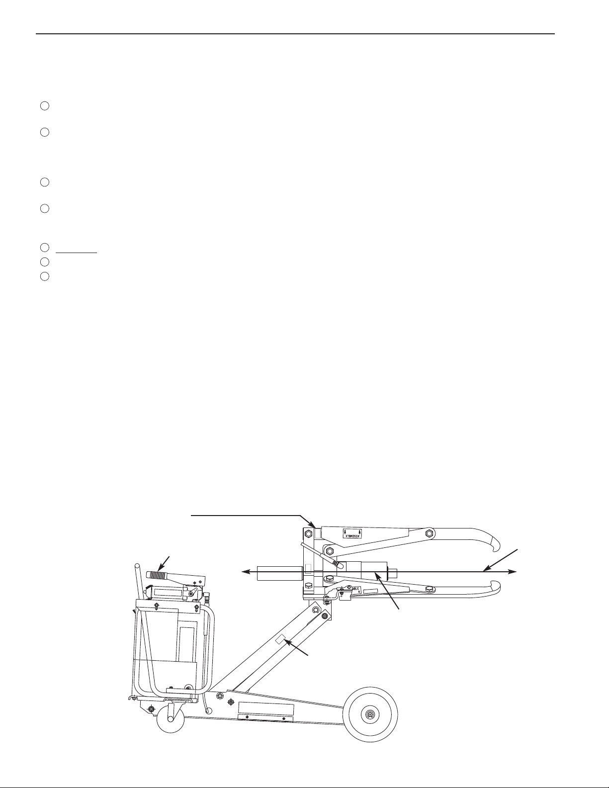
VERTICAL SET-UP
Refer to Figure 1.
The head and pulling jaw assembly on this puller is designed to compensate for some degree of error in a job set-up.
Note: Because of this feature, the head and puller jaw assembly may rest at a slight upward angle.
1. Adjust vertical set-up by using the hand pump shown in Figure 1. The centerline of the object being pulled must
be on the same
2. Align the puller horizontally and vertically as close as possible to the same centerline as the object to be pulled.
HAZARD: Crushing and cutting
centerline as the puller head.
of fingers and hand.
Hand Pump
Centerline
of object to
be removed
Puller Head
Centerline
HAZARD: Crushing of toes
FIGURE 1
or foot

Operating Instructions Form No. 102997
HORIZONTAL SET-UP
Refer to Figure 2.
1. Adjust the horizontal by positioning the puller cart as shown in Figure 2. The centerline of the object being
removed must be at approximately a 90° angle to the pulling surface engaged by the jaws and on the same
centerline as the puller cart and the puller head.
FIGURE 2
PULLER OPERATION
1. Press and hold the release button on the remote hand switch. This starts the low pressure pump which builds
pressure and opens the jaws. Open the jaws enough to allow them to fit over the work.
2. Position the cart and puller as shown in Figures 1 and 2, with the puller centered on the workpiece to be pulled.
3. Press and hold the clamp button on the remote hand switch. This starts the low pressure pump which builds
pressure and closes the jaws. When the jaws contact the work, release the clamp button and check that all the
jaws will engage with the workpiece. Note: Some clearance between the work and the flat on the jaws is
acceptable. Add as many adapters as practical to the forcing cylinder. Refer to the section of this form titled,
"Extension Adapters" on back sheet 2 of 3.
4. If the puller requires repositioning, depress the release button to open the jaws, and align again at this time.
5. Once assured of puller alignment, depress the clamp button again to close the jaws completely on the workpiece.
The low pressure pump will build to its maximum pressure, then the high pressure pump will start and advance
the forcing cylinder toward the workpiece.
Sheet No. 2 of 3
Rev. 3 Date: 18 April 06

Operating Instructions, Form No. 102997, Back sheet 2 of 3
6. At the point that the forcing cylinder contacts the workpiece, release the clamp button and inspect the puller and
workpiece for proper alignment. Note: It may be necessary to center the pushing adapters on the work.
7. Wrap the work with a Power Team protective blanket. Note: Be sure to attach a support to the work that is to
be pulled at this time. The 55 Ton Enforcer will not be able to support that work once it is pulled from the
supporting shaft.
8. Stand behind and to one side of the puller. Continue with the pulling cycle by depressing the clamp button again.
9. If full stroke of the forcing cylinder has been reached but the workpiece has not been pulled completely, press the
retract button on the remote hand switch. This will retract the forcing cylinder to allow the addition of another
forcing
when the clamp button is depressed.
adapter while maintaining the gripping action of the jaws on the workpiece. The cycle will continue again
EXTENSION ADAPTERS
Refer to Figure 3.
Extension adapters serve as spacers between the forcing cylinder and the shaft of the workpiece to be pulled.
Note: Use only Power Team pushing adapters on the end of the forcing cylinder or on the end of any
combinati
When using extension adapters, there may be sagging away from the centerline as adapters are fitted together. To
correct the alignment, use the following procedure:
1. Before applying hydraulic pressure to the workpiece, lift the pushing adapter to position it on the common
centerline of the workpiece and the puller head.
Lightly apply hydraulic pressure to hold the pushing adapter in position. Check the alignment. All adapters must
2.
be in a straight line and at a 90° angle to the object being pulled.
on of extension adapters.
251002
350593
350594
* = Exceeds 6.6 lbs.
Handle with care to avoid
personal injury.
*350637
FIGURE 3

Operating Instructions Form No. 102997
CONVERSION OF A 3-JAW PULLER TO A 2-JAW PULLER
(55 ton capacity of either 2- or 3-jaw unit)
NOTE: Whenever possible, use this puller in a 3-jaw configuration for maximum safety.
1. Remove the jaws and straps as shown in Figure 4.
2. Reassemble one set of jaws and straps as shown in Figure 5.
Remove
this jaw
Remove
this jaw
FIGURE 4
FIGURE 5
CHANGING THE RADIAL POSITION OF THE PULLER
1. When viewing the puller assembly from the rear,
loosen the three clamping bolts that are on the left
side and near the bottom of the base of the forcing
cylinder. Refer to Figure 6.
2. Rotate the puller assembly to position the two jaws
where ever convenient for your application. Refer to
Figure 7.
3. Retighten clamping bolts.
FIGURE 7
FIGURE 6
Sheet No. 3 of 3
Rev. 3 Date: 18 April 06

Operating Instructions, Form No. 102997 Back sheet 3 of 3
ROTATING THE PULLER ASSEMBLY
1. Remove the four bolts that mount the puller assembly to the cart mounting plate.
2. Rotate the puller assembly 90° in either direction.
3. Realign holes in mounting plate to the holes in the puller assembly and replace bolts.
LIFTING INSTRUCTIONS
1. Attach chains from a crane to the four lifting eye bolts (two at the front and two at the back) on the puller cart. Lift
with caution. Secure or remove all attachments before lifting. Unit Wt. = 751 lbs.
PICTOGRAMS
This pictogram means:
WORLD HEADQUARTERS
THE AMERICAS CUSTOMER
SERVICE CENTER
5885 11TH STREET
ROCKFORD, ILLINOIS 61109
TEL: 1-815-874-5556
CUSTOMER SERVICE/ORDER ENTRY
TEL: 1-800-541-1418
FAX: 1-800-288-7031
E-MAIL: INFO@POWERTEAM.COM
ASIA PACIFIC CUSTOMER
SERVICE CENTER
7 GUL CIRCLE
SINGAPORE 629563, SINGAPORE
TEL: (65) 6265-3343
E-MAIL: INFOASIA@POWERTEAM.COM
SPX HYDRAULIC TECHNOLOGIES
CHINA (CCSC)
NO: 1568, HUA SHAN ROAD,
9TH FLR INTERNATIONAL PARK CTR,
CHANGNING DISTRICT,
SHANGHAI 200052, P.R.C.
TEL: 86 (21) 2208 5888
FAX: 86 (21) 2208 5682
EMAIL: INFOCHINA@POWERTEAM.COM
WARNING: Load must
This unit is not intended to
carry any load.
EUROPEAN CUSTOMER
SERVICE CENTER
ALBERT THIJSSRAAT 12
6471 WX EYGELSHOVEN
THE NETHERLANDS
TEL: (31) 45 5678877
FAX: (31) 45 5678878
EMAIL: INFOEUROPE@POWERTEAM.COM
be supported.
 Loading...