

Power Team PG1200M-4, PG1200M-4D Operating Instructions Manual

®
Form No. 102646
SPX Corporation
5885 11th Street
Rockford, IL 61109-3699 USA
Internet Address:
http://www.powerteam.com
Tech. Services: (800) 477-8326
Fax: (800) 765-8326
Order Entry: (800) 541-1418
Fax: (800) 288-7031
Operating Instructions for:
PG1200M-4
PG1200M-4D
GAS HYDRAULIC PUMP
Max. Capacity: 10,000 PSI
NOTE:
● Read and carefully follow these instructions. Most problems with new equipment are caused by improper
operation or installation.
SAFETY PRECAUTIONS
WARNING: To help avoid personal injury,
Hydraulic Hose
● Before operating the pump, all hose connections must be tightened using the proper tools. Do not
overtighten. Connections should only be tightened securely and leak-free. Overtightening can cause
premature thread failure or high pressure fittings to split at pressures lower than their rated capacities.
● Always shut off the electric motor before breaking any connection in the system.
● Should a hydraulic hose ever rupture, burst, or need to be disconnected, immediately shut off the pump.
Never attempt to grasp a leaking pressurized hose with your hands. The force of escaping hydraulic fluid
could cause serious injury.
● Do not subject the hose to potential hazard such as fire, sharp surfaces, extreme heat or cold, or heavy
impact. Do not let the hose kink, twist, curl or bend so tightly that oil flow within the hose is blocked or
reduced. Periodically inspect the hose for wear, because any of these conditions can damage the hose.
● Do not use the hose to move attached equipment. Stress can damage the hose, causing personal injury.
● Hose material and coupler seals must be compatible with the hydraulic fluid used. Hoses also must not
come in contact with corrosive materials such as creosote-impregnated objects and some paints. Consult
the manufacturer before painting a hose. Never paint the couplers. Hose deterioration due to corrosive
materials can result in personal injury.
Parts List &
Pump
Do not exceed the PSI hydraulic pressure rating noted on the pump nameplate or tamper with the internal
●
high pressure relief valve. Creatng pressure beyond the rated capacity can result in personal injury.
● Before replenishing the oil level, retract the system to prevent overfilling the pump reservoir. An overfill
can cause personal injury due to excess reservoir pressure created when cylinders are retracted.
Cylinders
● Do not exceed the rated capacities of the cylinders. Excess pressure can result in personal injury.
● Do not set poorly balanced or off-center loads on a cylinder. The load can tip and cause personal injury.
Power Supply (Gasoline Engine)
Read the instruction manual for the gasoline engine before using.
●
● Do not allow fuel to splash on the engine when refueling.
● Do not add fuel when the engine is running or very hot.
Litho in USA
Sheet No. 1 of 7
Issue Date: Rev. 7-20-94

Parts List and Operating Instructions, Form No. 102646, Back sheet 1 of 7
A
B
SET-UP
Gasoline Engine
Refer to the instruction manual on the gasoline engine.
Hydraulic Connections
1. Clean all the areas around the oil ports of the pump and cylinders.
2. Inspect all threads and fittings for signs of wear or damage, and replace as needed.
3. Clean all hose ends, couplers or unions.
4. Remove the thread protectors from the hydraulic oil outlets. Connect the hose assembly to the hydraulic oil outlet,
and couple the hose to the cylinder. Although a high-grade, non-hardening thread sealant is preferred, teflon tape
can be used if only one layer of tape is used. Apply carefully to prevent the tape from being pinched by the
coupler and broken off inside the pipe end. Any loose pieces of tape could travel through the system and obstruct
the flow of oil.
Filling the Reservoir
NOTE: The pump has been shipped without oil in the reservoir. High-grade hydraulic oil has been shipped
with the pump in a separate container. If additional oil is required, use Power Team hydraulic fluids only.
1. Clean the area around the filler cap to remove all dust and grit. Any dirt or dust in the oil can damage the polished
surfaces and precision-fit components of this pump.
2. Retract all cylinders to the return position.
3. Remove the filler cap, and insert a clean funnel and filter. Fill with hydraulic oil to 1/2" from the top of the filler
hole. Replace filler cap with the breather-hole in the filler cap open.
4. Cycle the pump (with cylinders attached) several times. Retract the cylinders, and check the oil level in the pump
reservoir again.
OPERATION
Priming the Pump
When operating the pump for the first time:
1. Valve and hose connections must be tight, and the reservoir must be filled to the proper level. Start the motor.
2. Jog the pump several times to build pressure. If the pump doesn't build pressure, it may not be primed.
Disconnect a hose from the system and route it back to the pump reservoir. Run the pump until a steady flow of
oil is observed free of suspended air bubbles. Reconnect the hose to the system.
3. Run cylinder out to its full travel several times to eliminate air from the system. For more complete instructions,
refer to the section titled "Bleeding Air from the System."
4. The pump is ready to be put into regular operation.
IMPORTANT: After eliminating trapped air from a large work-holding system, retract the cylinders and refill
the pump reservoir to 1/2" from the top of the filler hole.
Adjusting the Pressure Regulating Valve
The pressure regulating valve can be adjusted to bypass oil at a given pressure setting while the pump continues to
run.
NOTE: For easy adjustment of the pressure regulating valve,
always adjust the pressure by
pressure setting.
1. Loosen the locknut on the pressure regulating valve (B), and
back the adjusting screw (A) out a few turns with a
screwdriver by turning in a counterclockwise direction. This
will
decrease
2. The pump must be completely connected. Set the motor
control toggle switch to "Run" and push the "Start" button.
3. With the screwdriver, slowly turn the adjusting screw (A) in a
clockwise direction. This gradually
setting. When the desired pressure is reached, lock the
adjusting screw in position by tightening the locknut.
the setting to a lower than desired pressure.
increasing
to the desired
increases
the pressure
Figure 1

Parts List and Operating Instructions Form No. 102646
PREVENTIVE MAINTENANCE
WARNING: To help avoid personal injury,
● Repairs and maintenance are to be performed in a dust-free area by a qualified technician.
Bleeding Air from the System
Upon initial start up or after prolonged use, air can accumulate within the hydraulic system. This entrapped air can
cause the system to respond slowly or behave in an unstable manner. To remove the air, loosen a fitting that is
situated higher than the rest of the fittings in the system. Run the pump until a steady flow of oil free of suspended air
bubbles is observed. Tighten the fitting.
Inspecting the Hydraulic Fluid Level
Check the oil level in the reservoir periodically. The oil level should be 1/2" from the top of the filler hole with all
cylinders retracted. Drain, clean and replenish the reservoir with Power Team hydraulic fluid yearly or more often if
necessary. The frequency of oil change will depend upon the general working conditions, severity of use and overall
cleanliness and care given the pump.
Maintenance Cleaning
1. Keep the outer surface of the pump as free from dirt as possible.
2. Protect all unused couplers.
3. Keep all hose connections free of dirt and grime.
4. Keep the filler/vent cap clean and unobstructed at all times.
5. Equipment connected to the pump must be kept clean.
6. Use only Power Team hydraulic fluids in this pump. Change as recommended.
Draining and Cleaning the Reservoir
IMPORTANT: Clean the pump exterior before the pump interior is removed from the reservoir.
1. Remove the ten screws that fasten the motor and pump assembly to the reservoir. IMPORTANT: Lift the pump
and motor off the reservoir carefully to avoid damaging the gasket or any internal components.
2. Clean the inside of the reservoir and fill half full with clean Power Team hydraulic fluid.
3. Place the pump and motor assembly back onto the reservoir and secure with two machine screws assembled on
opposite corners of the housing. IMPORTANT: Connect a hose to the pressure port on the valve. Place the
other end of the hose into the oil filler plug hole.
4. Run the pump for several minutes. Then disconnect the motor and pump assembly, and drain and clean the
inside of the reservoir.
5. Fill the reservoir with Power Team hydraulic fluid. Place the pump and motor assembly (with gasket) on the
reservoir and install all the screws. Tighten securely and evenly.
Adding Oil to the Reservoir
1. Cylinder(s) must be fully retracted and the gas engine off when adding oil to the reservoir.
2. Clean the entire area around the filler/vent cap before removing the filler/vent cap.
3. Use a clean funnel with filter when adding oil.
4. Use only Power Team hydraulic fluids.
Sheet No. 2 of 7
Issue Date: Rev. 7-20-94
Part List and Operating Instructions, Form No. 102646, Back sheet 2 of 7
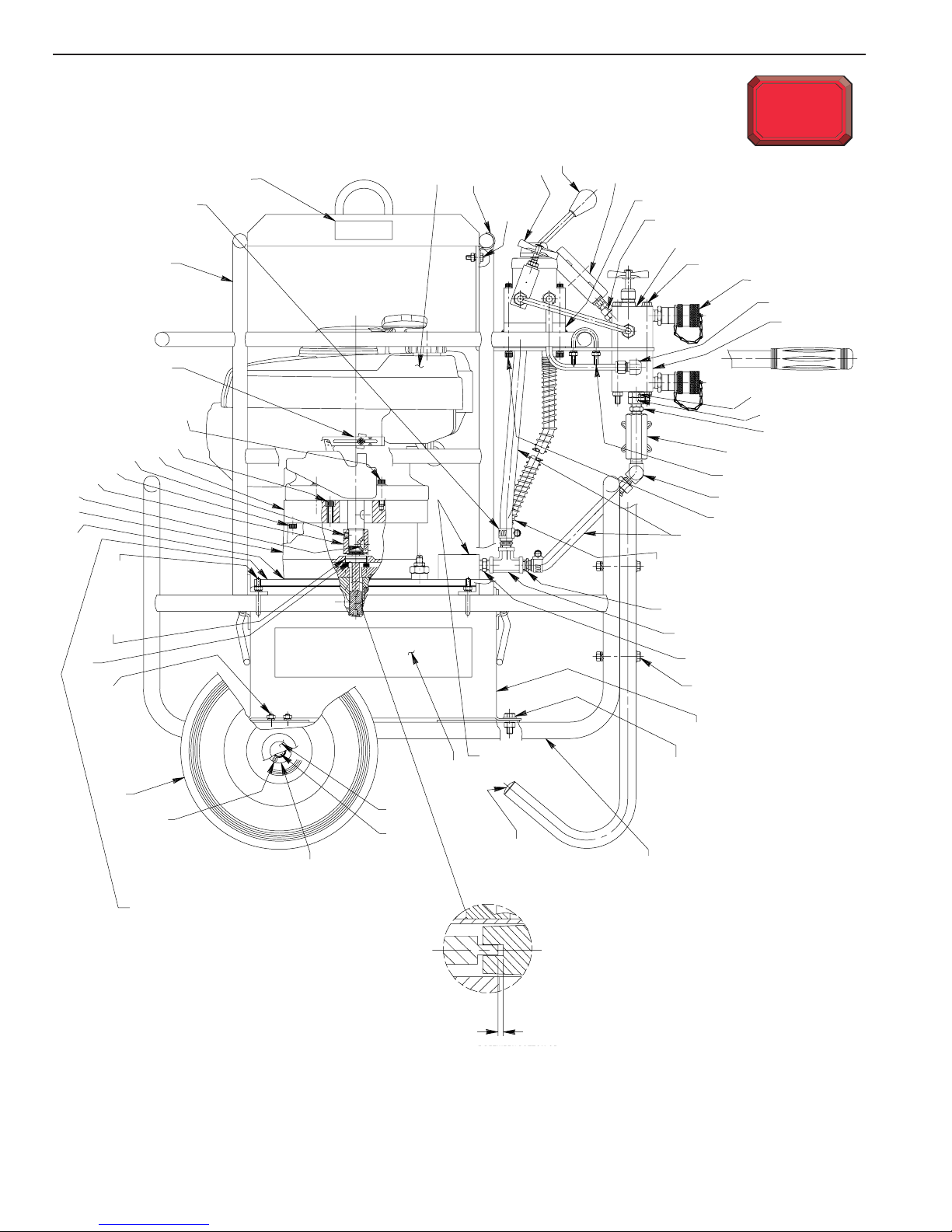
To Parts
List
SIDE VIEW
7
58
59
60
1
2
6
3
4
5
8
9
10
11
12, 13, 14
15
16
INLET
17
50
49
48
46
51
45
52
47
44
22
4
53
54
43
57
55
56
13
42
41
40
39
38
INLET
18
19
20
21
22, 4
23
24, 25
26
27
28
29
20
30, 13, 31, 14
32
33
34
35
37
36
Basic Pump Assembly
See back pg. 4 of 7
.010
.010
.040
.040
(DISTANCE BETWEEN BOTTOM OF
420052 SHAFT ADAPTER AND
(Distance between bottom of
BOTTOM OF SLOT IN 21091.)
shaft adapter [Item #51] and
bottom of slot in nylon coupler
[Item #19 on sheet 6 of 7])
 Loading...