

Power Team PE55TWP-E110, PE55TWP-E220, PE55TWP, PE55TWP-220, PE55TWP-4-E110 Operating Instructions Manual
...
Form No. 1000090
Operating Instructions for:
PE55TWP-E110
PE55TWP-E220
PE55TWP
PE55TWP-220
PE55TWP-4-E110
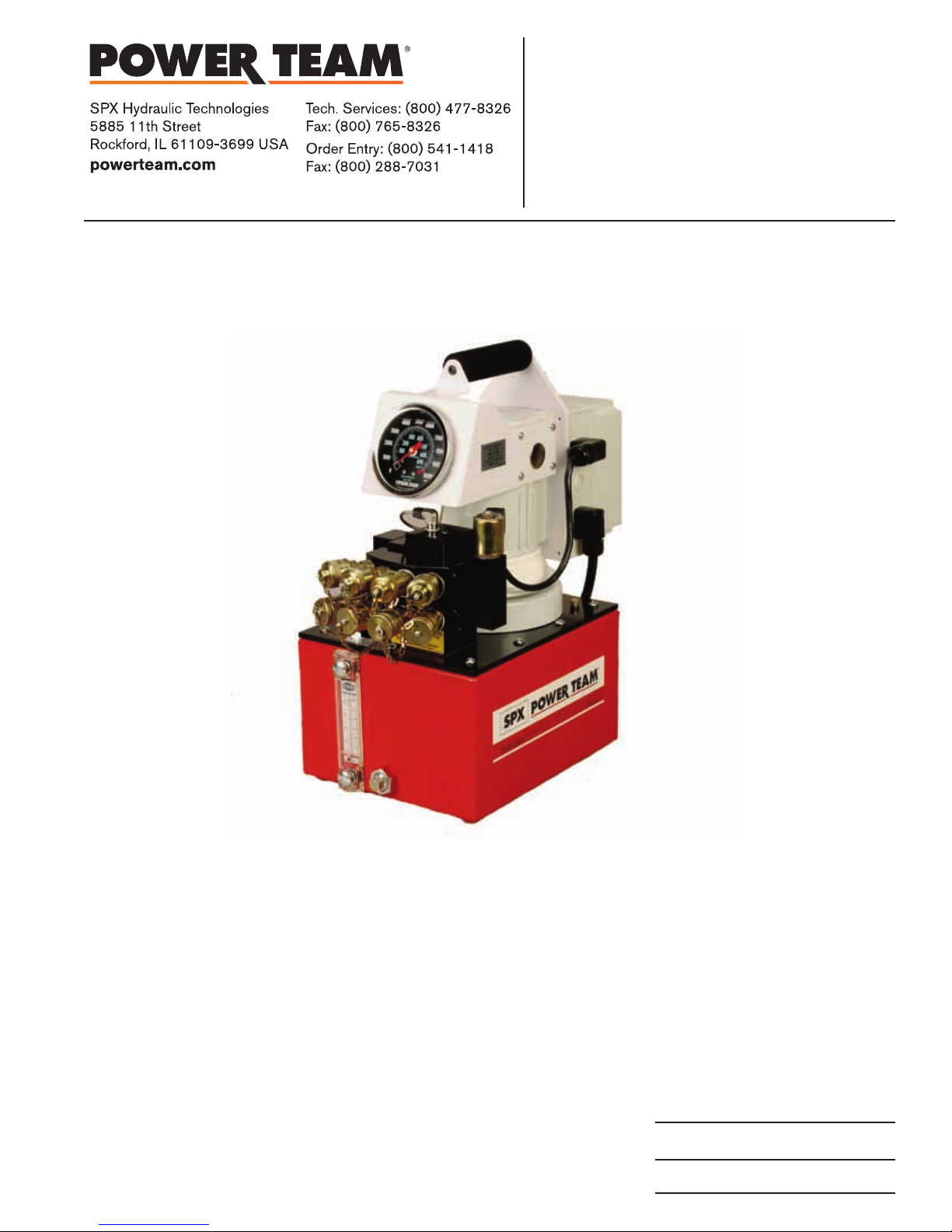
ELECTRIC HYDRAULIC PUMP
10,000 PSI
PE55TWP-4-E220
PE55TWP-4
PE55TWP-4-220
PE55TWP-CF
NOTE:
●
Carefully inspect the pump upon arrival. The carrier, not the manufacturer, is responsible for any damage
resulting from shipment.
●
Read and carefully follow these instructions. Most problems with new equipment are caused by improper
operation or installation.
●
The hydraulic power unit can be ordered with "building block" flexibility. The customer can choose from a
variety of motors, controls, reservoirs, and other options. Because of the many options available, these
instructions will include directions for options that your particular pump may not have.
●
Do not change motors without consulting the pump manufacturer's Technical Services Department.
Sheet No. 1 of 6
Rev 3 Date: 25 May 2012

Operating Instructions, Form No. 1000090, Back sheet 1 of 6
SAFETY PRECAUTIONS
WARNING: To help prevent personal injury,
HYDRAULIC HOSE
● Before operating the pump, all hose connections must be tightened with the proper tools. Do not overtighten.
Connections should only be tightened securely and leak-free. Overtightening can cause premature thread failure
or high pressure fittings to split at pressures lower than their rated capacities.
● Always shut off the electric motor before breaking any connections in the system.
● Should a hydraulic hose ever rupture, burst, or need to be disconnected, immediately shut off the pump. Never
attempt to grasp a leaking pressurized hose with your hands. The force of escaping hydraulic fluid could cause
serious injury.
● Do not subject the hose to potential hazard such as fire, sharp surfaces, extreme heat or cold, or heavy impact. Do
not let the hose kink, twist, curl or bend so tightly that oil flow within the hose is blocked or reduced. Periodically
inspect the hose for wear, because any of these conditions can damage the hose.
● Do not use the hose to move attached equipment. Stress can damage the hose, causing personal injury.
● Hose material and coupler seals must be compatible with the hydraulic fluid used. Hoses also must not come in
contact with corrosive materials such as creosote-impregnated objects and some paints. Consult the manufacturer
before painting a hose. Never paint the couplers. Hose deterioration due to corrosive materials can result in
personal injury.
PUMP
● Do not exceed the PSI hydraulic pressure rating noted on the pump nameplate or tamper with the internal high
pressure relief valve. Creating pressure beyond rated capacities can result in personal injury.
● Before replenishing the oil level, retract the system to prevent overfilling the pump reservoir. An overfill can cause
personal injury due to excess reservoir pressure created when the wrenches are retracted.
POWER SUPPLY
● Never use an ungrounded power supply with this unit.
● The pump must be compatible with existing line voltage.
● Disconnect the pump from the power supply when performing maintenance or repair on the unit.
● If the unit's power supply is damaged or the inner wiring is exposed in any way, replace immediately.
● Any electrical work must be done by a qualified electrician.
● If the power cord is damaged or wiring is exposed, replace or repair immediately.
● Changing the voltage on the jet motor (single, or three phase) is a complicated and, if not done correctly,
dangerous procedure. Consult the pump manufacturer's Technical Services Department for specific information
before attempting any rewiring. Rewiring voids CSA approval.
● All voltages must be wired for CW rotation when viewed from the lead end (top) of the motor.
● Check the total amperage draw for the electrical circuit you will be using. (For example: Do not plug a motor or
motors that may draw 25 amps into a 20 amp fused electrical circuit.)
● Do not attempt to increase the powerline capacity by replacing a fuse with another fuse of higher value.
Overheating of the powerline and the possibility of a fire will result.
● To rewire a motor from one voltage to another or when a flow control valve is changed between manual and
solenoid, consult the electrical schematic in the pump's parts list.
Circuit Breakers: If motor stops due to an overload or power outage,
Universal Motor: Move motor switch to OFF and control valve to neutral. Let motor cool or wait until power is
restored. Reset circuit breaker switch in power panel. (The pump motor doesn't have a circuit breaker.)
Single-phase Motor: Thermal overload switch will break circuit to the motor. Move motor switch to OFF and control
valve to neutral. Allow motor to cool before switching on again, or wait until power is restored.
Three-phase Motor: A magnetic starter switch breaks circuit to the motor. Move the motor switch to OFF and
control valve to neutral. Remove the cover on motor control box. Let the motor cool or wail until power is restored.
One of three reset buttons must be pushed in to reset motor. Replace cover.

Operating Instructions Form No. 1000090
HYDRAULIC PUMP SET-UP PROCEDURE
Motor Hook-up and Operation
Universal Motor: The universal motor is wired for 115 or 230 volts, 50/60 cycles according to the customer's request.
This motor cannot be rewired.
SET-UP AND OPERATION
Filling The Reservoir
NOTE: The pump has been shipped without oil in the reservoir. High-grade hydraulic oil has been shipped
with the pump in a separate container. If additional oil is required, use a high-grade, approved hydraulic oil.
1. Clean the area around the filler cap to remove all dust and grit. Any dirt or dust in the oil can damage the polished
surfaces and precision-fit components of the pump.
2. Retract all cylinders to the return position.
3. Remove the filler cap, and insert a clean funnel and filter. Fill with hydraulic oil to 1/2" from the top of the filler hole.
Replace filler cap with the breather-hole in the filler cap open.
4. Cycle the pump (with wrench attached) several times. Retract the wrench, and check the oil level in the pump
reservoir again.
Hydraulic Connections
1. Clean all the areas around the oil ports of the pump and wrench.
2. Inspect all threads and fittings for signs of wear or damage, and replace as needed.
3. Clean all hose ends, couplers or union ends.
4. Remove the thread protectors from the hydraulic oil outlets. Connect the hose assembly to the hydraulic oil outlet,
and couple the hose to the wrench. Although a high-grade, non-hardening thread sealant is preferred, PTFE tape
may be used to seal hydraulic connections if only one layer of tape is used. Apply carefully to prevent the tape
from being pinched by the coupler and broken off inside the pipe end. Any loose pieces of tape could travel
through the system and obstruct the flow of oil.
Sheet No. 2 of 6
Rev 3 Date: 25 May 2012
Operating Instructions, Form No. 1000090, Back sheet 2 of 6
1000
2000
3
000
4
000
5000
6000
7000
8000
9000
10000
PSI
bar
690
600
500
4
00
3
00
200
100
0
0
USE ONLY
FOR HYDRAULIC
MADE IN U.S.A.
1.04
B I
S
NA
htiw
sei
l
p
mo
C
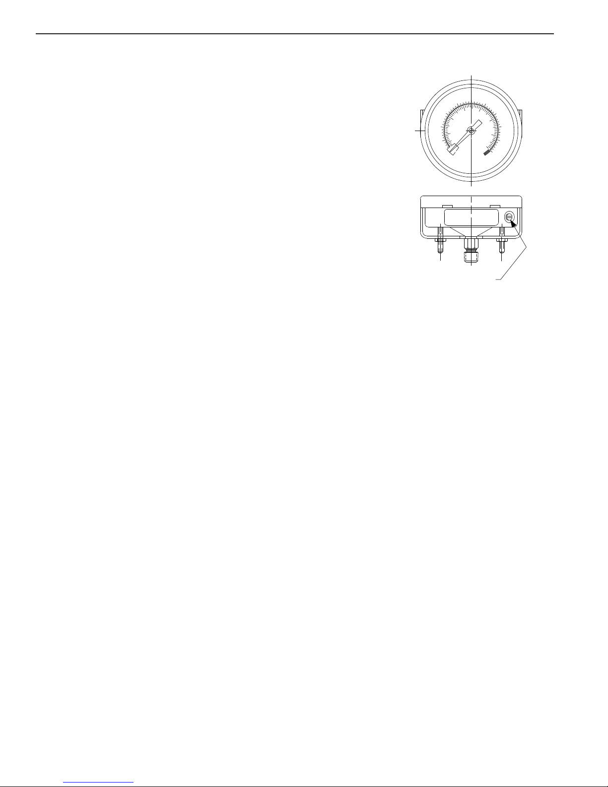
External
Adjustment Screw
Adjusting The Hydraulic Gauge
Locate the adjustment screw on the gauge (see Figure 1) and make
adjustments as needed with a screwdriver. The adjustment screw is located on
the lower right back rim of the gauge. You must reach under the portion of the shroud
that the gauge is mounted in.
Priming The Pump
FIGURE 1
When operating the pump for the first time:
1. Valve and hose connections must be tight, and the reservoir must be filled to the proper oil level. Start the motor.
2. Jog the pump several times to build pressure. If the pump doesn't build pressure, it may not be primed.
Disconnect a hose from the system and route it back to the pump reservoir. Run the pump until a steady flow of
oil is observed free of suspended air bubbles. Reconnect the hose to the system.
3. Run wrench several times to eliminate air from the system. For more complete instructions, refer to the section
titled "Bleeding Air From The System."
4. The pump is ready to be put into regular operation.
IMPORTANT: After eliminating trapped air from a large work-holding system, retract the wrenchs and refill
the pump reservoir to 1/2" from the top of the filler hole.
Adjusting The Pressure Regulating Valve
NOTE: For easy adjustment of the pressure regulating valve, always adjust the pressure by
desired pressure setting.
1. Loosen the locknut on the pressure regulating valve (C), and back the adjusting screw (B) out a few turns with a
screwdriver by turning in a counterclockwise direction. This will
2. The pump must be completely connected. Set the motor control toggle switch on "Run" and push the "Start"
3. With the screwdriver, slowly turn the adjusting screw (B) in a clockwise direction. This gradually
pressure.
button.
decrease
the setting to a lower than desired
pressure setting. When the desired pressure is reached, lock the adjusting screw in position by tightening the
locknut.
increasing
increases
to the
the
IMPORTANT:
●
The pressure range is from 1,000 to 10,000 PSI depending on the pump model.

Operating Instructions Form No. 1000090
PREVENTIVE MAINTENANCE
WARNING: To help prevent personal injury,
●
Disconnect the pump from the power supply before performing maintenance or repair procedures.
●
Repairs and maintenance are to be performed in a dust-free area by a qualified technician.
Bleeding Air From The System
Air can accumulate in the hydraulic system if the reservoir oil level is too low. This air causes the wrench to respond
in an unstable or slow manner. To remove the air:
1. The hydraulic wrench(s) must be positioned on their side(s) with the couplers located upward.
2. Remove any load from the wrench(s), and cycle the hydraulic system through several cycles (fully extend and
retract the wrenchs).
Note: The wrench must be at a lower level than the pump to allow air to be released through the pump
reservoir
Hydraulic Fluid Level
1. Check the oil level in the reservoir after each 10 hours of use. Proper oil level is 1/2" from the top of the fill hole
when all wrenches are retracted.
2. Drain, flush, and refill the reservoir with an approved, high-grade hydraulic oil after approximately every 300 hours
of use. The frequency of oil changes will depend upon the general working conditions, severity of use, and overall
cleanliness and care given the pump.
Maintenance Cleaning
1. Keep the pump's outer surface as free from dirt as possible.
2. Seal all unused couplers with thread protectors.
3. Keep all hose connections free of dirt and grime.
4. The breather-hole in the filler cap must be clean and unobstructed at all times.
5. Equipment connected to the pump must be kept clean.
6. Use only an approved, high-grade hydraulic oil in this pump. Change as recommended (every 300 hours).
Sheet No. 3 of 6
Rev 3 Date: 25 May 2012

Operating Instructions, Form No. 1000090, Back sheet 3 of 6
Draining And Flushing The Reservoir
IMPORTANT: Clean the pump exterior before the
pump interior is removed from the reservoir.
1. Remove the ten screws fastening the motor and
pump assembly to the reservoir. IMPORTANT: Do
not damage the gasket or bump the filter or
pressure regulating valves when lifting the pump
and motor off the reservoir. See Figure 2.
2. Clean the insi de of the reservoir and fill with a
suitable flushing oil. Rinse the filter clean.
3. Place the pump and motor assembly back onto the
reservoir, and secure with two machin e scre ws
assembled on opposite corners of the housing.
IMPORTANT: The hydraulic flow control valve must
be in the neutral position for the following step. If
the pump is equipped with a valve that has only an
advance or retract position, place the valve in the
adv ance p osi tion , and con nect a h ose to the
advance port on the valve. Place the other end of
the hose into the oil filler plug hole.
4. Run the pump for several minutes. Then disconnect the motor and pump assembly, and drain and clean the
inside of the reservoir.
5. Fill the reservoir with an approved, high-grade hydraulic oil. Place the pump and motor assembly (with gasket) on
the reservoir, and thread the ten screws. Tighten securely and evenly.
FIGURE 2
Adding Oil To The Reservoir
1. Wrench must be fully retracted and the power supply disconnected when adding oil to the reservoir.
2. Clean the entire area around the filler plug before removing the filler plug.
3. Use a clean funnel with filter when adding oil.
4. Use an approved, high-grade hydraulic oil (215 SSU @ 100° F) only.
Sound Reduction
The electrically-powered hydraulic pump operates in the 90-95 dBA range. If further sound reduction is desirable, any
of the following options will help reduce the sound level.
1. Install a pressure switch. It shuts the motor off automatically when maximum pressure is reached (holding cycle).
2. Use a 3450 RPM, 1-1/2 horsepower, 115 VAC, 60 Hz, 1-phase pumping unit.
3. Use a 3450 RPM, 1-1/2 horsepower, 230 VAC, 60 Hz, 3-phase pumping unit.
4. Install casters (two gallon reservoir only) to reduce the noise level.
Checking Brushes On Universal Motors
To help prevent premature failure of the armature,
check the brushes periodically:
1. Remove the metal brush cover plates.
2. Remove the brush holder caps and brush assemblies
3. The brush assemblies must be replaced if they are 1/8" long or less.
See Figure 3.
4. Install brush assemblies, brush holder caps, and metal brush cover plates.
Replace when
1/8" lg. or less
7/8"
(new)
FIGURE 3

Operating Instructions Form No. 1000090
REASSEMBLY SPECIFICATIONS
HIGH PRESSURE PUMP ASSEMBLY
BOLT TIGHTENING SEQUENCE
NEEDLE BEARING INSTALLATION
BRUSH HOLDER & ARMATURE
INSTALLATION SPECIFICATIONS
SPECIFICATIONS
Sheet No. 4 of 6
Rev 3 Date: 25 May 2012

Operating Instructions, Form No. 1000090, Back sheet 4 of 6
TROUBLESHOOTING GUIDE
WARNING
●
To help prevent personal injury, any repair work or troubleshooting must be done by qualified personnel
familiar with this equipment.
●
Use the proper gauges and equipment when troubleshooting.
NOTE:
●
Depending on the type of pump, it is often best to check for leaks by using a hand pump and applying
pressure to the suspect area without the motor running. Watch for leaking oil and follow it back to its
source.
●
Plug the outlet ports of the pump when checking for leakage to determine if the leakage is in the pump or
in the wrench or tool.
●
Refer to the Parts List included with your particular pump when using this troubleshooting guide.
PROBLEM CAUSE SOLUTION
Electric motor does not run
WARNING: To help prevent
personal injury, disconnect
power supply before removing
cover. Any electrical work should
be performed by a qualified
electrician.
1. Pump not turned ON.
2. Unit is not plugged in.
3. No voltage supply.
4. Broken lead wire or defective
power cord plug.
5. Defective switches.
6. Defective motor.
7. Defective starter relay.
8. Defective remote switch.
9. Worn brushes.
10. Circuit breaker tripped because
total amperage draw too high for
existing circuit.
11. Overheated motor (single-phase
motor only). Magnetic starter
disengaged (three-phase motor
only). Thermal protector open.
12. Faulty thermal protector (singlephase motor). Faulty magnetic
starter (three-phase motor).
1. Flip toggle switch to "Run"
position.
2. Plug in unit.
3. Check line voltage. Check reset
button on power panel.
4. Replace defective parts.
5. Check switches.
6. Repair or replace motor.
7. Replace defective parts.
8. Repair or replace remote switch.
9. Replace brushes.
10. Add an additional circuit or use
alternate circuit.
11. Wait for motor to cool before
restarting. Reset thermal
protector (Single-phase motor
will reset automatically.)
12. Replace.

Operating Instructions Form No. 1000090
PROBLEM CAUSE SOLUTION
Pump is not delivering oil or
delivers only enough oil to
advance wrench(s) partially or
erratically (continued).
1. Oil level too low.
2. Loose-fitting coupler to wrench.
3. Air in system.
4. Air leak in suction line.
5. Dirt in pump or filter plugged.
6. Oil is bypassing through the
double-acting wrench.
7. Cold oil or oil too heavy
(Hydraulic oil is of a higher
viscosity than necessary).
8. Relief valve or low pressure
unloading valve out of
adjustment.
9. Reservoir capacity is too small
for the size of the wrench(s)
used.
10. Defective directional valve.
11. Sheared drive shaft key(s)
12. Motor rotating in wrong
direction.
13. Vacuum in reservoir.
14. Low pressure pump worn.
1. Fill reservoir to 1/2" from top of
filler hole with wrench retracted.
2. Check quick-disconnect
couplings to wrench. Inspect
couplers to ensure that they are
completely coupled.
Occasionally couplers have to
be replaced because the ball
check does not stay open due to
wear.
3. Bleed the system.
4. Check and tighten suction line.
5. Pump filter should be cleaned
and, if necessary, pump should
be dismantled and all parts
inspected and cleaned.
6. By removing the wrench and
capping the hoses, the pump
and valve can be checked.
Observe if pump holds
pressure.
7. Change to a lighter oil.
8. Adjust as needed.
9. Use smaller wrench(s) or larger
reservoir.
10. Inspect all parts carefully and
replace if necessary.
11. Replace.
12. 3450 RPM motor: Refer to
electrical schematic on motor.
12,000 RPM motor: Reverse
lead wires to brush holders.
Air motor: Air line connected
into wrong port.
13. Check for plugged vent in filler
plug.
14. Remove end cap from low
pressure gear pump. Clean
pump, and replace worn gears,
shifting spool, body or end cap.
Sheet No. 5 of 6
Rev 3 Date: 25 May 2012

Operating Instructions, Form No. 1000090, Back sheet 5 of 6
PROBLEM CAUSE SOLUTION
Pump builds pressure but cannot
maintain pressure.
Pump will not build full pressure. 1. Faulty pressure gauge.
1. Check to see if there are any
external leaks. If no oil leakage
is visible, the problem is
internal. If using a doubleacting wrench, remove it from
the system to ensure that the
leak is not in the wrench.
2. To test for a leaking control
valve, lift the pump from the
reservoir but keep the filter in
the oil. Remove the drain line to
see if the oil is leaking from the
valve. If the valve is not leaking,
the internal check valve could
be leaking. Refer to the note
concerning checking for oil
leaks at the beginning of this
troubleshooting Guide.
3. Leaking pressure switch seal.
2. Check for external leakage.
3. Check the external pressure
regulator. Check the relief valve
setting.
4. Look for internal leakage in
double-acting wrench.
5. Check for leaks in the flow
control valve.
6. Inspect the pump for internal
leakage. Check high pressure
pump inlet or outlet ball checks.
1. Seal leaking pipe fittings with
pipe sealant.
2. Clean, reseat or replace flow
control valve parts. If the
internal check valve(s) are
leaking, the pump must be
dismantled and the seat areas
repaired, poppets replaced, etc.
3. Repair or replace seal.
1. Calibrate gauge.
2. Seal faulty pipe fitting with pipe
sealant.
3. Lift the pump from the reservoir,
but keep the filter immersed in
oil. Note the pressure reading
when the relief valve begins to
open. If functioning normally, it
should start to leak off at relief
valve pressure.
4. Remove the wrench from the
pump. If the pump builds full
pressure, the wrench is
defective.
5. Clean and reseat or replace
parts.
6. Same procedure as above, but
look for leaks around the entire
inner mechanism. If there are
no visible leaks, the high
pressure pump subassembly
may be leaking. Remove all
parts. Check the valve head
assembly body for any damage
to the seat area. Clean and
reseat if necessary. Inspect for
damage and replace if
necessary, then reassemble.

Operating Instructions Form No. 1000090
PROBLEM CAUSE SOLUTION
Pump will not build full pressure.
(Continued)
Wrench will not retract. 1. Check the system pressure; if
7. Sheared key(s).
8. Inadequate air pressure (air
motor only).
9. Shifting spool seat and/or
shifting spool poppet (located
under high pressure pump
assembly) worn.
10. Shifting spool o-ring (located
within shifting spool bore) worn
or broken.
the pressure is zero, the control
valve is releasing pressure and
the problem may be in the
wrench, mechanical linkage
connected to wrench(s), or
quick-disconnect couplings.
2. Defective valve.
3. Inadequate air pressure (air
motor model only).
7. Replace.
8. Increase air pressure.
9. Clean and reseat or replace.
10. With an o-ring pick, remove
o-ring and backup washer
through low pressure pump
assembly end. Replace.
1. Check the wrench for broken
return springs, and check
couplers to ensure that they are
completely coupled.
Occasionally couplers have to
be replaced because one check
does not stay open in the
coupled position.
2. Check valve operation and
inspect parts. Replace if
necessary.
3. Increase air pressure.
Pump delivers excess oil
pressure.
1. Faulty pressure gauge.
2. Relief valve not properly set.
1. Calibrate gauge.
2. Adjust the relief valve.
Sheet No. 6 of 6
Rev 3 Date: 25 May 2012
 Loading...