

Power Team C12-HTR series, 12-HTR series Operating Instructions And Parts List Manual
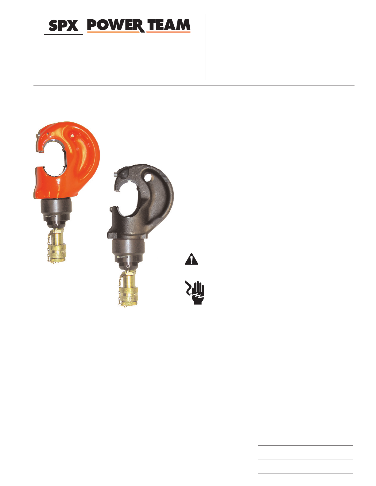
C12-HTR / 12-HTR REMOTE HYDRAULIC
CRIMPING TOOL
Form No. 1000023A
C12-HTR-C SERIES
12-HTR SERIES
Operating Instructions and
Parts List for:
INTRODUCTION
The 12-HTR compression head was designed for installing
tubular compression connectors on electrical conductors.
The 12-HTR remote compressor is a light weight, remote
powered, hydraulic tool that can be operated in any position.
The single acting cylinder develops twelve tons of thrust at
10,000 psi (68.9 MPa). Any pump capable of this pressure,
with a safety valve setting between 9,600 psi (66.2 MPa) and
10,400 psi (71.7 MPa) may be used.
The 0.92 inch (23.4 mm) open C-head permits the
compressor to be hooked over the conductor or accessory,
and the die locking devices allow it to be moved along without
accidentally dislodging the die halves.
THE 12 HTR AND C12-HTR TOOL IS NOT TO BE USED
FOR "HOT LINE" WORK.
SPECIFICATIONS
TOOL SECTION:
1.81 (4.60 CM) DIA.RAM, .96 (2.44 CM) STROKE WITH DIES.
CRIMPING FORCE, 13.1 U.S. TONS AT10,000 PSI (11.9 METRIC TONS
AT 70,000 kPA (700 BAR)
OIL TYPE USED, AMOCO RYKON MV.
OVERALL DIMENSIONS:
2.75 x 4.87 x 10.25 INCHES LONG (6.98 x 12.37 x 26.03 CM LONG)
TOTAL WEIGHT, 10.3 LBS. WITH OIL (4.7 kg WITH OIL)
CRIMPING CAPACITY:
NO.8 THRU 500 MCM CU GROUNDING TERMINALS AND SPLICES
NO.8 THRU 250 MCM CU GROUNDING TAPS AND 3/4 INCH GROUND ROD
NO.8 THRU 750 MCM CU INSULATED AND UNINSULATED TERMINALS
NO.8 THRU 750 MCM CU ALUMINUM TERMINALS
NO.8 THRU 350 MCM CU ALUMINUM SPLICES
NO.6 THRU 556.5 26/7 ACSR STRANDING
COUPLERS:
MALE COUPLER ASSEMBLY (Power Team Part No. 25599)
WARNING
Sheet No. 1 of 5
Rev 1 Date: 13 June 2005
© 2005 SPX Corporation
SPX Corporation
5885 11th Street
Rockford, IL 61109-3699 USA
Internet Address:
http://www.powerteam.com
®
Tech. Services: (800) 477-8326
Fax: (800) 765-8326
Order Entry: (800) 541-1418
Fax: (800) 288-7031
Operating Instructions and Parts List, Form No. 1000023A, Back sheet 1 of 5
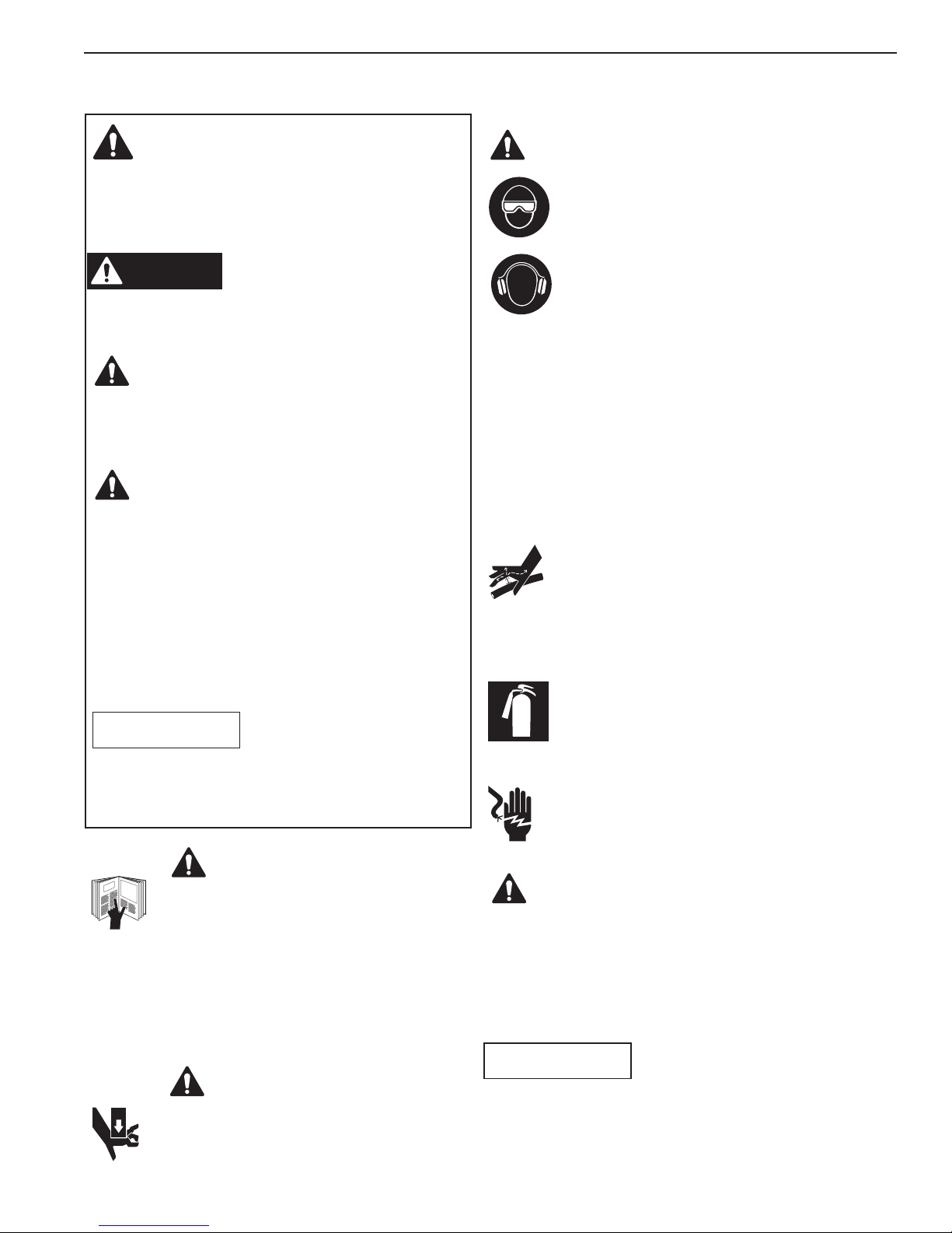
IMPORTANT SAFETY INFORMATION
This is the safety alert symbol.
It is used to alert you to potential personal injury
hazards. Obey all safety messages that follow this
symbol to avoid possible injury or death
Denotes an imminently hazardous situation which, if
not avoided, will result in death or serious injury.
Denotes a potentially hazardous situation which, if not
avoided, could result in death or serious injury.
Denotes a potentially hazardous situation which, if not
avoided, may result in minor or moderate injury.
Caution used without the safety alert symbol indicates
a potentially hazardous situation which, if not avoided,
may result in property damage.
Denotes an operating or service procedure or condition
considered essential for expedient and efficient
operation and service.
It is the operators responsibility to read and
understand the following safety statements,
• Only qualified operators should install, operate,
adjust, maintain, clean, repair, or transport this
machinery.
• Inspect tool before use. Replace any worn or
damaged parts. Failure to observe these warnings
can result in severe injury or death.
Keep hands away from the crimping tool head
when crimping.
IMPORTANT
To help prevent personal injury,
• Always wear eye protection whenever
operating hydraulic equipment.
• Always wear hearing protection as
required.
• Operation, repair, or maintenance of hydraulic
equipment should be performed by a qualified
person who understands the proper function of
hydraulic equipment per local directives and
standards.
• Hydraulic equipment must be assembled correctly
and then checked for proper function before use. Use
hydraulic components of the same hydraulic
pressure ratings. An appropriate hydraulic pressure
gauge is recommended to monitor pressure.
• Never place your hands or other body
parts near a hydraulic fluid leak.
• Never use your hands or other body parts
to check for a possible leak.
High pressure fluid can be injected under your skin
causing serious injury and/or infection.
• Exercise caution to avoid the risk of fire.
An incomplete crimp can cause a fire. Use
proper die, connector and cable. Improper
combinations can result in an incomplete
crimp.
• DO NOT USE FOR HOT LINE WORK
• This tool is not insulated. When using this
unit near energized electrical lines, use
proper personal protective equipment.
• This tool is intended for two-handed operation.
Maintain a firm grip on both handles during
operation. Using this tool in any other manner can
result in injury or equipment damage.
• Do not advance Ram without Dies inserted.
• Properly dispose of all fluids, components, and
assemblies at the end of their useful life.
• Hydraulic fluid should be compatible with all
hydraulic components.
IMPORTANT
CAUTION
CAUTION
CAUTION
WARNING
WARNING
WARNING
WARNING
DANGER

Operating Instructions and Parts List, Form No. 1000023A
OPERATING INSTRUCTIONS
DO NOT OPERATE THE COMPRESSOR WITHOUT DIES.
Select the proper dies for use on the accessory to be compressed. Push the die release button on the C-head and
slide one of the identical die-halves into position. The die retainer pin locks the die in place.
The connection of the compressor and the hydraulic hose is quickly and easily made by the use of a quick coupler,
the female half being part of the compressor and the male half located on one end of the hydraulic hose. With this
connection properly made, the ball check valves in both female and male halves of the quick coupler are open to
permit free oil flow.
Connect compressor and hose to any suitable hydraulic pump that has a pressure output of 10,000 psi. The mating
half of quick coupler supplied with compressor is Power Team No. 25599. Pump should be equipped with a 2 or 3-way
valve. Put the valve in the retract position and retract compressor piston fully.
Place the compressor in position over the accessory to be compressed. If the accessory is larger in diameter than the
throat opening of the C-head, put the compressor over the conductor and then slide it over the accessory in the
correct position for the first compression.
Place valve in advance pisition and advance piston with pump. When the dies touch on the frame side, compression
is complete.
Release the pressure at the pump and the lower die-half will retract. When compressing connectors, overlap each
bite of the dies just enough to make a smooth continuous compressed section.
Do not use the compressor for any purpose other than that for which it was designed.
This tool has been manufactured to precision tolerances. It should be used with the
same care and attention as any other fine piece of equipment.
REPLACING HYDRAULIC SEALS
Maintenance and repair of this tool should be provided with the same reasonable care given other fine equipment.
Service should be performed by adequately trained personnel in repair shops under clean conditions. For those
owners having adequately staffed repair facilities, a hydraulic seal replacement kit No. 4-1075 containing O-rings,
gaskets, etc., needed for one complete replacement of hydraulic seals in the compressor. Include compressor serial
number when ordering all parts.
To replace the seals it is necessary to separate the C-head and piston assemblies from the cylinder. Remove both
die halves. Removing the quick coupler drains the oil and aids in dis-assembly. Remove screw and washer to unlock
cylinder.
Unscrew the C-head and the piston will also rotate. After nine complete turns the piston spring rod is unthreaded
from within the cylinder and the piston guide arrangement should be removed. Further rotation will separate the Chead from the cylinder. Pull the piston from the cylinder. All seals and rings are now accessible.
Reassemble with clean parts lubricated with the same grade of oil used in the remote pump.
The steel piston washer and leather wiper are installed on the outside of the piston with the steel washer next to the
shoulder on the piston.
Insert piston into cylinder, rotate assembly until hand tight. Backoff one-half turn to permit the piston wipers to center
themselves in the C-head bore. Thread the C-head onto the cylinder until the bottom of the die groove in piston is
flush at a corresponding point on the C-head. Continue rotation until the key slots align. At this attitude, top of piston
should not have entered C-head opening and a die-half can be inserted in piston groove.
Reassemble the piston guide arrangement with Loctite on screw threads.
WARNING
WARNING
Sheet No. 2 of 5
Rev 1 Date: 13 June 2005
 Loading...