

Istruzioni per l’uso e manutenzione
Cod. OQ7.5ARG114 – GB
Emiss. 19-01-11 Rev. 0 - Agg. /
1
POWER SYSTEM SRL
Via dell’Emigrante, 11/13 - 36040 Brendola (VI) Italia
INSTRUCTION AND
MAINTENANCE MANUAL
FOR SCREW COMPRESSORS
Models:
PS2030/2037PM
Manufacturer : POWER SYSTEM s.r.l.
Via Dell’Emigrante, 11/13
36040 Brendola, Vicenza, ITALY
Tel. +39 – 0444 - 401270
Fax +39 – 0444 - 401165
e-mail: info@powersystem.it
web: http://www.powersystem.it
Local Power System agent Name__________________________________________
Address________________________________________
Telephone______________________________________
Fax___________________________________________
Codice 900246
OQ7.5ARG114

Istruzioni per l’uso e manutenzione
Cod. OQ7.5ARG114 – GB
Emiss. 19-01-11 Rev. 0 - Agg. /
2
POWER SYSTEM SRL
Via dell’Emigrante, 11/13 - 36040 Brendola (VI) Italia
INSPECTION REPORT
Power System srl, via Dell’Emigrante 11/13, 36040 Brendola (VI) declares that the screw
compressor package:
Has successfully passed internal testing.
The following aspects were checked:
− All the components have been correctly assembled and tightened.
− Functioning of all the electric components complies with specified parameters.
− All electrical tests on safety have been carried out and found within set limits.
− Parts subjected to pressure have been tested and found satisfactory.
− There are no leakages in the oil circuit and the air circuit.
− There are no flaws in the external appearance of the machine.
− Capacity, absorbed power and various operating temperature have been checked and
found satisfactory.
Power System
The Inspector
Attention!
Failure to observe and apply the rules and recommendations listed in this manual
invalidates all types of guarantee on the compressor.
Power System declines all responsibility with regard to damage caused to persons and/or things as a result of
incorrect use of the compressor and its accessories, lack of maintenance or neglect and, in general, the failure to
observe the warnings given in this manual, which are to be considered as complementary to the general safety
standards in force.

Istruzioni per l’uso e manutenzione
Cod. OQ7.5ARG114 – GB
Emiss. 19-01-11 Rev. 0 - Agg. /
3
POWER SYSTEM SRL
Via dell’Emigrante, 11/13 - 36040 Brendola (VI) Itali
a
Dear Customer,
First of all we thank you for your trust in buying your new “Rotary screw compressor”.
We are sure that you will be satisfied with your purchase, considering the technological level achieved by our products, thanks to
our constant commitment which encourages us to grow every day and to cope professionally with the continuous technological,
productive and commercial transformations.
In the certainty that we will be able to fulfil all your future working requirements, we remain at your disposal for any information
you may require and take this opportunity of wishing you every success in your work.
Before using the machine, please fill in the document and return it to us, following the indications given below.
AUTHORISED DEALER
Company
…………………………………………………………………………………………………………………………………………………………………………
Street
…………………………………………………………………………………………………………………
No.
…………………………………
Town
…………………………………………………………………………………………………………………………………………………………………………
Province
…………………………………………………………………………………………………………………………………………………………………………
Postcode
……………………………………………………………
Stamp
Country
……………………………………………………………
Telephone
……………………………………………………………
Fax
……………………………………………………………
VAT No.
……………………………………………………………
Internet
www.
…………………………………………...…………………………………………...…………………………………………...……………………….
E-mail
…………………………………………………………………………………………………………………………………………………………………………

Istruzioni per l’uso e manutenzione
Cod. OQ7.5ARG114 – GB
Emiss. 19-01-11 Rev. 0 - Agg. /
4
POWER SYSTEM SRL
Via dell’Emigrante, 11/13 - 36040 Brendola (VI) Italia
1 WARNING
WARNING
1) Within the limits established in this guarantee, the undersigned manufacturer undertakes to repair all
construction defects that may arise during the guarantee period, set at 12 (twelve) months from the date of start
or at 15 (fifteen) months from the date of delivery.
The obligations deriving from the guarantee cease in the event of suspension or variation of the agreed terms of
payment.
2) The guarantee ceases if the buyer does not correctly follow the rules described in the “Instructions for use and
maintenance” of the compressor.
3) The guarantee does not cover: faults and defects due to normal wear of those parts which are by nature subject
to rapid and continuous wear and faults resulting from the use of tools and accessories not supplied directly by the
manufacturer.
4) In order to benefit from the right to the guarantee, when the defect arises the purchase must promptly notify the
manufacturer, at any rate no later than 8 (eight) days after the date of discovering the fault, and must allow
the manufacturer, if necessary, to carry out the required inspections and repairs.
5) The buyer must send the faulty part, covered by the guarantee, at his own expense to the manufacturer for
repair or replacement. As contemplated in this clause, the guarantee obligation is considered fulfilled with the
delivery to the buyer of the adequately repaired or replaced part.
6) During the guarantee period contemplated in clause 1) the labour costs, for the duration of the work alone, will
be at the manufacturer’s expense.
If the repairs or replacements have to be carried out on the place of installation of the compressor, the travel and
lodging expenses of the personnel will be borne by the buyer.
7) All breakages resulting from incorrect manoeuvres, lack of skill, fortuitous events or for which the user can be
held responsible, are excluded from the guarantee, whether the user is directly responsible or through a third
party, or when the buyer has made modifications or carried out repairs without the manufacturer’s consent in
writing, irrespective of whether or not there is a connection between said modifications or repairs and the defects
found.
8) It is expressly agreed that the manufacturer shall be relieved of all responsibility for any damage of lost or
decreased production suffered by the buyer, resulting from faults or defects in construction for which this
guarantee is applicable.

Istruzioni per l’uso e manutenzione
Cod. OQ7.5ARG114 – GB
Emiss. 19-01-11 Rev. 0 - Agg. /
5
POWER SYSTEM SRL
Via dell’Emigrante, 11/13 - 36040 Brendola (VI) Itali
a
INDICE
1 WARNING ................................................................................................................................................................ 4
2 EC DECLARATION OF CONFORMITY ........................................................................................................... 8
2.1 CE MARKING.................................................................................................................................................................. 9
3 IMPORTANCE OF THE MANUAL............................................................................................................................ 10
3.1 NOTES FOR CONSULTATION ................................................................................................................................... 10
3.2 INTENDED RECEIVERS (AUTHORISED OPERATORS)......................................................................................... 11
3.3 MACHINE OFF STATUS.............................................................................................................................................. 12
3.4 ABBREVIATIONS......................................................................................................................................................... 12
3.5 RESERVED RIGHTS..................................................................................................................................................... 12
4 NAMING OF THE COMPRESSOR...................................................................................................................... 13
4.1 NAMING OF THE MODELS ........................................................................................................................................ 13
4.2 NAMING OF THE COMPONENTS ............................................................................................................................. 13
5 OVERALL DIMENSIONS (MM) .......................................................................................................................... 16
6 TECHNICAL DATA ............................................................................................................................................... 17
7 INTENDED USE...................................................................................................................................................... 18
7.1 ENERGY SUPPLY SOURCES...................................................................................................................................... 18
7.2 STAGES OF USE........................................................................................................................................................... 18
7.3 LIMITS OF USE............................................................................................................................................................. 18
7.4 OPTIONAL ACCESSORIES ......................................................................................................................................... 19
8 TRANSPORT OF THE COMPRESSOR.............................................................................................................. 19
8.1 PACKAGING ................................................................................................................................................................. 19
9 UNPACKING AND HANDLING .......................................................................................................................... 20
9.1 LIFTING AND HANDLING THE MACHINE ............................................................................................................. 20
10 INSTALLATION..................................................................................................................................................... 21
10.1 GENERAL WARNINGS................................................................................................................................................ 22
10.2 POSITIONING ............................................................................................................................................................... 22
10.3 SECURING THE COMPRESSOR AND CONNECTING THE AIR PIPE................................................................... 22
10.4 TEMPERATURE BELOW 0° C .................................................................................................................................... 22
10.5 AIR TANK...................................................................................................................................................................... 23
10.6 CONDENSATE SEPARATOR...................................................................................................................................... 23
10.7 DISTRIBUTION LINE................................................................................................................................................... 23
10.8 WARM AIR OUTLET CONVEYING........................................................................................................................... 23
11 ELECTRICAL CONNECTION ................................................................................................................................ 24
12 BEFORE FIRST STARTING.................................................................................................................................... 24
13 FIRST START-UP ...................................................................................................................................................... 25

Istruzioni per l’uso e manutenzione
Cod. OQ7.5ARG114 – GB
Emiss. 19-01-11 Rev. 0 - Agg. /
6
POWER SYSTEM SRL
Via dell’Emigrante, 11/13 - 36040 Brendola (VI) Italia
14 STORAGE................................................................................................................................................................ 26
15 DIRECTIVES AND REFERENCE NORMS ........................................................................................................... 27
16 SAFETY....................................................................................................................................................................... 27
16.1 SAFETY SIGNALS........................................................................................................................................................ 27
16.2 RESIDUAL RISKS......................................................................................................................................................... 30
16.3 AUTHORISED OPERATORS: PLACES OCCUPIED ................................................................................................. 30
17 CONTROL PANEL FOR THE BOARD EPS4.3.................................................................................................. 32
17.1 SWITCHING ON THE BOARD AND STARTING THE COMPRESSOR .................................................................. 34
17.2 ACCESS TO THE USER PROGRAMMING MENU.................................................................................................... 35
17.3 ACCESS TO THE SERVICE PROGRAMMING MENU (PASSWORD REQUIRED) ....................................................... 35
17.4 CHECKING AND SETTING THE SECOND TEMPERATURE PROBE (PASSWORD REQUIRED).............................. 35
17.5 EPS4.2 TROUBLESHOOTING ..................................................................................................................................... 36
17.6 FUNCTION OF THE RESET KEY ............................................................................................................................... 37
17.7 MACHINE STATUS...................................................................................................................................................... 38
17.8 HEATING ELEMENT ................................................................................................................................................... 38
18 CHECKS BEFORE SWITCHING ON ..................................................................................................................... 39
19 SWITCHING OFF ...................................................................................................................................................... 39
20 INTERRUPTION IN THE ELECTRIC POWER SUPPLY ................................................................................... 39
21 HYDRAULIC DIAGRAM ...................................................................................................................................... 40
22 OPERATING PRINCIPLE..................................................................................................................................... 41
23 MAINTENANCE PROGRAMME........................................................................................................................... 42
24 ROUTINE MAINTENANCE.................................................................................................................................... 43
24.1 PRECAUTIONS DURING MAINTENANCE............................................................................................................... 43
24.2 LIST OF SPARE PARTS FOR ROUTINE MAINTENANCE ...................................................................................... 43
24.3 OIL CHARACTERISTICS............................................................................................................................................. 44
25 SPECIAL MAINTENANCE..................................................................................................................................... 45
25.1 CHANGING THE OIL AND THE OIL FILTER........................................................................................................... 45
25.2 CHECKING AND TOPPING UP THE OIL LEVEL..................................................................................................... 46
25.3 CHANGING THE OIL FILTER..................................................................................................................................... 46
25.4 REMOVAL OF THE AIR/OIL SEPARATOR............................................................................................................... 47
25.5 CHANGING THE AIR FILTER CARTRIDGE............................................................................................................. 47
25.6 CLEANING OR CHANGING THE FILTER SUCTION PANEL................................................................................. 48
25.7 AIR-OIL RADIATOR .................................................................................................................................................... 48
25.8 THERMOSTATIC VALVE ........................................................................................................................................... 48
25.9 SAFETY VALVE ........................................................................................................................................................... 48
25.10 MOTOR LUBRICATION .............................................................................................................................................. 48
25.11 CHANGING THE ELECTRIC MOTOR AND THE ELECTRIC FAN ........................................................................ 49
25.12 CHECKING AND CHANGING THE TRANSMISSION COUPLING (ONLY VERSIONS WITH DIRECT TRANSMISSION)49
26 TROUBLESHOOTING ............................................................................................................................................ 50
27 ELECTRIC DIAGRAM ............................................................................................................................................. 51
Istruzioni per l’uso e manutenzione
Cod. OQ7.5ARG114 – GB
Emiss. 19-01-11 Rev. 0 - Agg. /
7
POWER SYSTEM SRL
Via dell’Emigrante, 11/13 - 36040 Brendola (VI) Itali
a
27.1 REMOTE CONTROL .................................................................................................................................................... 51
27.2 ROTATION DIRECTION CONTROL .......................................................................................................................... 51
27.3 AUTOMATIC RESTART .............................................................................................................................................. 51
27.4 MALFUNCTION OF THE PRESSURE TRANSDUCER............................................................................................. 51
28 GENERAL WARNINGS ............................................................................................................................................ 51
28.1 ORDERING PROCEDURE ........................................................................................................................................... 51
28.2 DEMOLITION................................................................................................................................................................ 51
29 REGISTRATION AND COMMISSIONING REPORT ................................................................................................... 52
30 LOG BOOK TO CHECK MAINTENANCE..................................................................................................................... 53
31 NOTE .............................................................................................................................................................................. 54
Istruzioni per l’uso e manutenzione
Cod. OQ7.5ARG114 – GB
Emiss. 19-01-11 Rev. 0 - Agg. /
8
POWER SYSTEM SRL
Via dell’Emigrante, 11/13 - 36040 Brendola (VI) Italia
2 EC DECLARATION OF CONFORMITY
Declares that the machine:
ROTARY SCREW COMPRESSOR
Model: PS2000 30 37 PM
with dryer without dryer
Serial no.: _ _ _ _ _ _ _ _ Year of manufacture: _ _ _ _
Reservoir serial no.:_ _ _ _ _ _ _ _ _
Max. allowed pressure (PS): _ _ bar Year of manufacture: _ _ _ _
complies with the following community directives:
“Machinery Directive" 2006/42/EC
(of the European Parliament and of the Council, of 17 May 2006, concerning machinery and amending directive 95/16CE
“Low voltage Directive” 2006/95/EC
(of the European Parliament and of the Council of 12 December 2006 on the harmonization of the laws of Member States
relating to electrical equipment designed for use within certain voltage limits)
“Electromagnetic Compatibility Directive” 2004/108/EC
(Of the Council, of 15 December 2004, on the approximation of the laws of the Member States relating to Electromagnetic Compatibility and repealing Directive
89/336/EC)
“Pressure Equipment Directive” 2009/105/EC
(of the European Parliament and of the Council of 16 September 2009 relating to simple pressure vessels)
and with the following harmonized standards:
EN 1012-1 : 1997
(Compressors and vacuum pumps. Safety requirements. compressors)
EN 60204-1 : 2006
(Fundamental safety standards on the Electrical equipment of machines)
The legal representative or the party appointed
Name RINO Signature
Surname BERTO
Date ...../...../....
Person authorised to draw up the Technical File
Name Enrico
Surname Faccio
e-mail: e.faccio@powersystem.it
The technical file is kept at:
Power System Srl, via dell’Emigrante 11/13, 36040 Brendola (VI), Italy
Power System SRL
Via dell’Emigrante, 11/13 - 36040 Brendola (VI) - Italia
Tel. +39 0444 401270 - Fax +39 0444 401165
info@powersystem.it - www.powersystem.it
Istruzioni per l’uso e manutenzione
Cod. OQ7.5ARG114 – GB
Emiss. 19-01-11 Rev. 0 - Agg. /
9
POWER SYSTEM SRL
Via dell’Emigrante, 11/13 - 36040 Brendola (VI) Itali
a
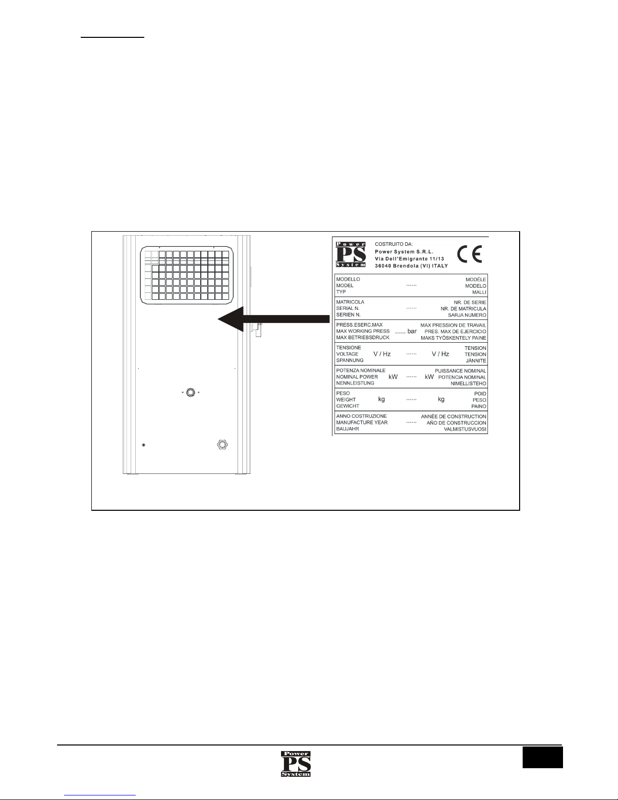
2.1 CE MARKING
The CE marking (FIG. 1) certifies the conformity of the compressor with the essential safety and health requirements contemplated by
the European Directives listed in the EC declaration of conformity.
It is an adhesive label made of silver coloured polyester with printing in black, with the following dimensions: L = 95 mm - H= 120
mm. It is applied on the outside, on the rear of the compressor. The following data are indicated legibly and indelibly on the plate:
• The logo, name and address of the manufacturer
• The CE mark
• The model
• The serial number
• The max. working pressure (bar)
• The voltage and frequency of the electric power supply (V / Hz)
• The nominal power (kW)
• The weight (kg)
• The year of manufacture
Left side
Fig.1 (CE marking)
Istruzioni per l’uso e manutenzione
Cod. OQ7.5ARG114 – GB
Emiss. 19-01-11 Rev. 0 - Agg. /
10
POWER SYSTEM SRL
Via dell’Emigrante, 11/13 - 36040 Brendola (VI) Italia
3 IMPORTANCE OF THE MANUAL
BEFORE USING THE COMPRESSOR THE AUTHORISED OPERATORS MUST READ AND
UNDERSTAND ALL PARTS OF THIS MANUAL.
This technical manual of “Instructions for use and maintenance” has been drawn up according to the indications given by the European
Directives, in order to ensure easy and correct understanding of the topics dealt with by the operators authorised to perform the use
and maintenance of the compressor concerned. If, despite the care taken by the manufacturer when drawing up the manual, these
operators find any problem in understanding it, in order to avoid incorrect personal interpretations that might endanger safety, they are
requested to apply promptly to the manufacturer for the correct explanations and any further information.
Before using the compressor, the authorised operators must read and understand all parts of this technical manual of “Instructions for
use and maintenance” and strictly follow all the rules in it, in order to ensure their own safety and that of other people, obtain the best
compressor performance, and ensure the maximum efficiency and long life of all its components. This manual must be at the disposal
of the authorised operators at all times and must always be kept safely, near the compressor.
THIS MANUAL MUST ALWAYS BE AT THE DISPOSAL OF THE AUTHORISED OPERATORS AND
MUST BE KEPT SAFELY, NEAR THE COMPRESSOR.
THE MANUFACTURER DECLINES ALL RESPONSIBILITY FOR ANY DAMAGE TO PERSONS,
ANIMALS AND THINGS RESULTING FROM FAILURE TO OBSERVE THE RULES AND WARNINGS
DESCRIBED IN THIS MANUAL.
THIS MANUAL MUST BE HANDED OVER TOGETHER WITH THE COMPRESSOR IF IT IS
TRANSFERRED TO ANOTHER USER.
THIS MANUAL REFLECTS THE STATE OF THE ART AT THE TIME THE COMPRESSOR WAS SOLD
AND CANNOT BE CONSIDERED INADEQUATE ONLY BECAUSE IT MAY BE UPDATED LATER IN
THE LIGHT OF NEW EXPERIENCE.
IF THE MANUAL IS LOST OR SPOILT, ASK THE MANUFACTURER FOR A NEW COPY, SPECIFYING
THE COMPRESSOR IDENTIFICATION DATA (SEE CE MARKING) AND THE REVISION.
3.1 NOTES FOR CONSULTATION
THE GENERAL DANGER SIGNAL AND THE FRAMED TEXT IN CAPITAL LETTERS DRAW THE
OPERATOR’S ATTENTION TO THE WARNINGS GIVEN IN THIS MANUAL.
N.B. (Nota Bene): framed text in capital letters.
Bold print: Highlights some significant sentences in the text.
Italics: Describes the captions of the figures and tables.
Istruzioni per l’uso e manutenzione
Cod. OQ7.5ARG114 – GB
Emiss. 19-01-11 Rev. 0 - Agg. /
11
POWER SYSTEM SRL
Via dell’Emigrante, 11/13 - 36040 Brendola (VI) Itali
a
3.2 INTENDED RECEIVERS (AUTHORISED OPERATORS)
This technical manual is intended exclusively for the operators authorised to carry out use and maintenance of the compressor,
according to the specific technical and professional skills required for the type of activity. The symbols shown below placed at the
beginning of a chapter and/or of a paragraph indicate which operator is involved in the subject dealt with.
THE AUTHORISED OPERATORS MUST PERFORM ON THE COMPRESSOR ONLY THE ACTIVITIES
FOR WHICH THEY ARE SPECIFICALLY COMPETENT.
BEFORE CARRYING OUT ANY ACTIVITY ON THE COMPRESSOR, THE AUTHORISED OPERATORS
MUST ENSURE THAT THEY ARE IN FULL POSSESSION OF THEIR PHYSICAL AND MENTAL
FACULTIES IN ORDER TO ENSURE THAT THE SAFETY CONDITIONS ARE ALWAYS RESPECTED.
GENERAL OPERATOR
This is a professionally trained operator, over 18 years of age, in compliance with the laws in force in the country of use,
authorised only to switch on, use, fine-tune (obligatorily with the guards enabled and the machine switched off) and
switch off the compressor, absolutely respecting the instructions given in this manual, provided with the personal
protective equipment (PPE) contemplated in table 7 and occupying the positions described in fig. 9.
HANDLING OPERATOR
This is a professionally trained operator, over 18 years of age, in compliance with the laws in force in the country of use,
authorised to use fork-lift trucks, bridge cranes or cranes, to transport and handle the compressor and/or its parts safely,
provided with the personal protective equipment (PPE) contemplated in table 7 and occupying the positions described in
fig. 9.
MECHANICAL / HYDRAULIC / PNEUMATIC OPERATOR
This is a qualified technician, approved to perform only operations on the mechanical / hydraulic / pneumatic parts to
carry out adjustments, maintenance and/or repairs even with the guards disabled (with the consent of the safety
manager), absolutely respecting the instructions given in this manual or any other specific document supplied
exclusively by the manufacturer, provided with the personal protective equipment (PPE) contemplated in table 7 and
occupying the positions described in fig. 9.
ELECTRICAL OPERATOR
This is a qualified technician (electrician in possession of the technical and professional skills required by the
regulations in force), approved to perform only operations on electric devices to carry out adjustments, maintenance
and/or repairs even with the system live and with the guards disabled (with the consent of the safety manager),
absolutely respecting the instructions given in this manual or any other specific document supplied exclusively by the
manufacturer, provided with the personal protective equipment (PPE) contemplated in table 7 and occupying the
positions described in fig. 9.
COMPANY SAFETY MANAGER
This is a qualified technician designated by the Customer, in possession of the technical and professional skills required
by the regulations in force concerning the safety and health of workers in the place of work.
Istruzioni per l’uso e manutenzione
Cod. OQ7.5ARG114 – GB
Emiss. 19-01-11 Rev. 0 - Agg. /
12
POWER SYSTEM SRL
Via dell’Emigrante, 11/13 - 36040 Brendola (VI) Italia
MANUFACTURER’S TECHNICIAN
This is a qualified technician made available by the Manufacturer and/or by the authorised Dealer to carry out the
requested technical assistance, routine and special maintenance jobs and/or operations not listed in this manual which
require a specific knowledge of the compressor, provided with the personal protective equipment (PPE) contemplated in
table 7 and occupying the positions described in fig. 9.
In the manual you can also find, next to a table, a figure, or a text, a double line “║“; this indicates the parts of the manual that have
been varied with respect to the previous revision.
3.3 MACHINE OFF STATUS
It is obligatory to disconnect the supply of electric power before carrying out any kind of maintenance work and/or
adjustment on the compressor.
1) Main electric switch turned “OFF” and padlocked;
2) Electric power supply switch (Customer) turned “OFF”;
3) Pressurised air discharged from the compressor (see pressure gauge on compressor).
4) Reservoir air outlet valve closed.
3.4 ABBREVIATIONS
TAB. 1 lists some abbreviations used in the text of the “instructions for use and maintenance”.
appro
x.
Approximately
min
Minutes
chap.
Chapter
No.
Number
PPE
Personal Protective Equipment
page
Page
Right
Right
par.
Paragraph
h
Hours
Pos.
Position
EN
European Norm
REF.
Reference
e.g.
Example
s
Seconds
FIG.
Figure(s)
Left
Left
max.
Maximum
TAB.
Table
min.
Minimum
see
See
3.5 RESERVED RIGHTS
All information (text, drawings, diagrams, etc.) given here is reserved. No part of this manual may be reproduced and made known
(completely or in part) with any means of reproduction (photocopies, microfilm or other) without the Manufacturer’s authorisation in
writing.
All the trade marks mentioned belong to their respective owners.
Istruzioni per l’uso e manutenzione
Cod. OQ7.5ARG114 – GB
Emiss. 19-01-11 Rev. 0 - Agg. /
13
POWER SYSTEM SRL
Via dell’Emigrante, 11/13 - 36040 Brendola (VI) Itali
a
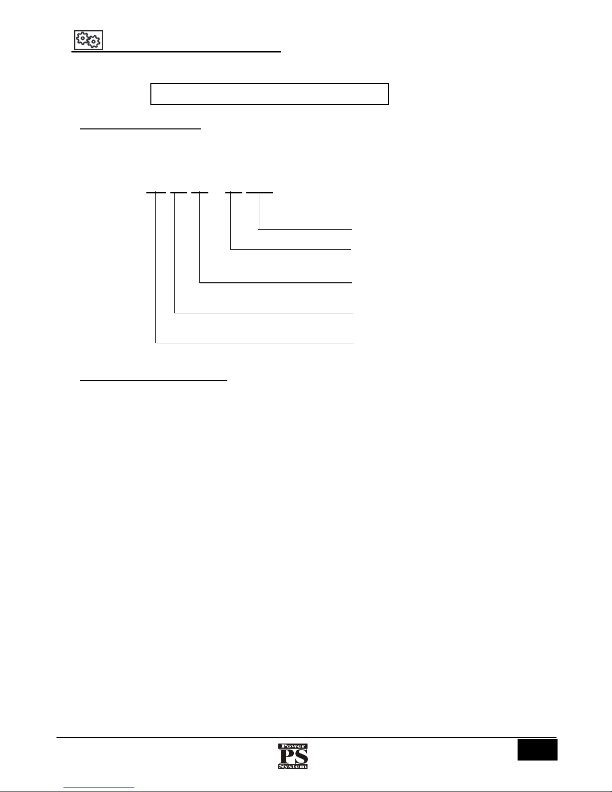
4 NAMING OF THE COMPRESSOR
The name of the compressor is:
4.1 NAMING OF THE MODELS
The models are named according to the motor power.
Name example:
PS 20 30 – 10 PM
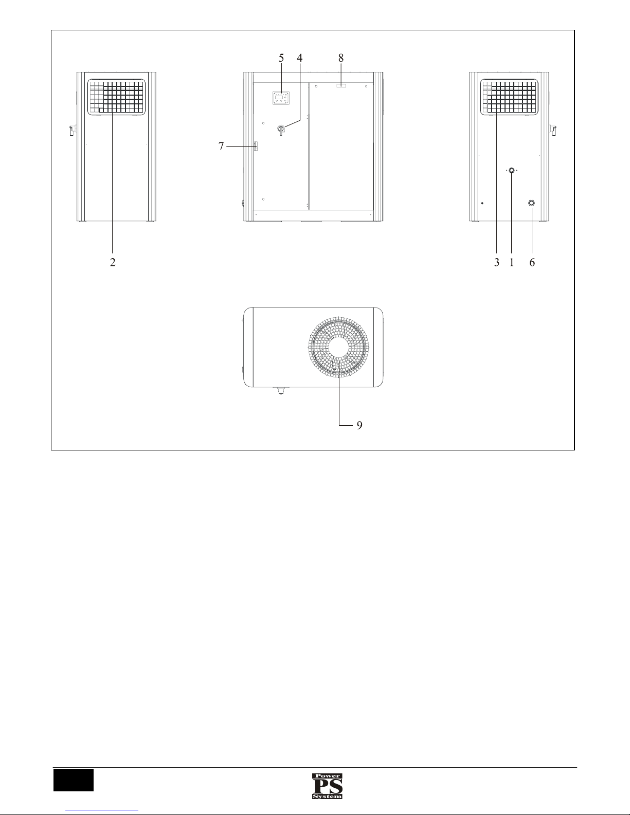
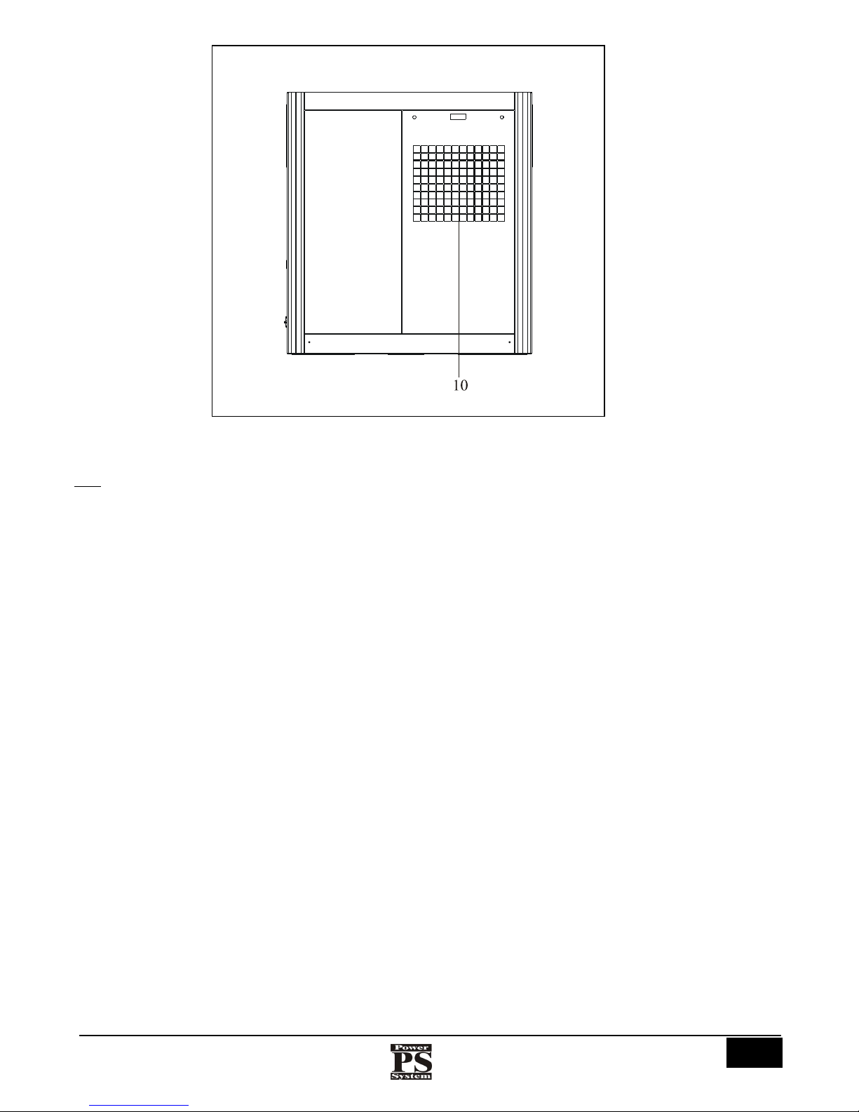
4.2 NAMING OF THE COMPONENTS
FIG. 2 and 3 show and name the main components of the compressors listed above.
ROTARY SCREW COMPRESSOR
Pressure (7,5 – 10 – 13 )
Power S
y
stem
Power (kW)
Compressor series
Series PM (Permanent Magnet)
Istruzioni per l’uso e manutenzione
Cod. OQ7.5ARG114 – GB
Emiss. 19-01-11 Rev. 0 - Agg. /
14
POWER SYSTEM SRL
Via dell’Emigrante, 11/13 - 36040 Brendola (VI) Italia
Fig.2
Left side
Right side
Fron
t
Overhead view
Istruzioni per l’uso e manutenzione
Cod. OQ7.5ARG114 – GB
Emiss. 19-01-11 Rev. 0 - Agg. /
15
POWER SYSTEM SRL
Via dell’Emigrante, 11/13 - 36040 Brendola (VI) Itali
a
Key:
1) Air output
2) Left side intake prefilter
3) Right side intake prefilter
4) Isolating switch
5) Control board
6) Cable entry
7) Front panel handle
8) Front panel handle
9) Electric fans
10) Dryer cooling air expulsion (if present)
Fig.3
Rear
Istruzioni per l’uso e manutenzione
Cod. OQ7.5ARG114 – GB
Emiss. 19-01-11 Rev. 0 - Agg. /
16
POWER SYSTEM SRL
Via dell’Emigrante, 11/13 - 36040 Brendola (VI) Italia
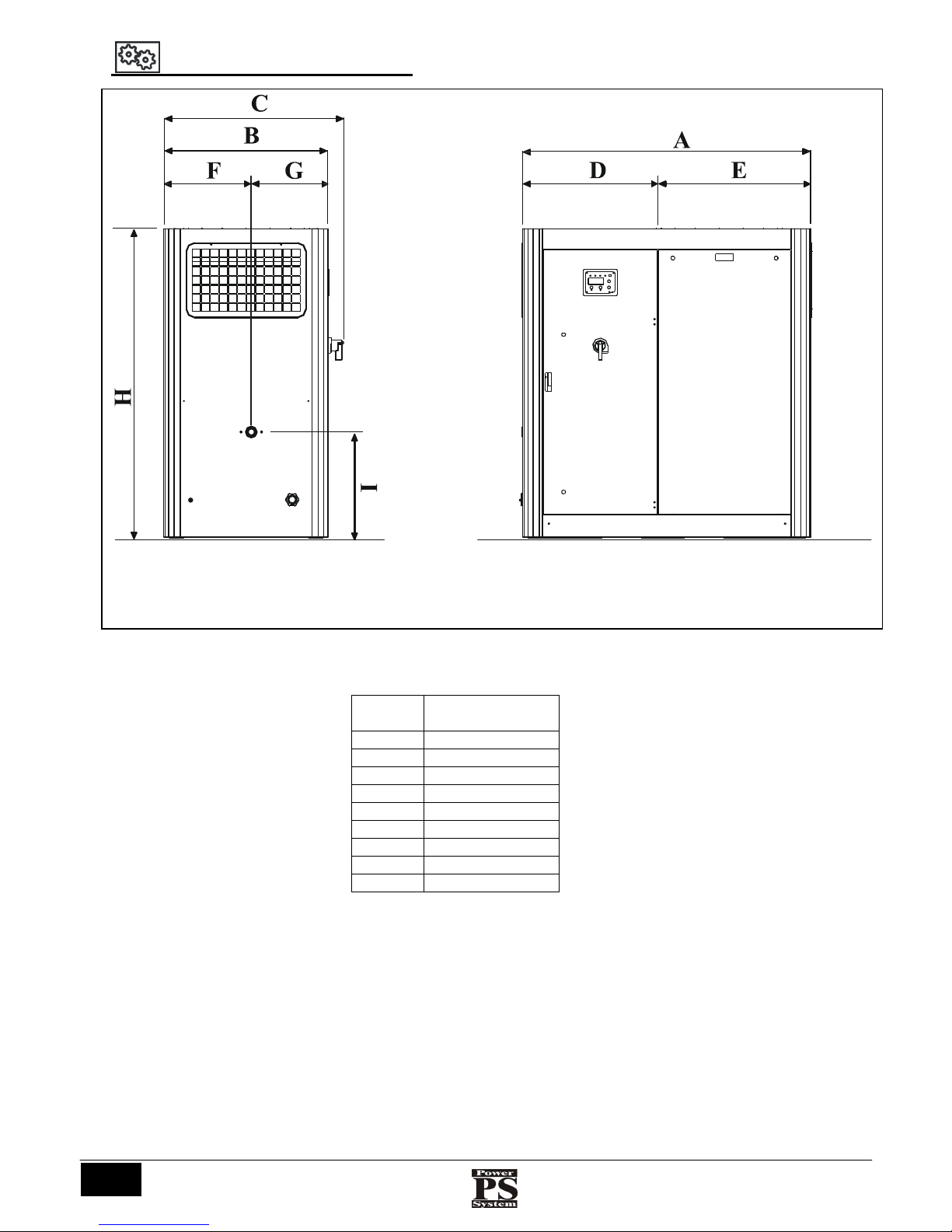
5 OVERALL DIMENSIONS (mm)
МОD. PS 2000
A 1400
B 800
C 875
D 660
E 745
F 425
G 375
H 1500
I 515
Fig.4
Front
Left side
Istruzioni per l’uso e manutenzione
Cod. OQ7.5ARG114 – GB
Emiss. 19-01-11 Rev. 0 - Agg. /
17
POWER SYSTEM SRL
Via dell’Emigrante, 11/13 - 36040 Brendola (VI) Itali
a
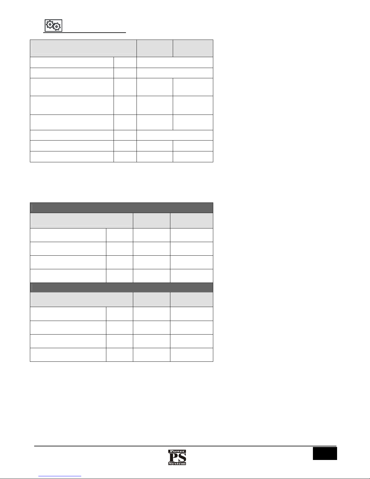
6 TECHNICAL DATA
* : without packaging
TAB.2
МОДЕЛЬ
PS2030DV PS2037DV
Max. delivery temperature
°C
110
Intake air temperature
°C
MIN
. 0° - MAX. 40°
Motor power / service factor
kW/Hp
30 (41)
FS1.15
37 (51)
FS1.15
Fan motor power
400V/50 Hz
W
790 790
Fan motor speed
400V/50 Hz
rpm
1310 1310
Noise
dB (A)
69
Compressor weight *
kg
550 570
Compressor weight with dryer *
kg
600 620
8 bar
Mod.
PS2030PM PS2037PM
Type of drive
400V/50 Hz
Direct
Direct
Delivery pressure
bar
min. 4 -
max. 11
min. 4 - max.
11
Full load current
400V/50 Hz
A
55 66
Compressor motor speed
400V/50 Hz
giri/min
Variable
800 ÷ 5500
Variable
800 ÷ 3700
10 bar
Mod.
PS2030PM PS2037PM
Type of drive
400V/50 Hz
Direct Direct
Delivery pressure
bar
min. 4 max. 11
min. 4 - max.
11
Full load current
400V/50 Hz
A
55 66
Compressor motor speed
400V/50 Hz
giri/min
Variable
800 ÷ 4900
Variable
900 ÷ 5500

Istruzioni per l’uso e manutenzione
Cod. OQ7.5ARG114 – GB
Emiss. 19-01-11 Rev. 0 - Agg. /
18
POWER SYSTEM SRL
Via dell’Emigrante, 11/13 - 36040 Brendola (VI) Italia
7 INTENDED USE
The compressor has been designed and made for the following intended use:
FIELD OF USE
Industrial and handicrafts sector
PLACE OF USE
In a closed, covered environment, sufficiently lit, suitable for the
legal requirements in force in the country of use concerning
safety and health in the work place. The compressor must stand
on a horizontal plane (level) which ensures its stability in
relation to its overall dimensions.
INTENDED USE
Compression of air for the use of suitable pneumatic tools
complying with the regulations in force (e.g.: guns for blowing,
washing, painting or sandblasting, screwdrivers, stapling guns,
nailing guns or grease guns).
GENERAL OPERATOR
Only one general operator in possession of the requirements
described above (chap. 3.2).
TAB.3
7.1 ENERGY SUPPLY SOURCES
ENERGY SOURCE SUPPLIES
ELECTRIC
Control panel (400/50)
TAB.4
7.2 STAGES OF USE
1) Connection of the air output pipe
2) Electric connection
3) Switching on
4) Production of compressed air
5) Switching off
6) Discharge of the residual air in the reservoir
7) Drainage of condensate from the reservoir
7.3 LIMITS OF USE
The compressor has been designed and made exclusively for the intended use described in table 3, so any other type of use is
absolutely forbidden, in order to guarantee, at all times, the safety of the operator and the efficiency of the compressor itself.
LIMITS OF USE: IT IS ABSOLUTELY FORBIDDEN TO USE THE COMPRESSOR FOR IMPROPER
APPLICATIONS, OTHER THAN THE USE INTENDED BY THE MANUFACTURER (TAB.3).
IT IS ABSOLUTELY FORBIDDEN TO START THE COMPRESSOR IN ENVIRONMENTS WITH A
POTENTIALLY EXPLOSIVE ATMOSPHERE AND/OR IN THE PRESENCE OF COMBUSTIBLE
POWDERS (E.G.: WOOD POWDER, FLOUR, SUGAR AND GRAIN).
IT IS ABSOLUTELY FORBIDDEN TO POINT JETS OF COMPRESSED AIR TOWARDS PERSONS,
ANIMALS AND THINGS
IT IS ABSOLUTELY FORBIDDEN TO USE AIR PIPES AND COUPLINGS THAT ARE NOT SUITABLE
AND/OR THAT DO NOT COMPLY WITH THE REGULATIONS IN FORCE.
DURING USE IT IS OBLIGATORY TO BE CONSTANTLY ON GUARD THAT NO UNAUTHORISED
PERSONS GO NEAR THE COMPRESSOR.
IT IS OBLIGATORY TO ANCHOR THE COMPRESSOR BY SECURING IT TO THE GROUND WITH
SCREWS SUITABLE FOR THE PURPOSE.

Istruzioni per l’uso e manutenzione
Cod. OQ7.5ARG114 – GB
Emiss. 19-01-11 Rev. 0 - Agg. /
19
POWER SYSTEM SRL
Via dell’Emigrante, 11/13 - 36040 Brendola (VI) Itali
a
7.4 OPTIONAL ACCESSORIES
THE ACCESSORIES MUST BE REQUESTED EXCLUSIVELY FROM THE MANUFACTURER,
COMMUNICATING THE SERIAL NUMBER AND THE YEAR OF MANUFACTURE OF THE
COMPRESSOR.
The accessories avalaible upon request for the PS2000PM models are the following:
- integrated dryer
- oil tank heating resistance
- heat recovery kit with oil/water heat exchanger
- triple stage air filter for dusty ambients
- tropicalized version
Please contact Power System for further
8 TRANSPORT OF THE COMPRESSOR
The compressor is delivered to the buyer by a carrier appointed by the customer, by the manufacturer or by the
authorised dealer, according to the contractual agreements at the time of sale.
8.1 PACKAGING
The compressor may be supplied alone, with a dryer, with a reservoir, or complete with dryer and reservoir.
The packaging may therefore be of different sizes. The cardboard packaging that covers the compressor and any accessories is marked
on the outside with one or more adhesive labels with the respective information.
ENSURE THAT THE PACKAGING HAS NOT BEEN DAMAGED DURING TRANSPORT.
MAKE A NOTE OF ANY DAMAGE FOUND ON THE DELIVERY NOTE AND SIGN IT STATING
“ACCEPTED WITH RESERVE”.

Istruzioni per l’uso e manutenzione
Cod. OQ7.5ARG114 – GB
Emiss. 19-01-11 Rev. 0 - Agg. /
20
POWER SYSTEM SRL
Via dell’Emigrante, 11/13 - 36040 Brendola (VI) Italia
9 UNPACKING AND HANDLING
The compressor should be lifted only with a pallet truck or a fork lift truck with suitable lifting capacity.
• Check the integrity of the packaging.
• Unpack the machine (paying attention to any indications on the packaging).
• Check the (outer) good condition of the machine.
• Open the access doors and check all inner parts (visual check).
• Dispose of the packing in compliance with the current waste disposal regulations.
IF ANY FAULTS ARE FOUND IT IS FORBIDDEN TO USE THE COMPRESSOR. YOU MUST APPLY TO
YOUR DEALER OR TO THE MANUFACTURER FOR TECHNICAL ASSISTANCE.
IT IS RECOMMENDED TO DISPOSE OF THE PACKAGING ACCORDING TO THE DIFFERENT TYPES
OF MATERIAL, ABSOLUTELY RESPECTING THE LAWS IN FORCE IN THE COUNTRY OF USE.
THE MACHINE PACKAGING MUST BE LIFTED WITH A FORK-LIFT TRUCK (SUITABLE FOR THE
USE), RESPECTING THE INSTRUCTIONS APPLIED ON THE OUTSIDE OF THE PACKAGING.
Proceed as follows:
1) Open and remove the cardboard using a suitable tool
2) Remove any screws securing the compressor to the pallet
3) Get into position on the longest side and insert the forks of the suitable fork-lift truck under the compressor or the reservoir,
until they come out on the opposite side.
4) Carefully lift the load and carry it to the place of use.
5) Lower the load very carefully until it is completely resting on the ground.
6) Extract the forks of the fork-lift truck from under the compressor or reservoir.
9.1 LIFTING AND HANDLING THE MACHINE
The compressor must be transported and handled only as shown in the following figure, with a pallet truck or a fork lift truck.
LIFT THE COMPRESSOR ONLY BY THE BASE; DO NOT TRY TO LIFT IT BY OTHER PARTS SUCH
AS THE CANOPY, MOTOR, PIPES AND SO ON.
PROTECT THE COMPRESSOR CANOPY WITH A CARDBOARD BOX
Fig.5

Istruzioni per l’uso e manutenzione
Cod. OQ7.5ARG114 – GB
Emiss. 19-01-11 Rev. 0 - Agg. /
21
POWER SYSTEM SRL
Via dell’Emigrante, 11/13 - 36040 Brendola (VI) Itali
a
10 INSTALLATION
The dimensions in the figure are in mm.
Key fig. 6:
1) Auxiliary reservoir condensate drain
2) Auxiliary reservoir (customer)
3) Compressor
4) Air expulsion
5) Main electric switch
6) Air intake
7) Electric power supply duct
8) Pneumatic system connecting pipe
Fig.6
Overhead view
View A-A

Istruzioni per l’uso e manutenzione
Cod. OQ7.5ARG114 – GB
Emiss. 19-01-11 Rev. 0 - Agg. /
22
POWER SYSTEM SRL
Via dell’Emigrante, 11/13 - 36040 Brendola (VI) Italia
10.1 GENERAL WARNINGS
IT IS ABSOLUTELY FORBIDDEN TO USE AIR PIPES AND COUPLINGS THAT ARE NOT
SUITABLE AND/OR DO NOT COMPLY WITH THE REGULATIONS IN FORCE.
DURING COMPRESSOR OPERATION IT IS FORBIDDEN TO DISCONNECT THE
PRESSURISED AIR PIPES. THERE IS A RESIDUAL RISK.
IT IS OBLIGATORY TO INSTALL THE COMPRESSOR IN A PLACE WITH ADEQUATE
VENTILATION WHICH ENABLES THE AMBIENT TEMPERATURE TO BE MAINTAINED
BETWEEN +2 °C AND +40 °C, WITH HUMIDITY BETWEEN 5 AND 95%.
IT IS OBLIGATORY TO CONTACT THE MANUFACTURER OR AUTHORISED DEALER IN
THE EVENT OF AN INADEQUATE OUTPUT OF HOT AIR FROM THE PLACE IN WHICH THE
COMPRESSOR IS INSTALLED.
THE AIR SENT INTO THE PLACE WHERE THE COMPRESSOR IS INSTALLED MUST BE
CLEAN AND FREE FROM DUST, FUMES AND INFLAMMABLE VAPOURS.
10.2 POSITIONING
The compressor must be positioned in the place of installation and use in conformity with the provisions in the table of
“Technical data”.
IT IS OBLIGATORY TO ENSURE THE MINIMUM POSITIONING MEASUREMENTS GIVEN
IN FIG. 6.
IT IS OBLIGATORY TO SECURE THE COMPRESSOR TO THE GROUND WITH THE FEET
PROVIDED, USING SCREWS SUITABLE FOR THE PURPOSE.
TO ENSURE THAT THE AUTHORISED OPERATORS ARE ABLE TO OCCUPY THE WORK PLACES
CONTEMPLATED IN FIG. 11, IT IS OBLIGATORY TO RESPECT THE MINIMUM POSITIONING
MEASUREMENTS GIVEN IN FIG. 6.
10.3 SECURING THE COMPRESSOR AND CONNECTING THE AIR PIPE
After having respected the minimum positioning measurements given in FIG. 6 it is necessary to anchor
the feet to the floor with screws suitable for the purpose.
After having positioned and secured the compressor correctly, proceed as follows:
1) Connect the pipe to the air output fitting on the compressor (FIG. 6 - Ref. 8);
2) Connect the pipe to the air input fitting of the pneumatic system (FIG. 6 - Ref. 8).
10.4 TEMPERATURE BELOW 0° C
1. Ensure that the control lines, the drains and the siphons are heated so as to avoid freezing of the condensate.
2. A simple roof must be provided in case of rain or snow.
3. Use only oil suitable for low temperatures (consult Power System).

Istruzioni per l’uso e manutenzione
Cod. OQ7.5ARG114 – GB
Emiss. 19-01-11 Rev. 0 - Agg. /
23
POWER SYSTEM SRL
Via dell’Emigrante, 11/13 - 36040 Brendola (VI) Itali
a
10.5 AIR TANK
An auxiliary air tank is always required if the pipe system is not very long, so as to have a sufficient storage capacity and thus avoid
rapid cycles. The air tank must be provided with a safety valve, a suitable pressure gauge and a system for draining condensate.
IF AN AIR STORAGE TANK OUTSIDE THE COMPRESSOR IS USED, DO NOT FIT CHECK VALVES
BETWEEN THE COMPRESSOR AND THE TANK.
10.6 CONDENSATE SEPARATOR
The machine is equipped with its own final compressed air cooler and with a condensate separator with automatic drainage. Where
this device is not a standard feature it is possible to have it as an option.
CONDENSATE IS A POLLUTING MIXTURE AND MUST NOT BE SCATTERED IN THE
ENVIRONMENT OR IN THE SEWER NETWORK. THE PIT MUST BE PROVIDED WITH A VALVE AND
A REMOVABLE CONTAINER OR CONNECTED TO SPECIAL EQUIPMENT.
10.7 DISTRIBUTION LINE
A good distribution network must provide:
1- slope of about 1% so that any condensate can be collected in the lowest points;
2- junctions for branches in the upper part of the main pipe;
3- each junction must have a drain in the lowest point;
4- ball valves for sectioning the main pipe; drawing point with ball valves;
5- drawing point equipped with filters, oilers or safety filters, depending on the application.
Pay particular attention to continuous load losses along the pipe.
10.8 WARM AIR OUTLET CONVEYING
• Warm air comes out of the top of the compressor at a temperature of about 15-35°C higher than the environment temperature.
• If the ventilation of the premises is insufficient it will be indispensable to install a duct with a section the same size as the radiator
surface.
TO ENSURE AN EFFICIENT EXPULSION OF WARM AIR FROM THE MACHINE THESE CHANNELS
MUST NOT BE MORE THAN 3 METRES LONG; OTHERWISE IT IS NECESSARY TO INSTALL AN
AUXILIARY FAN ON THE OUTLET SIDE (FIG.7).
Fig.7

Istruzioni per l’uso e manutenzione
Cod. OQ7.5ARG114 – GB
Emiss. 19-01-11 Rev. 0 - Agg. /
24
POWER SYSTEM SRL
Via dell’Emigrante, 11/13 - 36040 Brendola (VI) Italia
11 ELECTRICAL CONNECTION
The electric power supply line must be made using cables with a suitable section (*) for the machine power and it must
include 3 phase cables + 1 earth cable.
• For models in which there is a dryer or a heating element, 1 neutral cable is also necessary.
• Compressors using a 220V power supply do not require a neutral cable.
• It is indispensable to install between the power supply line and the compressor control panel:
- either an automatic magnetothermal switch with appropriate circuit breaking capacity and operating
sensitivity curve “D”;
- or a disconnecting switch with suitable capacity equipped with delayed fuses, AM curve, for motor starting.
(To choose between a magnetothermal switch or a disconnecting switch with fuses, follow the instructions of the
regulations in force in the country of installation.)
• The switch must be within easy reach of the operator.
(*) For the section of the cables, follow the indications given in the “electric data table” in the manual.
The cables must be of an approved type, with a suitable degree of insulation.
THE ELECTRIC POWER MAINS TO WHICH THE COMPRESSOR IS CONNECTED MUST
SATISFY THE TECHNICAL CHARACTERISTICS GIVEN IN THE PREVIOUS TABLES AND COMPLY
WITH THE REQUIREMENTS CONTEMPLATED BY THE REGULATIONS IN FORCE IN THE
COUNTRY OF USE.
THE ELECTRICAL CONNECTION OF THE COMPRESSOR TO THE ELECTRIC POWER LINE
MUST BE CARRIED OUT BY A QUALIFIED ELECTRICIAN, IN POSSESSION OF THE TECHNICAL
AND PROFESSIONAL SKILLS REQUIRED BY THE REGULATIONS IN FORCE.
UPSTREAM FROM THE ELECTRIC POWER LINE IT IS OBLIGATORY TO INSTALL A SUITABLE
ISOLATING DEVICE WITH DIFFERENTIAL PROTECTION, COORDINATED WITH THE
EARTH SYSTEM.
THE MANUFACTURER DECLINES ALL RESPONSIBILITY FOR COMPRESSOR BREAKDOWNS OR
MALFUNCTIONS CAUSED BY SUDDEN CHANGES IN THE ELECTRIC VOLTAGE BEYOND THE
TOLERANCES CONTEMPLATED BY THE POWER DISTRIBUTION BOARD (VOLTAGE ±10%).
FAILURE TO RESPECT THE ABOVE WARNINGS MAY CAUSE IRREPARABLE DAMAGE TO THE
ELECTRICAL EQUIPMENT OF THE COMPRESSOR AND THE CONSEQUENT VOIDING
OF THE GUARANTEE.
THE MANUFACTURER DECLINES ALL RESPONSIBILITY FOR ANY DAMAGE CAUSED TO
PERSONS, ANIMALS AND/OR THINGS DUE TO THE INCORRECT ELECTRICAL CONNECTION OF
THE COMPRESSOR.
12 BEFORE FIRST STARTING
Before starting the compressor for the first time it is compulsory to ensure that:
• The incoming voltage is the same as indicated on the data plate
• All electrical connections have been made with cables of adequate size and type
• The main automatic switch (on the wall) is of the correct type and size.
• electrical connections are intact
• the internal pipes of the air / oil system are intact.
• Remove the yellow blocks necessary for transport (if present)

Istruzioni per l’uso e manutenzione
Cod. OQ7.5ARG114 – GB
Emiss. 19-01-11 Rev. 0 - Agg. /
25
POWER SYSTEM SRL
Via dell’Emigrante, 11/13 - 36040 Brendola (VI) Itali
a
13 FIRST START-UP
The first start-up of the compressor (operative test) must obligatorily be carried out by a specialized technician.
Ask the testing technician to fill in the R.C.R. form at the end of the manual. Filling in this form allows you to be sure that a complete
test has been performed and, in the event of malfunctions of any kind, faster and more effective action can be taken under guarantee.
Compressors with an inverter are equipped with an electronic system to control the absorbed power and the motor temperature, in
any case it is important to take the greatest care during the first start-up to avoid very serious damage to the compressor itself.
To make the first start-up, after installation, turn on the power supply to the electric panel, press the “Start” key and check that the
electric fan is turning in the correct direction, comparing it with the direction indicated by the sticker on the structure. If the direction
is incorrect, proceed as follows:
a) switch off the machine
b) switch off the power
c) exchange the connections of two phases of the electric fan power supply
d) restart the machine.
FOR THE FIRST START-UP CONSULT THE SPECIFIC INVERTER MANUAL SUPPLIED WITH THE
DOCUMENTATION.
To change the fuses and the electric cables, refer to the following table.
400/50
PS 2030 PM PS 2037 PM
Input cables minimum section (*) mm² 16 25
Electronic board fuses N° x A 1 x 2 1 x 2
Electric panel fuses N° x A
Check wiring diagram
Auxiliary / electronic panel voltage V 110 / 15 110 / 15
(*) Neutral connection if there is a dryer or heater present.

Istruzioni per l’uso e manutenzione
Cod. OQ7.5ARG114 – GB
Emiss. 19-01-11 Rev. 0 - Agg. /
26
POWER SYSTEM SRL
Via dell’Emigrante, 11/13 - 36040 Brendola (VI) Italia
14 STORAGE
If for various reasons the compressor cannot be installed at the time of delivery and has to remain some time in storage, it must be
placed in a safe environment, with an adequate temperature and degree of humidity, and protected against dust.
THE CUSTOMER (EMPLOYER) MUST TAKE ALL NECESSARY STEPS TO ENSURE THAT HIS
EMPLOYEES CANNOT ACCESS THE PLACE OF INSTALLATION OF THE COMPRESSOR FOR ANY
REASON UNTIL IT HAS BEEN TESTED.
IT IS FORBIDDEN TO SWITCH ON THE COMPRESSOR UNTIL THE INSPECTION CERTIFICATE
HAS BEEN SIGNED.
THE SIGNING OF THE INSPECTION CERTIFICATE CONFIRMS THE CORRECT OPERATION OF
THE COMPRESSOR AND THE ABSENCE OF ANY VISIBLE DEFECTS.
THE MANUFACTURER DECLINES ALL RESPONSIBILITY FOR ANY CLAIMS CONCERNING THE
OPERATION OF THE COMPRESSOR, COMMUNICATED BY THE CUSTOMER AFTER THE
INSPECTION HAS BEEN CARRIED OUT.
N.B.: A COPY OF THE INSPECTION CERTIFICATE, FULLY COMPILED AND SIGNED, MUST BE
GIVEN TO THE MANUFACTURER’S INSPECTION TECHNICIAN.

Istruzioni per l’uso e manutenzione
Cod. OQ7.5ARG114 – GB
Emiss. 19-01-11 Rev. 0 - Agg. /
27
POWER SYSTEM SRL
Via dell’Emigrante, 11/13 - 36040 Brendola (VI) Itali
a
15 DIRECTIVES AND REFERENCE NORMS
The compressor has been designed and made considering the assessments emerging from an accurate analysis of risks and aiming to
achieve, considering the present state of the art, the objectives established by the essential safety and health requirements contemplated
by the European Directives.
TAB. 5 lists the European Directives and Norms (EN) to which reference has been made.
REFERENCE DESCRIPTION
2006/42/EC
“Of the European Parliament and of the Council, of 17 May 2006, concerning
machinery and amending directive 95/16CE”.
2006/95/EC
“Low Voltage Directive - Of the European Parliament and of the Council of 12
December 2006 on the harmonisation of the laws of Member States relating to
Electrical Equipment designed for use within certain voltage limits”.
2004/108/EC
“Electromagnetic Compatibility Directive - Of the Council, of 15 December 2004,
on the approximation of the laws of the Member States relating to Electromagnetic
Compatibility and repealing Directive 89/336/EC”.
2009/105/CE
“Pressure Equipment Directive” 2009/105/EC - Of the European Parliament and of
the Council of 16 September 2009 relating to simple pressure vessels”
EN 1012-1 : 1997
“Compressors and vacuum pumps. Safety requirements. Compressors”.
EN 60204-1 : 2006
“Fundamental safety standards on the Electrical equipment of machines”.
TAB.5
16 SAFETY
IT IS FORBIDDEN TO TAMPER WITH, EXCLUDE, REMOVE AND/OR REPLACE ANY
SAFETY DEVICE PRESENT IN THE COMPRESSOR.
IT IS OBLIGATORY TO REQUEST THE INTERVENTION OF THE TECHNICAL ASSISTANCE OF
THE MANUFACTURER OR THE AUTHORISED DEALER FOR THE REPLACEMENT OF ANY
SAFETY DEVICE.
16.1 SAFETY SIGNALS
The signals are composed of yellow adhesive labels with black pictograms, applied on the front and rear of the compressor (see FIG.
8). The meaning of each signal is explained in TAB. 6.
IT IS OBLIGATORY TO KEEP THE SAFETY SIGNALS CLEAN TO ENSURE GOOD VISIBILITY.
IT IS ABSOLUTELY FORBIDDEN TO REMOVE AND/OR DAMAGE THE SAFETY SIGNALS APPLIED
BY THE MANUFACTURER.
IT IS OBLIGATORY TO REPLACE ANY DAMAGED SAFETY SIGNALS, ASKING THE
MANUFACTURER TO SUPPLY REPLACEMENTS.

Istruzioni per l’uso e manutenzione
Cod. OQ7.5ARG114 – GB
Emiss. 19-01-11 Rev. 0 - Agg. /
28
POWER SYSTEM SRL
Via dell’Emigrante, 11/13 - 36040 Brendola (VI) Italia
Fig.8

Istruzioni per l’uso e manutenzione
Cod. OQ7.5ARG114 – GB
Emiss. 19-01-11 Rev. 0 - Agg. /
29
POWER SYSTEM SRL
Via dell’Emigrante, 11/13 - 36040 Brendola (VI) Itali
a
RISKS
SIGNAL MEANING
GENERAL RISK
The compressor must work with the doors closed (five languages).
RISK OF ELECTRIC CURRENT
Inside the compressor and the electric panel.
RISK OF NOISE
During compressor operation the noise may reach dangerous levels for
your hearing.
RISK OF PRESSURISED RESERVOIR
The reservoir reaches dangerous pressure levels.
RISK OF CONTACT WITH THE COOLING FAN
When the protective doors are open there is the risk of contact with the
cooling fan.
RISK OF HIGH TEMPERATURE
There is the risk of burns in contact with hot parts.
RISK OF PRESSURISED AIR
Accidental malfunctions during the connection of the pipes and the
filling and discharging phase.
TAB.6

Istruzioni per l’uso e manutenzione
Cod. OQ7.5ARG114 – GB
Emiss. 19-01-11 Rev. 0 - Agg. /
30
POWER SYSTEM SRL
Via dell’Emigrante, 11/13 - 36040 Brendola (VI) Italia
16.2 RESIDUAL RISKS
We inform the authorised operators that, although the manufacturer has taken all the technical and constructive precautions possible to
make the compressor safe, there remain some potential residual risks described in TAB. 7.
RESIDUAL RISK
No.1
RISK OF BEING STRUCK BY PRESSURISED AIR AND/OR PIPES
FREQUENCY OF
EXPOSURE
Low and accidental. There may be exposure if the operator decides of his own accord to perform an
action that is incorrect, forbidden and not reasonably foreseeable.
EXTENT OF
DAMAGE
Slight injuries (normally reversible).
STEPS TAKEN
Respect of the correct procedure for connecting/disconnecting air pipes (see par. 10.3).
Safety signals (tab. 6).
TAB.7
16.3 AUTHORISED OPERATORS: PLACES OCCUPIED
Depending on the type of manual intervention required, the authorised operators must occupy exclusively the positions indicated in
fig. 9.
DEPENDING ON THE PLACES OCCUPIED, THE AUTHORISED OPERATORS MUST OBLIGATORILY
AND EXCLUSIVELY PERFORM THE MANUAL INTERVENTIONS DESCRIBED IN THE RESPECTIVE
PARAGRAPHS.
Fig.9
Overhead view
Left side
Right side
Main electric
switch
Front
Rear

Istruzioni per l’uso e manutenzione
Cod. OQ7.5ARG114 – GB
Emiss. 19-01-11 Rev. 0 - Agg. /
31
POWER SYSTEM SRL
Via dell’Emigrante, 11/13 - 36040 Brendola (VI) Itali
a
AUTHORISED
OPERATORS
POSITION DESCRIPTION OF INTERVENTION
ALL To perform all the operations of transporting and handling the machine (see chap. 8 - 9)
ALL
To carry out installation and the necessary maintenance operations, after consent from the
safety manager.
Standing at the front, facing the control panel, to perform:
1) Switching the control panel on/off with the main electric switch:
2) Setting the work parameters and viewing the machine status on the display;
3) Switching the compressor on/off with the buttons on the control panel.
Standing at the right side of the compressor to perform:
1) Opening/closing the valve on the compressor air outlet
Standing at the left side of the compressor to perform:
1) Activation of the main electric switch to isolate the electric power supply.
2) Maintenance of suction prefilter.
Standing at the rear of the compressor to perform:
1) Maintenance of suction prefilter.
TAB.8
B
A
C
D

Istruzioni per l’uso e manutenzione
Cod. OQ7.5ARG114 – GB
Emiss. 19-01-11 Rev. 0 - Agg. /
32
POWER SYSTEM SRL
Via dell’Emigrante, 11/13 - 36040 Brendola (VI) Italia
17 CONTROL PANEL FOR THE BOARD EPS4.3
RIF. DENOMINATION FUNCTION
1
Led green Rotating motor.
2
Led green Active loading electrovalve
3
Led green Oil heater operating.
4
Led yellow
Remote control enable
5
Led white
“AUTO RESTART”
Automatic restart enabled.
6
Blue “PROG” button
(Programming)
Pressing it once allows you to enter the programming parameters menu.
Pressing it again allows you to scroll through the various programming
menus. Holding it down on the desired menu allows you to change the
set parameters by pressing the “+” and “-” keys. Press it again to confirm
the change. To quit, hold down the key for a longer time. The system
quits programming automatically after 80 sec.
EPS4.
3
EPS4.
3
EPS4.
3
EPS4.3

Istruzioni per l’uso e manutenzione
Cod. OQ7.5ARG114 – GB
Emiss. 19-01-11 Rev. 0 - Agg. /
33
POWER SYSTEM SRL
Via dell’Emigrante, 11/13 - 36040 Brendola (VI) Itali
a
RIF. DENOMINATION FUNCTION
7
Main electric switch
“O - OFF” - “I - ON”
• Pos. “O - OFF”: Switches off power to the command and control
panel.
Pos. “I - ON”: Switches on power to the command and control panel.
8
Yellow button with danger signal,
clock “h” - “RESET”
Resets alarms
At the 1
st
click it shows information on the hours worked
At the 2
nd
click it shows the auxiliary temperature
9
Green “Start” button “I”, “-”
symbol
Allows the “Rotary test”
Allows starting of the compressor
If during programming decreases the values.
10
Led green Machine started
11
LCD alphanumeric display with 2
lines of 16 characters
Displays the video pages for setting the work parameters, the machine
status and the alarms (see par. 17.5).
12
Red “STOP” button, “+” symbol
Allows stopping of the compressor
If during programming increases the values
13
Led green Machine stopped

Istruzioni per l’uso e manutenzione
Cod. OQ7.5ARG114 – GB
Emiss. 19-01-11 Rev. 0 - Agg. /
34
POWER SYSTEM SRL
Via dell’Emigrante, 11/13 - 36040 Brendola (VI) Italia
17.1 SWITCHING ON THE BOARD AND STARTING THE COMPRESSOR
When the Start button is pressed the machine “STOP” status changes to “WAIT FOR START”, this is followed by the operation of the
compressor showing: “WAIT FOR LOAD”, “LOAD”.
Status indication
Outlet air pressure
Air/oil delivery
temperature
STOP
00bar 30°C
Press start button
Next
WAIT FOR START
00bar 30°C
WAIT FOR LOAD
00bar 30°C
LOAD
7.8bar 70°C

Istruzioni per l’uso e manutenzione
Cod. OQ7.5ARG114 – GB
Emiss. 19-01-11 Rev. 0 - Agg. /
35
POWER SYSTEM SRL
Via dell’Emigrante, 11/13 - 36040 Brendola (VI) Itali
a
17.2 ACCESS TO THE USER PROGRAMMING MENU
THE STORAGE OF ANY CHOSEN PARAMETER TAKES PLACE AFTER 60 SECONDS WITH THE
MACHINE TURNED ON.
To access the “User programming” menu and programme the electronic board, proceed as follows:
1. press the programming key
2. scroll through the screens by pressing the “PROG” key
3. hold down the “PROG” key until the parameter blinks
4. press the “+” or “-“ key to vary the parameter
5. confirm the variation by holding down the “PROG” key
6. scroll through the remaining parameters or quit programming by holding down the “PROG” key
The screens shown in sequence, with the possibility of changing the parameter, are listed below:
LCD RANGE
DEFAULT COMMENT
1
LANGUAGE
ENGLISH
LANGUAGE OF THE COUNTRY
OF DESTINATION
SET CHOSEN LANGUAGE
2
ROTARY TEST
STOP (*)
/
CHECK THE DIRECTION OF
ROTATION OF THE ELECTRIC
FAN
3
ROTARY TEST
START (*)
/
CHECK THE DIRECTION OF
ROTATION OF THE ELECTRIC
FAN
4
PRESSURE SET
7,5 bar
2 ÷ 15 bar
WORKING PRESSURE VALUE SELECT SET PRESSURE
5
LOAD PRESS. GAP
1,5 bar
0,2 ÷ 3 bar
1 bar
SELECT THE PRESSURE RANGE
IN WHICH THE MACHINE
WORKS
6
HISTORY ALARM
/
ALARM HISTORY: STORES THE
LAST 16 ALARMS
7
CONDENSATE DRAIN
300 sec.
0 ÷ 999 s
300 sec
SELECT TIME INTERVAL
BETWEEN ONE CONDENSATE
DRAINAGE AND THE NEXT
8
CONDENSATE DRAIN
LOAD ONLY
LOAD ONLY
SELECT CONDENSATE
DRAINAGE METHOD
9
CONDENSATE DRAIN
ALWAYS
/ /
10
MACHINE STARTING
LOCAL
LOCAL
SELECT MACHINE START
METHOD
11
MACHINE STARTING
AUTO RESTART
/
SELECT MACHINE START
METHOD
12
MACHINE STARTING
REMOTE CONTROL
/
SELECT MACHINE START
METHOD
13
STAND-BY TIME
120 sec.
30 ÷ 600 s
120 sec SELECT STAND-BY TIME
14
MACHINE STATUS
MOTOR STATUS
MOTOR STATUS
REAL MACHINE STATUS.
CHANGES THE CONTACT WITH
THE MOTOR TURNING
15
MACHINE STATUS
ALARMS INDICATOR
CHANGES THE CONTACT IN
THE PRESENCE OF AN ALARM
16
MACHINE STATUS
RUN INDICATOR
CHANGES THE CONTACT WITH
MACHINE ON OR IN STAND BY
17
INSERT CODE DATA
0
0 See Chap. 18.
After 80 seconds the system quits programming automatically
(*) Screen shown only when the machine is stopped.
17.3 ACCESS TO THE SERVICE PROGRAMMING MENU (Password required)
Contact Power System
17.4 CHECKING AND SETTING THE SECOND TEMPERATURE PROBE (Password required)
Contact Power System

Istruzioni per l’uso e manutenzione
Cod. OQ7.5ARG114 – GB
Emiss. 19-01-11 Rev. 0 - Agg. /
36
POWER SYSTEM SRL
Via dell’Emigrante, 11/13 - 36040 Brendola (VI) Italia
17.5 EPS4.2 TROUBLESHOOTING
N. Allarm
Alarm messages Cause Explanation / Remedies
1
Low temperature
Oil temperature below the
programmable fixed limit
The compressor does not start but stores the start order in the
memory. When the min. set temperature is reached for
external causes, the compressor starts automatically. The
message “T out of scale” appears in the alarm log.
• Check heater connection, if present.
• Install heater.
2
High temperature
Oil temperature above the
programmable fixed limit
The compressor stops and consequently the oil cools. When
the oil temp. falls below the set limit, the compressor does
not start (it must be restarted) and the message “High oil
temp.” becomes “Temp. out of scale”. The message “T out
of scale” appears in the alarm log.
• Check the causes of the faulty heat exchange; if the
reading does not agree with the temperature change
the probe.
H = NTC short
circuiting.
3
NTC broken
L = NTC interrupted or
disconnected
Connect or replace
4
(1)
Active emergency
The mushroom switch has
been activated
Release the emergency switch by turning it..
5
Motor thermal
prot
The thermal relay of the
main motor has tripped.
If it does not have automatic reset, reset the thermal relay. Press
the reset key. Check the absorbed current values and the
calibration value.
6
Inverter blocked
The inverter has generated
an alarm
Read the fault indicated on the inverter display. Follow the
instructions in the inverter manual.
7
Fan thermal prot
The fan motor protector
has tripped.
Reset the contact, press the key on the board. Check the current
values and the calibration value.
8
(2)
Incorrect rotation
The electric connection
would make the
compressor turn in the
opposite direction,
damaging it
Switch off the power and invert 2 of the 3 phases.
9
Default data
/ Contact Power System
L = Pressure transmitter
disconnected.
10
TRD broken
H = Pressure transmitter
short circuiting.
Check the connection to the transmitter.
Change transmitter.
11
Maint Group A
The machine has
reached the set number
of working hours to
carry out maintenance of
the Group A, follow the
instructions on the
display
Carry out maintenance and hold down the Reset key for at
least 30 sec.

Istruzioni per l’uso e manutenzione
Cod. OQ7.5ARG114 – GB
Emiss. 19-01-11 Rev. 0 - Agg. /
37
POWER SYSTEM SRL
Via dell’Emigrante, 11/13 - 36040 Brendola (VI) Itali
a
12
Maint Group B
The machine has reached
the set number of working
hours to carry out
maintenance of the Group
B, follow the instructions
on the display
Carry out maintenance and hold down the Reset key for at least
30 sec.
13
System alarm 65
/ Contact Power System
14
Temp. Alarm 2
The auxiliary temperature
probe measures a value
higher than the set
threshold. The machine
stops. Warning message is
displayed.
Contact Power System
H = NTC 2 short circuiting
15
NTC 2 broken
L = NTC 2 interrupted
or disconnected
Connect or replace
16
High pressure
High pressure in the
system The machine
stops.
Check the intake valve, pressure switch and pressure sensor..
(1)
If present.
(2
)
If the phase control is present. (Check wiring diagram)
N.B. Once you have removed the cause of the fault you must press the “RESET” key
17.6 FUNCTION OF THE RESET KEY
The “RESET” key allows the elimination of any alarms present.
When the “RESET” key is pressed only once, when the machine is not in alarm status, the machine’s total operating and loading hours
are displayed.
When the “RESET” key is pressed the second time, the temperature detected by the second probe is displayed.
When the “RESET” key is pressed the third time, the countdown time to the following maintenance operations:
Total 0:0
Load 0:0
Machine’s loading
operating hours
Machine’s total
operating hours
TEMPERATURE -2-
Probe Not Present
Probe disconnected / absent
TEMPERATURE -2-
10.5°C
Probe present: displays
temperature detected
1999 HH -A-
3999
HH -B-
Countdown hours to
maintenance –B-
Countdown hours to
maintenance –A-

Istruzioni per l’uso e manutenzione
Cod. OQ7.5ARG114 – GB
Emiss. 19-01-11 Rev. 0 - Agg. /
38
POWER SYSTEM SRL
Via dell’Emigrante, 11/13 - 36040 Brendola (VI) Italia
17.7 MACHINE STATUS
The machine status function is accomplished by means of a dry contact relay located on the power board.
To use this switching contact you must operate directly on the terminal board in the electric panel on the terminals C (common), NO
(normally open) and NC (normally closed); see fig.A ref.1.
The activation of this relay may influence running status, alarm status or motor rotation. These 3 functions are selected in the “User
programming” parameters, ref.14 – 15 – 16.
17.8 HEATING ELEMENT
If present, the heating element is positioned in the separator tank ( fig.B ref.A) and, when the temperature is below 10°C, it starts up to
heat the oil. The temperature is detected by the oil probe.
The heating resistance (max. 125W) is connected to the terminals indicated in fig.A ref.2.
1
Fig. A
1 1
2 2
1 2
2
Fig. B
A

Istruzioni per l’uso e manutenzione
Cod. OQ7.5ARG114 – GB
Emiss. 19-01-11 Rev. 0 - Agg. /
39
POWER SYSTEM SRL
Via dell’Emigrante, 11/13 - 36040 Brendola (VI) Itali
a
18 CHECKS BEFORE SWITCHING ON
BEFORE SWITCHING ON THE COMPRESSOR THE AUTHORISED OPERATORS MUST PERFORM
THE CHECKS LISTED IN TAB. 9.
IT IS ABSOLUTELY FORBIDDEN TO SWITCH ON THE COMPRESSOR IF ANY DAMAGE AND/OR
ABNORMAL SITUATION IS FOUND. IF NECESSARY, ASK FOR THE MANUFACTURER’S
INTERVENTION AND NOTIFY THE COMPANY SAFETY MANAGER.
1
ENSURE THAT THERE ARE NO UNAUTHORISED PERSONS IN THE VICINITY OF THE
COMPRESSOR.
2 ENSURE THAT THE COMPRESSOR IS CORRECTLY INSTALLED (SEE CHAP. 10).
3
ENSURE THAT THE DESIRED “USER PROGRAM” HAS BEEN SET IN THE WORK PARAMETERS
(WHICH CAN BE SEEN ON THE DISPLAY).
4
ENSURE THAT THE AIR PIPES ARE CONNECTED TO THE SYSTEM (CUSTOMER) AND THAT
THE AIR OUTLET VALVE IS OPEN.
5
ENSURE THAT ROUTINE MAINTENANCE WAS REGULARLY CARRIED OUT THE LAST TIME
THE COMPRESSOR WAS SWITCHED OFF (SEE CHAP. 24).
6 ENSURE THAT YOU HAVE READ AND UNDERSTOOD ALL PARTS OF THIS MANUAL.
TAB.9
THE AUTHORISED OPERATORS MAY SWITCH ON THE COMPRESSOR ONLY AFTER THEY HAVE
OBLIGATORILY CARRIED OUT THE CHECKS LISTED IN CHAP. 14 – 15 – 16.
19 SWITCHING OFF
BEFORE DISCONNECTING THE AIR PIPES, ENSURE THAT THE AUTOMATIC DISCHARGE PHASE
HAS TAKEN PLACE AND THAT THERE IS NO PRESSURE IN THE PIPES. THERE IS A RESIDUAL
RISK (TAB.7).
20 INTERRUPTION IN THE ELECTRIC POWER SUPPLY
IF THERE IS A SUDDEN POWER CUT WHILE THE TEST IS BEING CARRIED OUT, THE APPLIANCE
DOES NOT PERFORM THE DISCHARGE PHASE AND KEEPS THE AIR UNDER PRESSURE. IT IS
ABSOLUTELY FORBIDDEN TO DISCONNECT THE AIR PIPES WHEN UNDER PRESSURE. THERE IS
A RESIDUAL RISK (TAB. 7).

Istruzioni per l’uso e manutenzione
Cod. OQ7.5ARG114 – GB
Emiss. 19-01-11 Rev. 0 - Agg. /
40
POWER SYSTEM SRL
Via dell’Emigrante, 11/13 - 36040 Brendola (VI) Italia
21 HYDRAULIC DIAGRAM
Ref. Fig. 10:
1- Suction air filter
2- Suction valve
3- Screw
4- Air / oil separator
5- Calibrated nozzle
6- Minimum valve
7- Air / Air exchanger
8- Condensate separator (if present)
9- Thermostatic valve
10- Air / oil radiator
11- Oil filter
12- Temperature sensor
13- Safety valve
14- Oil level indicator
15- Oil drain valve
16- Pressure transducer
17- Condensate discharge electrovalve (if present)
5
16
Fig.10

Istruzioni per l’uso e manutenzione
Cod. OQ7.5ARG114 – GB
Emiss. 19-01-11 Rev. 0 - Agg. /
41
POWER SYSTEM SRL
Via dell’Emigrante, 11/13 - 36040 Brendola (VI) Itali
a
22 OPERATING PRINCIPLE
• When the motor has reached steady operating speed: in this phase the air passes through the intake valve (2) and arrives at the
compressor (3).
• In this phase the compressor operates at full speed, compressing the air inside the separator tank (4).
• The compressed air does not come out of the minimum valve (6) until a pressure of 3÷4 bar has been reached (minimum valve
calibration pressure).
• The compressed air compresses the oil inside the separator tank and forces it to flow through the pipes towards the thermostatic
valve (9) and towards the oil radiator (10).
• If the oil temperature is lower than 71°C, the oil coming from the pipe flows directly to the compressor through the thermostatic
valve (9) passing through the filter (11).
• If the oil temperature is higher than 71°C the thermostatic valve (9) closes the pipe duct, making the oil arrive at the compressor
through the radiator (10), passing through the filter (11).
• The oil arrives at the compressor and mixes with the air taken in, creating an air/oil mixture which guarantees the seal and
lubrication of the moving parts of the compressor.
• The air/oil mixture into the separator tank (4) undergoes a centrifugal and then a final separation of the oil by means of the
separator filter.
• Then only water comes out of the tank, arrives at the final air cooler (7), passes through the condensate separator (8) and then
goes to the network.
• The light oil residue deposited at the bottom of the separator filter is sent back into the compressor through the oil recovery pipe.
• When the maximum working pressure set on the electronic board is reached the compressor works without load until the system
pressure reaches the reset value. If this no-load operating time is long, due to low or ceased consumption, the compressor stops in
stand-by mode.
In machines with a dryer:
• The condensate recovered in the condensate separator (8) is discharged automatically by the electrovalve (17) commanded by the
board.

Istruzioni per l’uso e manutenzione
Cod. OQ7.5ARG114 – GB
Emiss. 19-01-11 Rev. 0 - Agg. /
42
POWER SYSTEM SRL
Via dell’Emigrante, 11/13 - 36040 Brendola (VI) Italia
23 MAINTENANCE PROGRAMME
Before doing any job inside the machine, unless there are commands that require the machine to be switched on see chapter 3.3:
“Machine off status”.
Every day the user is recommended to check (before starting the compressor) the following:
a) Check the oil level (if necessary top up with the same type of oil through the oil filler cap).
b) Check the internal condition of the compressor for leakages.
c) Clean the prefilters.
With the compressor running:
d) Check the “SET” and “RESET” pressure on the display, the minimum pressure on the pressure gauge of the separator tank
(the pressure reading must be between 1 and 2.5 Bar) and the operating temperature on the display.
After 2000 hours (BLOCK “A”)
After 4000 hours (BLOCK “A”)
After 6000 hours (BLOCK “B”)
After 8000 hours (BLOCK “B”)
N.B. In particularly harsh environmental conditions, the maintenance intervals must be halved. After 8000 working hours it is
necessary to contact the Power System technical service
Change the air filter cartridge.
Change or clean the panel for pre-filtering the cooling air.
Change the oil (if using mineral oil, e.g. POWERFLUID 2000).
Change the oil filter cartridge.
Check the tightness of all the electrical connections (on the panel and on the motor terminal board).
Check the pressure drop in the oil separating filter, the difference between the value read on the pressure gauge of the separator and
that on the display. The value must not exceed 1 Bar.
Check the state of the transmission flexible coupling (if present).
Clean the air-oil radiator.
Change the air filter cartridge
Change the air-oil separator cartridge.
Change the oil (if using special oil POWERFLUID 2000 or 4000).
Change the oil filter cartridge.
Change or clean the panel for pre-filtering the cooling air.
Check correct operation of the safety valves, of the electrical components, and ensure the temperature probe is working.
Check the tightness of all the electrical connections (on the panel and on the motor terminal board).
Check the pressure drop in the oil separating filter, the difference between the value read on the pressure gauge of the separator and
that on the display. The value must not exceed 1 Bar.
Check the state of the transmission flexible coupling (if present).
Clean the air-oil radiator.
Change the air filter cartridge.
Change or clean the panel for pre-filtering the cooling air.
Change the oil (if using mineral oil, e.g. POWERFLUID 2000).
Change the oil filter cartridge.
Check the tightness of all the electrical connections (on the panel and on the motor terminal board).
Check the pressure drop in the oil separating filter, the difference between the value read on the pressure gauge of the separator and
that on the display. The value must not exceed 1 Bar.
Check the state of the transmission flexible coupling (if present).
Clean the air-oil radiator.
Change the air-oil separator cartridge.
Change the oil (if using special oil POWERFLUID 2000 or 4000).
Change the oil filter cartridge.
Change the air filter cartridge.
Change the minimum pressure, thermostatic and suction valve kit.
Change the transmission flexible coupling (if present).
Change the panel for pre-filtering the cooling air.
Check the tightness of all the electrical connections (on the panel and on the motor terminal board).
Check the pressure drop in the oil separating filter, the difference between the value read on the pressure gauge of the separator and
that on the display. The value must not exceed 1 Bar.

Istruzioni per l’uso e manutenzione
Cod. OQ7.5ARG114 – GB
Emiss. 19-01-11 Rev. 0 - Agg. /
43
POWER SYSTEM SRL
Via dell’Emigrante, 11/13 - 36040 Brendola (VI) Itali
a
24 ROUTINE MAINTENANCE
By routine maintenance we mean all the activities aimed at maintaining the conditions of use and operation of the
equipment with various types of intervention performed by the operator.
Use only original parts for replacement.
24.1 PRECAUTIONS DURING MAINTENANCE
Maintenance and repairs must be carried out only by sufficiently trained personnel, under the supervision of a technician qualified to
do the job.
1. Use only suitable tools for performing maintenance and repairs.
2. Use only original spare parts.
3. All maintenance jobs that are not routine supervision must be started only when the compressor is at a standstill. Ensure that the
unit cannot be started accidentally.
4. Before removing any component under pressure, efficiently isolate the unit from any source of pressure and discharge pressure
from the whole system.
5. Never use inflammable solvents or carbon tetrachloride to clean the parts. Take the necessary safety precautions against the toxic
vapours of fluids used for cleaning purposes.
6. Observe the strictest standards of cleanliness during maintenance and repair jobs. Protect the parts against dirt, keeping them
covered, and plug the openings with clean rags, paper or covers.
7. Never perform welding, or other operations that require heat, near the oil system. In particular the oil tanks must be completely
cleaned before these operations can be carried out on them, for example by washing them with steam.
Never perform welding or make alterations of any kind on tanks under pressure.
8. Ensure that no tools, loose parts or cloths are left lying on the compressor, on the motor or on the moving parts.
9. Before leaving the unit to be started up after maintenance or overhauling, check that the pressures, the temperatures and the
settings are correct and that the control devices and safety stops work correctly.
10. Protect the motor, the electric parts and the regulation system components, etc. against infiltrations of humidity, for example when
cleaning the unit with steam.
11. Maintain the noise level as specified. never remove sound-deadening material from the panels.
12. Never use caustic solvents or synthetic oils which may damage the materials used in the air system, for example transparent
polycarbonate containers.
13. When handling refrigerating substances the following safety precautions must be taken:
a. Do not inhale the refrigerant vapours. Ensure that the area where you are working is sufficiently ventilated.
b. Always wear special gloves. If any splashes of refrigerating substance get on your skin, wash immediately with water. For no
reason should you work on the machine without protective garments.
c. Always wear safety goggles.
24.2 LIST OF SPARE PARTS FOR ROUTINE MAINTENANCE
CODE DESCRIPTION PS 2030PM PS 2037PM
490018
Air-oil separator cartridge
1 1
480028
Air filter cartridge
1 1
470002
Oil filter cartridge
1 1
290027
Suction prefilter panel
1 1
CODE 580007 OIL POWERFLUID 2000 (20 LT TANK)
CODE 580008 OIL POWERFLUID 4000 (20 LT TANK)

Istruzioni per l’uso e manutenzione
Cod. OQ7.5ARG114 – GB
Emiss. 19-01-11 Rev. 0 - Agg. /
44
POWER SYSTEM SRL
Via dell’Emigrante, 11/13 - 36040 Brendola (VI) Italia
24.3 OIL CHARACTERISTICS
A mineral oil for hydraulic purposes must be used, or for screw compressors with oil injection, with the addition of oxidation
inhibitors, and having anti-foam and anti-wear properties.
The degree of viscosity must comply with the following table:
Environment temperature Degree of viscosity
From 0° to 30° C ISO VG 32
Below 0° C ISO VG 15
Continuously above 30° C ISO VG 46
Never mix oils of different makes or types.
If you want to change the make of oil, stop the compressor and depressurize it, completely drain off the existing oil in
the compressor and change the oil filter, then fill the tank with the new oil.
Use only non toxic oils when there is the risk of inhaling the air distributed.
When supplied by Power System, the compressor is filled with POWERFLUID 4000 oil.
Type of oil Recommended duration (hours)
POWERFUID 2000 2000
POWERFUID 4000 4000
This lubricant is formulated to the highest quality standards and is factory authorized, tested and approved for use in rotary screw
compressors.
Power System lubricants are available through your authorized compressor distributor.
THE IMPROPER USE OF LUBRICANT MAY CAUSE DAMAGE TO THE SYSTEM. IT IS ABSOLUTELY
FORBIDDEN TO MIX LUBRICANTS OF A DIFFERENT TYPE AND BRAND TOGETHER.
INADEQUATE MAINTENANCE WITH THE USE OF SYNTHETIC LUBRICANTS MAY DAMAGE THE
SYSTEM. THE OIL FILTER AND THE CARTRIDGE OF THE SEPARATOR MUST BE CHANGED
REGULARLY TO GUARANTEE MAXIMUM PROTECTION AND EFFICIENCY OF THE
COMPRESSOR.
HANDLING OIL WITHOUT ADEQUATE PROTECTIONS IS VERY DANGEROUS. WEAR PROTECTIVE
GLOVES.
CHECK THE PRESENCE OF CONDENSATE IN THE SEPARATOR TANK EVERY 500 WORKING
HOURS.

Istruzioni per l’uso e manutenzione
Cod. OQ7.5ARG114 – GB
Emiss. 19-01-11 Rev. 0 - Agg. /
45
POWER SYSTEM SRL
Via dell’Emigrante, 11/13 - 36040 Brendola (VI) Itali
a
25 SPECIAL MAINTENANCE
By special maintenance we mean all the activities aimed at maintaining the conditions of use and operation of the
equipment with various types of intervention performed exclusively by the manufacturer’s technician.
25.1 CHANGING THE OIL AND THE OIL FILTER
ALWAYS CHECK THE OIL LEVEL WITH THE MACHINE SWITCHED OFF.
Procedure to be followed for changing the oil and the oil filter:
1. Stop the machine with the stop pushbutton on the electronic board.
2. Switch off the power: turn the isolating switch to “0” position and block it with the padlock.
3. Ensure that there is no pressurized air or oil in the oil reservoir.
AIR AND OIL UNDER HIGH PRESSURE CAN CAUSE SERIOUS INJURY. SHUT DOWN THE
COMPRESSOR AND RELIEVE THE SYSTEM OF ALL PRESSURE BEFORE REMOVING VALVES,
CAPS, PLUGS, FITTINGS, BOLTS AND FILTERS.
4. Always completely empty the circuit. (It is best to do this operation when the oil is still hot since it is more fluid and will drain
better).
5. To drain the circuit just unscrew the cap and turn on the tap
6. When you have finished draining, remember to close the cap and turn off the tap and fill the tank with oil up to the reference mark
(fig. 11).
USED OIL MUST BE DISPOSED OF IN CONFORMITY WITH THE LOCAL REGULATIONS IN FORCE.
7. Fill the tank to the required level (fig. 11 green zone). When the compressor starts the level will fall because the oil will fill the
parts of the circuit; keep the oil level above the minimum mark.
8. During idling or after stopping, some oil will return to the tank and the oil level may increase as a result.
DO NOT DRAIN ANY OIL TO ADJUST THE LEVEL. The next time it starts, the oil will fill the system again and the level will
indicate the using conditions.
DO NOT OVERFILL OR THERE WILL BE OIL LEAKS (in the event of excess oil, the indicator in fig. 11 will be in the yellow
zone).
9. Use only CLEAN containers and funnels so that no dirt gets into the tank. Store the oil in a clean place. Changing the oil
incorrectly does not offer any advantage.
10. Start the machine, let it run under load for about 5 minutes, check the oil level and ensure that there are no leaks.

Istruzioni per l’uso e manutenzione
Cod. OQ7.5ARG114 – GB
Emiss. 19-01-11 Rev. 0 - Agg. /
46
POWER SYSTEM SRL
Via dell’Emigrante, 11/13 - 36040 Brendola (VI) Italia
25.2 CHECKING AND TOPPING UP THE OIL LEVEL
Indicates the amount of oil in the oil reservoir. Read oil level only when unit is stop. In the operation the oil level will fluctuate as the
compressor loads and unloads. Check oil level only when compressor is stop and add oil only when the level is below the minimum
(indicator in the red zone fig. 11).
BEFORE REMOVING THE OIL CAP AND/OR THE OIL FILTER, STOP THE COMPRESSOR AND
ENSURE THAT IT IS COMPLETELY DEPRESSURIZED. IF IT IS NOT COMPLETELY
DEPRESSURIZED IT MAY BE VERY DANGEROUS AS IT CAN CAUSE EVEN MORTAL INJURY..
This must be done when the oil level visible in the plastic pipe is below the recommended oil level.
N.B. The value must be read with the unit is stop.
BE SURE THE UNIT IS COMPLETELY OFF AND THAT NO AIR PRESSURE IS IN THE OIL
RESERVOIR. ADD OIL AS REQUIRED TO RETURN THE OIL LEVEL TO THE CORRECT POSITION.
TOP UP TO THE REQUIRED LEVEL. DO NOT OVERFILL.
Repeated topping up with oil between one change and the next indicates excessive oil consumption; it is recommended to have the
compressor checked by a skilled technician to remove the cause.
AIR AND OIL UNDER HIGH PRESSURE CAN CAUSE SERIOUS INJURY. SHUT DOWN THE
COMPRESSOR AND RELIEVE THE SYSTEM OF ALL PRESSURE BEFORE REMOVING VALVES,
CAPS, PLUGS, FITTINGS, BOLTS AND FILTERS.
25.3 CHANGING THE OIL FILTER
The oil filters fitted on the compressors have a by-pass valve inside them. If the cartridge is particularly clogged, the valve prevents
oil circulation being blocked, that is it still guarantees the circulation of oil on the screw.
IMPROPER OIL FILTER MAINTENANCE WILL CAUSE DAMAGE TO EQUIPMENT. REPLACE
FILTER ELEMENT AS INDICATED IN THE “MAINTENANCE” SECTION. MORE FREQUENT
REPLACEMENT COULD BE REQUIRED DEPENDING ON OPERATION CONDITIONS. A FILTER
ELEMENT LEFT IN SERVICE TOO LONG MAY DAMAGE EQUIPMENT.
Procedure to be followed for changing the cartridge:
ATTENTION: HOT PARTS INSIDE.
Fig.11

Istruzioni per l’uso e manutenzione
Cod. OQ7.5ARG114 – GB
Emiss. 19-01-11 Rev. 0 - Agg. /
47
POWER SYSTEM SRL
Via dell’Emigrante, 11/13 - 36040 Brendola (VI) Itali
a
1. Stop the machine by pressing the stop pushbutton
on the electronic board.
2. Switch off the power: turn the isolating switch to
“0”.
3. Ensure that there is no pressurized air or oil in the
oil reservoir.
4. Unscrew the filter cartridge from the body using a
suitable tool
5. Screw the new cartridge onto the body
6. Start the machine and let it run for a few minutes,
ensuring that there are no leaks and that the oil
level is correct
7. Check the oil level and ensure there are no leaks
8. Dispose of the old filter in conformity with the
regulations in force
25.4 REMOVAL OF THE AIR/OIL SEPARATOR
Procedure to be followed for changing the cartridge:
1. Stop the machine by pressing the stop pushbutton on the electronic board.
2. Switch off the power: turn the isolating switch to “0” position.
3. Ensure that there is no pressurized air or oil in the separator tank.
AIR AND OIL UNDER HIGH PRESSURE CAN CAUSE SERIOUS INJURY. SHUT DOWN THE
COMPRESSOR AND RELIEVE THE SYSTEM OF ALL PRESSURE BEFORE REMOVING VALVES,
CAPS, PLUGS, FITTINGS, BOLTS AND FILTERS.
4. Remove the retaining screws of the separator tank cover. Lift the separator tank cover
5. Change the cartridge. When changing the cartridge, the gasket is also changed. Remove any materials adhering to the cover or to
the tank.
6. Lower the new cartridge into the tank and put the gasket in position.
7. Set top plate on separator housing flange; install and tighten all cap screws.
8. Start the machine, let it run under load for at least 10 minutes and check that there are no oil leaks.
9. Dispose of the old filter in conformity with the regulations in force.
25.5 CHANGING THE AIR FILTER CARTRIDGE
The air filter (fig.13) is very important to ensure good working without faults,
because it filters the air which has to become compressed avoiding serious damage
to the screw.
Procedure to be followed for changing the air filter cartridge:
1. Stop the machine with the stop pushbutton on the electronic board.
2. Switch off the power: turn the isolating switch to “0” position and block it with
the padlock.
ATTENTION: HOT PARTS INSIDE.
3. Unscrew the special nut of the filter hose and unscrew the retaining nut of the air
filter cartridge (G).
4. Remove the air filter cartridge.
5. Clean the filter with a jet of air, working from inside to outside
; do not use water
or solvents. Alternatively, fit a new filter.
6. Using a clean cloth, eliminate any impurities from the inside of the container.
7. Fit the filter and close the nut (ref. G).
8. If the cartridge has to be changed, dispose of the old filter in conformity with the local
regulations in force
Fig. 12
Fig. 13

Istruzioni per l’uso e manutenzione
Cod. OQ7.5ARG114 – GB
Emiss. 19-01-11 Rev. 0 - Agg. /
48
POWER SYSTEM SRL
Via dell’Emigrante, 11/13 - 36040 Brendola (VI) Italia
IMPROPER OIL FILTER MAINTENANCE WILL CAUSE DAMAGE TO EQUIPMENT. REPLACE
FILTER ELEMENT AS INDICATED IN THE “MAINTENANCE” SECTION. MORE FREQUENT
REPLACEMENT COULD BE REQUIRED DEPENDING ON OPERATION CONDITIONS. A FILTER
ELEMENT LEFT IN SERVICE TOO LONG MAY DAMAGE EQUIPMENT.
25.6 CLEANING OR CHANGING THE FILTER SUCTION PANEL
The prefilter panel guarantees a good air filtration in both ventilation and compression; in this way the internal filters do not become
easily obstructed.
Procedure to be followed for changing the prefilter panel:
1. Stop the machine with the stop pushbutton on the electronic board.
2. Switch off the power: turn the isolating switch to “0” position.
ATTENTION: HOT PARTS INSIDE.
3. Remove the grille protection panel.
4. Remove the suction filter panel.
5. Clean the suction filter panel with a jet of air or wash it with water: do not use solvents
6. Once the operation has been completed, reassemble the grille and the suction filter panel.
7. If the suction filter panel is replaced, dispose of the old filter in conformity with the local regulations in force.
25.7 AIR-OIL RADIATOR
The compressor is provided with a combined radiator for oil and for compressed air, fitted in a vertical position. It is cooled by the
air which the electric fan, situated above it, takes in and expels from the machine.
When the radiator is dirty or clogged, it does not exchange heat correctly and must be cleaned.
Procedure to be followed to clean the radiator:
1. Stop the machine with the stop pushbutton on the electronic board.
2. Switch off the power: turn the isolating switch to “0” position and block it with the padlock
ATTENTION: HOT PARTS INSIDE.
3. Wait until the compressor has completely cooled down.
4. Remove the radiator cleaning panel.
5. Clean the radiator with a jet of water and wash it with water and detergent if necessary; do not use solvents as they could damage
it.
25.8 THERMOSTATIC VALVE
The thermostatic valve is used to control the system oil temperature. When the machine is cold the oil by-passes the radiator and goes
straight to the screw. When the oil reaches a certain temperature of about 71°C, the thermostatic valve causes the oil to be cooled
through the radiator, thus avoiding condensation phenomena in the tank.
25.9 SAFETY VALVE
The safety valve is inspected and calibrated by the manufacturer in conformity with the regulations in force.
The tests of operation of the safety valve must be carried out by authorized personnel.
25.10 MOTOR LUBRICATION
The motor supplied with this model is lubricated for life.
Keep the motor clean and ensure good ventilation, periodically checking the suction grille.
For other specifications or requests, apply to the nearest service centre.
Fig. 14

Istruzioni per l’uso e manutenzione
Cod. OQ7.5ARG114 – GB
Emiss. 19-01-11 Rev. 0 - Agg. /
49
POWER SYSTEM SRL
Via dell’Emigrante, 11/13 - 36040 Brendola (VI) Itali
a
25.11 CHANGING THE ELECTRIC MOTOR AND THE ELECTRIC FAN
IF THE ELECTRIC MOTOR HAS BEEN CHANGED
, WHEN STARTING PRESS “START” FOR A FEW
MOMENTS (JUST ENOUGH TO SEE THE COOLING FAN TURNING) AND CHECK THAT IT TURNS IN
THE DIRECTION INDICATED BY THE STICKER APPLIED ON THE MOTOR. IF IT IS TURNING IN
THE WRONG DIRECTION, SWITCH OFF THE POWER AND INVERT THE CONNECTIONS OF TWO
PHASES OF THE MOTOR POWER SUPPLY.
IF THE ELECTRIC FAN HAS BEEN CHANGED
, WHEN STARTING PRESS “START” FOR A FEW
MOMENTS (JUST ENOUGH TO SEE IT TURNING) AND CHECK THAT IT TURNS IN THE DIRECTION
INDICATED BY THE STICKER APPLIED ON THE STRUCTURE. IF IT IS TURNING IN THE WRONG
DIRECTION, SWITCH OFF THE POWER AND INVERT THE CONNECTIONS OF TWO PHASES OF
THE FAN POWER SUPPLY.
25.12 CHECKING AND CHANGING THE TRANSMISSION COUPLING (Only versions with DIRECT transmission)
The motor and the compressor are directly connected with a coupling fitted with a flexible element.
Always consult the Power System technical assistance service.
Use the following procedure to change the flexible element and the couplings if necessary.
1. Stopping the machine by the stop pushbutton on electronic board.
2. Remove the alimentation: turn the isolating switch to “0” position and block
it with the padlock
3. Turn on the supply automatic differential switch of alimentation.
4. Remove screws holding the flange of assemble. Shift the motor.
5. Check the state of the semi-couplings.
6. If there are any breaks or excessive wear, remove the two semi-couplings using an extractor.
7. Assemblare i 2 nuovi semigiunti sull’albero, uno sul lato vite e l’altro sul motore.
8. Insert the flexible element between the 2 semi-couplings.
9. Assemble motor and compressor.
10. Working through coupling guard opening, centre coupling over gap between shaft, maintaining gap as shown in figure 15 between
the ends of the jaws on one coupling body and the flange on the opposite coupling body. Tighten set screws in each coupling body.
11. Reinstall the coupling guard.
DURING ROTATION THE MACHINES CAN CAUSE SEVERE DAMAGE OR DEATH OF PERSONNEL.
DO NOT ACTIVATE THE MACHINE WITHOUT THE GUARD. ALL THE SCREWS AND NUTS MUST
BE ADEQUATELY SECURED.
Alignment
-The coupling is permanently aligned by the flanges on the compressor and motor.
Grani di bl occag gio
Set scre ws
Fig. 15

Istruzioni per l’uso e manutenzione
Cod. OQ7.5ARG114 – GB
Emiss. 19-01-11 Rev. 0 - Agg. /
50
POWER SYSTEM SRL
Via dell’Emigrante, 11/13 - 36040 Brendola (VI) Italia
26 TROUBLESHOOTING
FAULTS CAUSES
REMEDIES
THE COMPRESSOR
LOADS, THE SAFETY
VALVE TRIPS
1) The pressure transmitter does not intervene;
2) The intake valve does not close.
3) Safety valve needs replaced.
1) Contact Power System
EXCESSIVE OIL
CONSUMPTION /
PRESENCE OF OIL IN
THE AIR FILTER
1) Blocked oil separating nipple or calibrated
nozzle in the one-way valve;
2) Oil separator out of order;
3) Intake assembly out of order;
4) Oil level too high.
1) Clean it;
2) Check the part and change it if necessary;
3) Clean it;
4) See chapter on oil changing to discharge
part of the oil until the correct level is
obtained
COMPRESSOR FLOW
RATE OR PRESSURE
BELOW THE RATED
VALUES
1) The compressed air consumption exceeds
the compressor flow rate;
2) Intake air filter clogged;
3) Suction valve clogged ;
4) The safety valve is not hermetically sealed;
5) Screw compressor.
1) Check the appliances connected to the
compressed air network;
2) Remove and check the filter;
3) ) Check intake valve assembly;
4) Remove and check it. Change it if
necessary;
5) Contact Power System.
THE COMPRESSOR
OVERHEATS.
1) Prefilters clogged;
2) Insufficient compressor cooling;
3) Air-oil exchanger clogged;
4) Oil level too low.;
5) Control card and temperature probe do not
display the temperature correctly;
1) Clean it;
2) Improve ventilation of the premises;
3) Clean it;
4) Check and, if necessary, add oil.;
5) Contact Power System.
THE FAN IS NOT
WORKING.
1) The fan is broken;
2) Connections in the electric panel and the
control board not corret;
3) Fan thermal relay switches off.
1) Change it if necessary;
2) Check it;
3) Check that the calibration of the motor
thermal relay is correct.
MOTOR THERMAL
RELAY SWITCHES OFF.
1) Calibration of the fan thermal relay is no
t
correct;
2) Control board.
1) Check that the calibration of the fan
thermal relay is correct;
2) Check the control board.
OIL'S STAGNATION
INTO THE OIL
RECOVERY PIPE OF
GEARCASE.
1) Oil filter clogged 1) Clean the Oil Recovery Filter.

Istruzioni per l’uso e manutenzione
Cod. OQ7.5ARG114 – GB
Emiss. 19-01-11 Rev. 0 - Agg. /
51
POWER SYSTEM SRL
Via dell’Emigrante, 11/13 - 36040 Brendola (VI) Itali
a
27 ELECTRIC DIAGRAM
The wiring diagram for the power is enclosed in the machine documentation
27.1 REMOTE CONTROL
Normally all the compressors are set “only with local control”. If you also want to have remote control you must connect a switch
with an ON/OFF contact on the terminals CD-CD (max. distance 10 to 20 metres) and make the selection START MACHINE /
REMOTE in the user programming menu.
27.2 ROTATION DIRECTION CONTROL
The system that controls the motor rotation direction is managed by the phase control relay “RO”. See diagram and/or contact
Power System..
27.3 AUTOMATIC RESTART
Normally all the compressors are set “without automatic restart”. To allow automatic restart, make the selection START MACHINE
/AUTOMATIC RESTART in the user programming menu. In the event of a blackout, when power returns the compressor restarts
automatically.
27.4 MALFUNCTION OF THE PRESSURE TRANSDUCER
In the event of a breakdown of the pressure transducer it is possible to make the compressor operate by connecting an ordinary
pressure switch with an exchange contact to the terminals (PR-PR), using the same air supply network and making the selection
PRESSURE SENSOR / PRESSURE SWITCH in the service programming menu (password required). Contact Power System..
28 GENERAL WARNINGS
28.1 ORDERING PROCEDURE
THE ORIGINAL SPARE PARTS MUST BE REQUESTED EXCLUSIVELY FROM THE
MANUFACTURER, COMMUNICATING THE SERIAL NUMBER AND THE YEAR OF MANUFACTURE
OF THE COMPRESSOR (SEE 2.1).
THE ORIGINAL FILTERS MUST BE REQUESTED EXCLUSIVELY FROM THE MANUFACTURER,
COMMUNICATING THE CODE NUMBER FOR THE COMPRESSOR MODEL PURCHASED.
IT IS ABSOLUTELY FORBIDDEN TO REPLACE ANY COMPONENT OF THE COMPRESSOR WITH
NON ORIGINAL SPARE PARTS.
28.2 DEMOLITION
When demolishing the compressor, abide scrupulously by the regulations in force in the country concerned regarding the protection of
the environment.
ALL THE COMPRESSOR COMPONENTS MUST OBLIGATORILY BE IDENTIFIED ACCORDING TO
THE DEFINITIONS OF THE “EWC CODES” (EUROPEAN WASTE CATALOGUE) AND DISPOSED OF,
APPOINTING AUTHORISED AND SPECIALISED FIRMS, ABSOLUTELY RESPECTING THE
REGULATIONS IN FORCE IN THE COUNTRY OF DEMOLITION.
CORRECT DISPOSAL OF THE PRODUCT
: THIS MARK ON THE PRODUCT OR ON THE
DOCUMENTATION INDICATES THAT THE PRODUCT MUST NOT BE DISPOSED OF WITH OTHER
DOMESTIC WASTE AT THE END OF ITS WORKING LIFE. TO AVOID DAMAGE TO THE
ENVIRONMENT OR TO HEALTH CAUSED BY THE INCORRECT DISPOSAL OF WASTE, THE USER
IS INVITED TO SEPARATE THIS PRODUCT FROM OTHER TYPES OF WASTE AND TO RECYCLE IT
RESPONSIBLY SO AS TO FAVOUR THE SUSTAINABLE REUSE OF MATERIAL RESOURCES.
DOMESTIC USERS ARE INVITED TO CONTACT THE DEALER FROM WHICH THEY BOUGHT THE
PRODUCT OR THE LOCAL OFFICE IN CHARGE OF PROVIDING INFORMATION ON SEPARATE
WASTE COLLECTION AND ON RECYCLING FOR THIS TYPE OF PRODUCT.
COMPANY USERS ARE INVITED TO CONTACT THEIR SUPPLIER AND TO CHECK THE TERMS
AND CONDITIONS OF THEIR PURCHASE CONTRACT. THIS PRODUCT MUST NOT BE DISPOSED
OF WITH OTHER COMMERCIAL WASTE.

Istruzioni per l’uso e manutenzione
Cod. OQ7.5ARG114 – GB
Emiss. 19-01-11 Rev. 0 - Agg. /
52
POWER SYSTEM SRL
Via dell’Emigrante, 11/13 - 36040 Brendola (VI) Italia
29 REGISTRATION AND COMMISSIONING REPORT
ISSUING DATE
Power System S.r.l. REGISTRATION AND SETTING
REPORT
SERIAL
NUMBER
service department
Ref:
OQ7.5CRG28
Page:
Distributor Customer
Compressor Model Date of installation
Serial Number
Year of manufacture
INSTALLATION
1 Location (compressors room, department, outside, etc.. ..)
2 Atmosphere (dirty, dusty, humid, closed, etc. ..)
3 Ambient temperature with unit working (°C)
4 Kind of installation (compressor, receiver, dryer, filters, etc…)
SETTING
5 Check oil level OK NO OK
6 Check tightening of all electric components OK NO OK
7 Check power feed:
a) check voltage ± 10% (Volt) instrument
b) check voltage auxiliary circuit ± 10% (Volt) instrument
8 Check correct direction of rotation: OK NO OK
a) check load current (Amp)
(verify with test certificate)
b) check overloads protection adjustment (motor – fan)
9 Check right operation of electronic panel OK NO OK
10 Operate the compressor at max temperature and check after 30 seconds:
a) Check air leaks YES NO
b) Check oil leaks YES NO
c) Check regular return on oil recovery of separator YES NO
d) Check load and no load pressure (bar Load) (bar no-Load)
e) Check oil temperature (°C) At ambient temperature (°C)
f) Check oil level YES NO
HANDOVER OF DOCUMENTS AND INFO TO CUSTOMER
a) explanation of start up/shut down procedure YES NO
b) explanation of Service responsibility YES NO
c) inquiry of check scheduled service YES NO
d) Handover of :
1) Cabinet key YES NO
2) Instruction manual YES NO
3) Spare parts manual YES NO
4) Copy of this report YES NO
5) CE Certificate YES NO
Notes:
Customer
Signature
Technicien Signature

Istruzioni per l’uso e manutenzione
Cod. OQ7.5ARG114 – GB
Emiss. 19-01-11 Rev. 0 - Agg. /
53
POWER SYSTEM SRL
Via dell’Emigrante, 11/13 - 36040 Brendola (VI) Itali
a
30 LOG BOOK TO CHECK MAINTENANCE
ISSUING DATE
Power System S.r.l.
MAINTENANCE
LOGBOOK
SERIAL
NUMBER
service department
Ref:
OQ7.5CRG25
Page: 56 di 39
Register here below Working hours and Maintenance carried out
Working
hours
Air Filter
cartridge
Oil Filter
Cartridge
Separator
Cartridge
Oil filling {{{{ Couplings
{{{{ Belts
Check electrical absorption
Date Signature
C
l
e
a
n
i
n
g
R
e
p
l
a
c
e
m
e
n
t
R
e
p
l
a
c
e
m
e
n
t
Check
Press.
Diff.
R
e
p
l
a
c
e
m
e
n
t
C
h
e
c
k
T
o
p
p
i
n
g
u
p
R
e
p
l
a
c
e
m
e
n
t
C
h
e
c
k
T
e
n
s
i
o
n
i
n
g
R
e
p
l
a
c
e
m
e
n
t
load
OK KO
value
un-load
OK KO
value
Measure
instrument
OK KO OK KO
OK KO OK KO
OK KO OK KO
OK KO OK KO
OK KO OK KO
OK KO OK KO
OK KO OK KO
OK KO OK KO
OK KO OK KO
OK KO OK KO
OK KO OK KO
OK KO OK KO
Vedi rif. OQ7.5CRG28 punto 8a
come limite di riferimento ± 10%

Istruzioni per l’uso e manutenzione
Cod. OQ7.5ARG114 – GB
Emiss. 19-01-11 Rev. 0 - Agg. /
54
POWER SYSTEM SRL
Via dell’Emigrante, 11/13 - 36040 Brendola (VI) Italia
31 NOTE
...............................................................................................................................................................................................................
...............................................................................................................................................................................................................
...............................................................................................................................................................................................................
...............................................................................................................................................................................................................
...............................................................................................................................................................................................................
...............................................................................................................................................................................................................
...............................................................................................................................................................................................................
...............................................................................................................................................................................................................
...............................................................................................................................................................................................................
...............................................................................................................................................................................................................
...............................................................................................................................................................................................................
...............................................................................................................................................................................................................
...............................................................................................................................................................................................................
...............................................................................................................................................................................................................
...............................................................................................................................................................................................................
...............................................................................................................................................................................................................
...............................................................................................................................................................................................................
...............................................................................................................................................................................................................
...............................................................................................................................................................................................................
...............................................................................................................................................................................................................
...............................................................................................................................................................................................................
...............................................................................................................................................................................................................
...............................................................................................................................................................................................................
...............................................................................................................................................................................................................
...............................................................................................................................................................................................................
...............................................................................................................................................................................................................
...............................................................................................................................................................................................................
...............................................................................................................................................................................................................
...............................................................................................................................................................................................................
...............................................................................................................................................................................................................
...............................................................................................................................................................................................................

Istruzioni per l’uso e manutenzione
Cod. OQ7.5ARG114 – GB
Emiss. 19-01-11 Rev. 0 - Agg. /
55
POWER SYSTEM SRL
Via dell’Emigrante, 11/13 - 36040 Brendola (VI) Itali
a
...............................................................................................................................................................................................................
...............................................................................................................................................................................................................
...............................................................................................................................................................................................................
...............................................................................................................................................................................................................
...............................................................................................................................................................................................................
...............................................................................................................................................................................................................
...............................................................................................................................................................................................................
...............................................................................................................................................................................................................
...............................................................................................................................................................................................................
...............................................................................................................................................................................................................
...............................................................................................................................................................................................................
...............................................................................................................................................................................................................
...............................................................................................................................................................................................................
...............................................................................................................................................................................................................
...............................................................................................................................................................................................................
...............................................................................................................................................................................................................
...............................................................................................................................................................................................................
...............................................................................................................................................................................................................
...............................................................................................................................................................................................................
...............................................................................................................................................................................................................
...............................................................................................................................................................................................................
...............................................................................................................................................................................................................
...............................................................................................................................................................................................................
...............................................................................................................................................................................................................
...............................................................................................................................................................................................................
...............................................................................................................................................................................................................
...............................................................................................................................................................................................................
...............................................................................................................................................................................................................
...............................................................................................................................................................................................................
...............................................................................................................................................................................................................
...............................................................................................................................................................................................................
...............................................................................................................................................................................................................

Istruzioni per l’uso e manutenzione
Cod. OQ7.5ARG114 – GB
Emiss. 19-01-11 Rev. 0 - Agg. /
56
POWER SYSTEM SRL
Via dell’Emigrante, 11/13 - 36040 Brendola (VI) Italia
POWER SYSTEM SRL
Via dell’Emigrante, 11/13
36040 Brendola (VI) - Italia
 Loading...