

Power Systems PS2030PM, PS2030DV, PS2037PM, PS2037DV Instruction And Maintenance Manual
Istruzioni per l’uso e manutenzione
Cod. OQ7.5ARG114 – GB
Emiss. 19-01-11 Rev. 0 - Agg. /
1
POWER SYSTEM SRL
Via dell’Emigrante, 11/13 - 36040 Brendola (VI) Italia
INSTRUCTION AND
MAINTENANCE MANUAL
FOR SCREW COMPRESSORS
Models:
PS2030/2037PM
Manufacturer : POWER SYSTEM s.r.l.
Via Dell’Emigrante, 11/13
36040 Brendola, Vicenza, ITALY
Tel. +39 – 0444 - 401270
Fax +39 – 0444 - 401165
e-mail: info@powersystem.it
web: http://www.powersystem.it
Local Power System agent Name__________________________________________
Address________________________________________
Telephone______________________________________
Fax___________________________________________
Codice 900246
OQ7.5ARG114
Istruzioni per l’uso e manutenzione
Cod. OQ7.5ARG114 – GB
Emiss. 19-01-11 Rev. 0 - Agg. /
2
POWER SYSTEM SRL
Via dell’Emigrante, 11/13 - 36040 Brendola (VI) Italia
INSPECTION REPORT
Power System srl, via Dell’Emigrante 11/13, 36040 Brendola (VI) declares that the screw
compressor package:
Has successfully passed internal testing.
The following aspects were checked:
− All the components have been correctly assembled and tightened.
− Functioning of all the electric components complies with specified parameters.
− All electrical tests on safety have been carried out and found within set limits.
− Parts subjected to pressure have been tested and found satisfactory.
− There are no leakages in the oil circuit and the air circuit.
− There are no flaws in the external appearance of the machine.
− Capacity, absorbed power and various operating temperature have been checked and
found satisfactory.
Power System
The Inspector
Attention!
Failure to observe and apply the rules and recommendations listed in this manual
invalidates all types of guarantee on the compressor.
Power System declines all responsibility with regard to damage caused to persons and/or things as a result of
incorrect use of the compressor and its accessories, lack of maintenance or neglect and, in general, the failure to
observe the warnings given in this manual, which are to be considered as complementary to the general safety
standards in force.

Istruzioni per l’uso e manutenzione
Cod. OQ7.5ARG114 – GB
Emiss. 19-01-11 Rev. 0 - Agg. /
3
POWER SYSTEM SRL
Via dell’Emigrante, 11/13 - 36040 Brendola (VI) Itali
a
Dear Customer,
First of all we thank you for your trust in buying your new “Rotary screw compressor”.
We are sure that you will be satisfied with your purchase, considering the technological level achieved by our products, thanks to
our constant commitment which encourages us to grow every day and to cope professionally with the continuous technological,
productive and commercial transformations.
In the certainty that we will be able to fulfil all your future working requirements, we remain at your disposal for any information
you may require and take this opportunity of wishing you every success in your work.
Before using the machine, please fill in the document and return it to us, following the indications given below.
AUTHORISED DEALER
Company
…………………………………………………………………………………………………………………………………………………………………………
Street
…………………………………………………………………………………………………………………
No.
…………………………………
Town
…………………………………………………………………………………………………………………………………………………………………………
Province
…………………………………………………………………………………………………………………………………………………………………………
Postcode
……………………………………………………………
Stamp
Country
……………………………………………………………
Telephone
……………………………………………………………
Fax
……………………………………………………………
VAT No.
……………………………………………………………
Internet
www.
…………………………………………...…………………………………………...…………………………………………...……………………….
E-mail
…………………………………………………………………………………………………………………………………………………………………………
Istruzioni per l’uso e manutenzione
Cod. OQ7.5ARG114 – GB
Emiss. 19-01-11 Rev. 0 - Agg. /
4
POWER SYSTEM SRL
Via dell’Emigrante, 11/13 - 36040 Brendola (VI) Italia
1 WARNING
WARNING
1) Within the limits established in this guarantee, the undersigned manufacturer undertakes to repair all
construction defects that may arise during the guarantee period, set at 12 (twelve) months from the date of start
or at 15 (fifteen) months from the date of delivery.
The obligations deriving from the guarantee cease in the event of suspension or variation of the agreed terms of
payment.
2) The guarantee ceases if the buyer does not correctly follow the rules described in the “Instructions for use and
maintenance” of the compressor.
3) The guarantee does not cover: faults and defects due to normal wear of those parts which are by nature subject
to rapid and continuous wear and faults resulting from the use of tools and accessories not supplied directly by the
manufacturer.
4) In order to benefit from the right to the guarantee, when the defect arises the purchase must promptly notify the
manufacturer, at any rate no later than 8 (eight) days after the date of discovering the fault, and must allow
the manufacturer, if necessary, to carry out the required inspections and repairs.
5) The buyer must send the faulty part, covered by the guarantee, at his own expense to the manufacturer for
repair or replacement. As contemplated in this clause, the guarantee obligation is considered fulfilled with the
delivery to the buyer of the adequately repaired or replaced part.
6) During the guarantee period contemplated in clause 1) the labour costs, for the duration of the work alone, will
be at the manufacturer’s expense.
If the repairs or replacements have to be carried out on the place of installation of the compressor, the travel and
lodging expenses of the personnel will be borne by the buyer.
7) All breakages resulting from incorrect manoeuvres, lack of skill, fortuitous events or for which the user can be
held responsible, are excluded from the guarantee, whether the user is directly responsible or through a third
party, or when the buyer has made modifications or carried out repairs without the manufacturer’s consent in
writing, irrespective of whether or not there is a connection between said modifications or repairs and the defects
found.
8) It is expressly agreed that the manufacturer shall be relieved of all responsibility for any damage of lost or
decreased production suffered by the buyer, resulting from faults or defects in construction for which this
guarantee is applicable.

Istruzioni per l’uso e manutenzione
Cod. OQ7.5ARG114 – GB
Emiss. 19-01-11 Rev. 0 - Agg. /
5
POWER SYSTEM SRL
Via dell’Emigrante, 11/13 - 36040 Brendola (VI) Itali
a
INDICE
1 WARNING ................................................................................................................................................................ 4
2 EC DECLARATION OF CONFORMITY ........................................................................................................... 8
2.1 CE MARKING.................................................................................................................................................................. 9
3 IMPORTANCE OF THE MANUAL............................................................................................................................ 10
3.1 NOTES FOR CONSULTATION ................................................................................................................................... 10
3.2 INTENDED RECEIVERS (AUTHORISED OPERATORS)......................................................................................... 11
3.3 MACHINE OFF STATUS.............................................................................................................................................. 12
3.4 ABBREVIATIONS......................................................................................................................................................... 12
3.5 RESERVED RIGHTS..................................................................................................................................................... 12
4 NAMING OF THE COMPRESSOR...................................................................................................................... 13
4.1 NAMING OF THE MODELS ........................................................................................................................................ 13
4.2 NAMING OF THE COMPONENTS ............................................................................................................................. 13
5 OVERALL DIMENSIONS (MM) .......................................................................................................................... 16
6 TECHNICAL DATA ............................................................................................................................................... 17
7 INTENDED USE...................................................................................................................................................... 18
7.1 ENERGY SUPPLY SOURCES...................................................................................................................................... 18
7.2 STAGES OF USE........................................................................................................................................................... 18
7.3 LIMITS OF USE............................................................................................................................................................. 18
7.4 OPTIONAL ACCESSORIES ......................................................................................................................................... 19
8 TRANSPORT OF THE COMPRESSOR.............................................................................................................. 19
8.1 PACKAGING ................................................................................................................................................................. 19
9 UNPACKING AND HANDLING .......................................................................................................................... 20
9.1 LIFTING AND HANDLING THE MACHINE ............................................................................................................. 20
10 INSTALLATION..................................................................................................................................................... 21
10.1 GENERAL WARNINGS................................................................................................................................................ 22
10.2 POSITIONING ............................................................................................................................................................... 22
10.3 SECURING THE COMPRESSOR AND CONNECTING THE AIR PIPE................................................................... 22
10.4 TEMPERATURE BELOW 0° C .................................................................................................................................... 22
10.5 AIR TANK...................................................................................................................................................................... 23
10.6 CONDENSATE SEPARATOR...................................................................................................................................... 23
10.7 DISTRIBUTION LINE................................................................................................................................................... 23
10.8 WARM AIR OUTLET CONVEYING........................................................................................................................... 23
11 ELECTRICAL CONNECTION ................................................................................................................................ 24
12 BEFORE FIRST STARTING.................................................................................................................................... 24
13 FIRST START-UP ...................................................................................................................................................... 25

Istruzioni per l’uso e manutenzione
Cod. OQ7.5ARG114 – GB
Emiss. 19-01-11 Rev. 0 - Agg. /
6
POWER SYSTEM SRL
Via dell’Emigrante, 11/13 - 36040 Brendola (VI) Italia
14 STORAGE................................................................................................................................................................ 26
15 DIRECTIVES AND REFERENCE NORMS ........................................................................................................... 27
16 SAFETY....................................................................................................................................................................... 27
16.1 SAFETY SIGNALS........................................................................................................................................................ 27
16.2 RESIDUAL RISKS......................................................................................................................................................... 30
16.3 AUTHORISED OPERATORS: PLACES OCCUPIED ................................................................................................. 30
17 CONTROL PANEL FOR THE BOARD EPS4.3.................................................................................................. 32
17.1 SWITCHING ON THE BOARD AND STARTING THE COMPRESSOR .................................................................. 34
17.2 ACCESS TO THE USER PROGRAMMING MENU.................................................................................................... 35
17.3 ACCESS TO THE SERVICE PROGRAMMING MENU (PASSWORD REQUIRED) ....................................................... 35
17.4 CHECKING AND SETTING THE SECOND TEMPERATURE PROBE (PASSWORD REQUIRED).............................. 35
17.5 EPS4.2 TROUBLESHOOTING ..................................................................................................................................... 36
17.6 FUNCTION OF THE RESET KEY ............................................................................................................................... 37
17.7 MACHINE STATUS...................................................................................................................................................... 38
17.8 HEATING ELEMENT ................................................................................................................................................... 38
18 CHECKS BEFORE SWITCHING ON ..................................................................................................................... 39
19 SWITCHING OFF ...................................................................................................................................................... 39
20 INTERRUPTION IN THE ELECTRIC POWER SUPPLY ................................................................................... 39
21 HYDRAULIC DIAGRAM ...................................................................................................................................... 40
22 OPERATING PRINCIPLE..................................................................................................................................... 41
23 MAINTENANCE PROGRAMME........................................................................................................................... 42
24 ROUTINE MAINTENANCE.................................................................................................................................... 43
24.1 PRECAUTIONS DURING MAINTENANCE............................................................................................................... 43
24.2 LIST OF SPARE PARTS FOR ROUTINE MAINTENANCE ...................................................................................... 43
24.3 OIL CHARACTERISTICS............................................................................................................................................. 44
25 SPECIAL MAINTENANCE..................................................................................................................................... 45
25.1 CHANGING THE OIL AND THE OIL FILTER........................................................................................................... 45
25.2 CHECKING AND TOPPING UP THE OIL LEVEL..................................................................................................... 46
25.3 CHANGING THE OIL FILTER..................................................................................................................................... 46
25.4 REMOVAL OF THE AIR/OIL SEPARATOR............................................................................................................... 47
25.5 CHANGING THE AIR FILTER CARTRIDGE............................................................................................................. 47
25.6 CLEANING OR CHANGING THE FILTER SUCTION PANEL................................................................................. 48
25.7 AIR-OIL RADIATOR .................................................................................................................................................... 48
25.8 THERMOSTATIC VALVE ........................................................................................................................................... 48
25.9 SAFETY VALVE ........................................................................................................................................................... 48
25.10 MOTOR LUBRICATION .............................................................................................................................................. 48
25.11 CHANGING THE ELECTRIC MOTOR AND THE ELECTRIC FAN ........................................................................ 49
25.12 CHECKING AND CHANGING THE TRANSMISSION COUPLING (ONLY VERSIONS WITH DIRECT TRANSMISSION)49
26 TROUBLESHOOTING ............................................................................................................................................ 50
27 ELECTRIC DIAGRAM ............................................................................................................................................. 51
Istruzioni per l’uso e manutenzione
Cod. OQ7.5ARG114 – GB
Emiss. 19-01-11 Rev. 0 - Agg. /
7
POWER SYSTEM SRL
Via dell’Emigrante, 11/13 - 36040 Brendola (VI) Itali
a
27.1 REMOTE CONTROL .................................................................................................................................................... 51
27.2 ROTATION DIRECTION CONTROL .......................................................................................................................... 51
27.3 AUTOMATIC RESTART .............................................................................................................................................. 51
27.4 MALFUNCTION OF THE PRESSURE TRANSDUCER............................................................................................. 51
28 GENERAL WARNINGS ............................................................................................................................................ 51
28.1 ORDERING PROCEDURE ........................................................................................................................................... 51
28.2 DEMOLITION................................................................................................................................................................ 51
29 REGISTRATION AND COMMISSIONING REPORT ................................................................................................... 52
30 LOG BOOK TO CHECK MAINTENANCE..................................................................................................................... 53
31 NOTE .............................................................................................................................................................................. 54
Istruzioni per l’uso e manutenzione
Cod. OQ7.5ARG114 – GB
Emiss. 19-01-11 Rev. 0 - Agg. /
8
POWER SYSTEM SRL
Via dell’Emigrante, 11/13 - 36040 Brendola (VI) Italia
2 EC DECLARATION OF CONFORMITY
Declares that the machine:
ROTARY SCREW COMPRESSOR
Model: PS2000 30 37 PM
with dryer without dryer
Serial no.: _ _ _ _ _ _ _ _ Year of manufacture: _ _ _ _
Reservoir serial no.:_ _ _ _ _ _ _ _ _
Max. allowed pressure (PS): _ _ bar Year of manufacture: _ _ _ _
complies with the following community directives:
“Machinery Directive" 2006/42/EC
(of the European Parliament and of the Council, of 17 May 2006, concerning machinery and amending directive 95/16CE
“Low voltage Directive” 2006/95/EC
(of the European Parliament and of the Council of 12 December 2006 on the harmonization of the laws of Member States
relating to electrical equipment designed for use within certain voltage limits)
“Electromagnetic Compatibility Directive” 2004/108/EC
(Of the Council, of 15 December 2004, on the approximation of the laws of the Member States relating to Electromagnetic Compatibility and repealing Directive
89/336/EC)
“Pressure Equipment Directive” 2009/105/EC
(of the European Parliament and of the Council of 16 September 2009 relating to simple pressure vessels)
and with the following harmonized standards:
EN 1012-1 : 1997
(Compressors and vacuum pumps. Safety requirements. compressors)
EN 60204-1 : 2006
(Fundamental safety standards on the Electrical equipment of machines)
The legal representative or the party appointed
Name RINO Signature
Surname BERTO
Date ...../...../....
Person authorised to draw up the Technical File
Name Enrico
Surname Faccio
e-mail: e.faccio@powersystem.it
The technical file is kept at:
Power System Srl, via dell’Emigrante 11/13, 36040 Brendola (VI), Italy
Power System SRL
Via dell’Emigrante, 11/13 - 36040 Brendola (VI) - Italia
Tel. +39 0444 401270 - Fax +39 0444 401165
info@powersystem.it - www.powersystem.it
Istruzioni per l’uso e manutenzione
Cod. OQ7.5ARG114 – GB
Emiss. 19-01-11 Rev. 0 - Agg. /
9
POWER SYSTEM SRL
Via dell’Emigrante, 11/13 - 36040 Brendola (VI) Itali
a
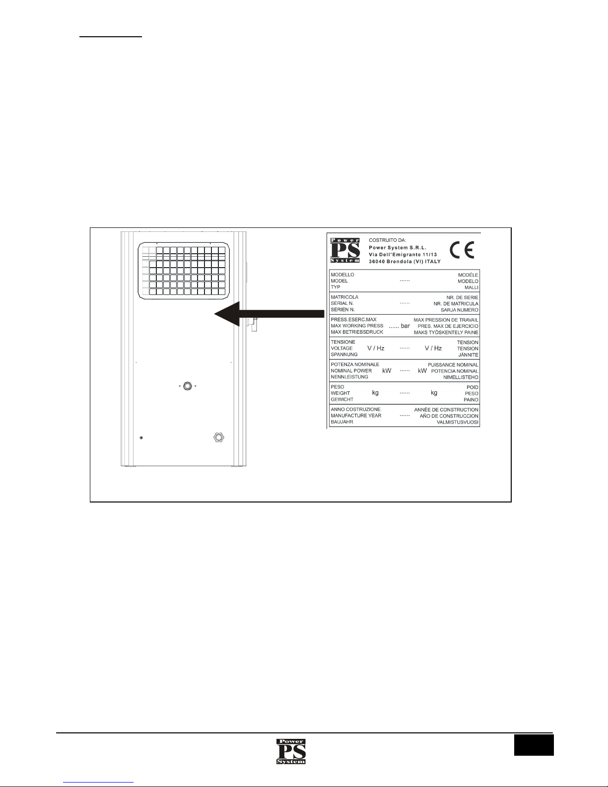
2.1 CE MARKING
The CE marking (FIG. 1) certifies the conformity of the compressor with the essential safety and health requirements contemplated by
the European Directives listed in the EC declaration of conformity.
It is an adhesive label made of silver coloured polyester with printing in black, with the following dimensions: L = 95 mm - H= 120
mm. It is applied on the outside, on the rear of the compressor. The following data are indicated legibly and indelibly on the plate:
• The logo, name and address of the manufacturer
• The CE mark
• The model
• The serial number
• The max. working pressure (bar)
• The voltage and frequency of the electric power supply (V / Hz)
• The nominal power (kW)
• The weight (kg)
• The year of manufacture
Left side
Fig.1 (CE marking)
Istruzioni per l’uso e manutenzione
Cod. OQ7.5ARG114 – GB
Emiss. 19-01-11 Rev. 0 - Agg. /
10
POWER SYSTEM SRL
Via dell’Emigrante, 11/13 - 36040 Brendola (VI) Italia
3 IMPORTANCE OF THE MANUAL
BEFORE USING THE COMPRESSOR THE AUTHORISED OPERATORS MUST READ AND
UNDERSTAND ALL PARTS OF THIS MANUAL.
This technical manual of “Instructions for use and maintenance” has been drawn up according to the indications given by the European
Directives, in order to ensure easy and correct understanding of the topics dealt with by the operators authorised to perform the use
and maintenance of the compressor concerned. If, despite the care taken by the manufacturer when drawing up the manual, these
operators find any problem in understanding it, in order to avoid incorrect personal interpretations that might endanger safety, they are
requested to apply promptly to the manufacturer for the correct explanations and any further information.
Before using the compressor, the authorised operators must read and understand all parts of this technical manual of “Instructions for
use and maintenance” and strictly follow all the rules in it, in order to ensure their own safety and that of other people, obtain the best
compressor performance, and ensure the maximum efficiency and long life of all its components. This manual must be at the disposal
of the authorised operators at all times and must always be kept safely, near the compressor.
THIS MANUAL MUST ALWAYS BE AT THE DISPOSAL OF THE AUTHORISED OPERATORS AND
MUST BE KEPT SAFELY, NEAR THE COMPRESSOR.
THE MANUFACTURER DECLINES ALL RESPONSIBILITY FOR ANY DAMAGE TO PERSONS,
ANIMALS AND THINGS RESULTING FROM FAILURE TO OBSERVE THE RULES AND WARNINGS
DESCRIBED IN THIS MANUAL.
THIS MANUAL MUST BE HANDED OVER TOGETHER WITH THE COMPRESSOR IF IT IS
TRANSFERRED TO ANOTHER USER.
THIS MANUAL REFLECTS THE STATE OF THE ART AT THE TIME THE COMPRESSOR WAS SOLD
AND CANNOT BE CONSIDERED INADEQUATE ONLY BECAUSE IT MAY BE UPDATED LATER IN
THE LIGHT OF NEW EXPERIENCE.
IF THE MANUAL IS LOST OR SPOILT, ASK THE MANUFACTURER FOR A NEW COPY, SPECIFYING
THE COMPRESSOR IDENTIFICATION DATA (SEE CE MARKING) AND THE REVISION.
3.1 NOTES FOR CONSULTATION
THE GENERAL DANGER SIGNAL AND THE FRAMED TEXT IN CAPITAL LETTERS DRAW THE
OPERATOR’S ATTENTION TO THE WARNINGS GIVEN IN THIS MANUAL.
N.B. (Nota Bene): framed text in capital letters.
Bold print: Highlights some significant sentences in the text.
Italics: Describes the captions of the figures and tables.
Istruzioni per l’uso e manutenzione
Cod. OQ7.5ARG114 – GB
Emiss. 19-01-11 Rev. 0 - Agg. /
11
POWER SYSTEM SRL
Via dell’Emigrante, 11/13 - 36040 Brendola (VI) Itali
a
3.2 INTENDED RECEIVERS (AUTHORISED OPERATORS)
This technical manual is intended exclusively for the operators authorised to carry out use and maintenance of the compressor,
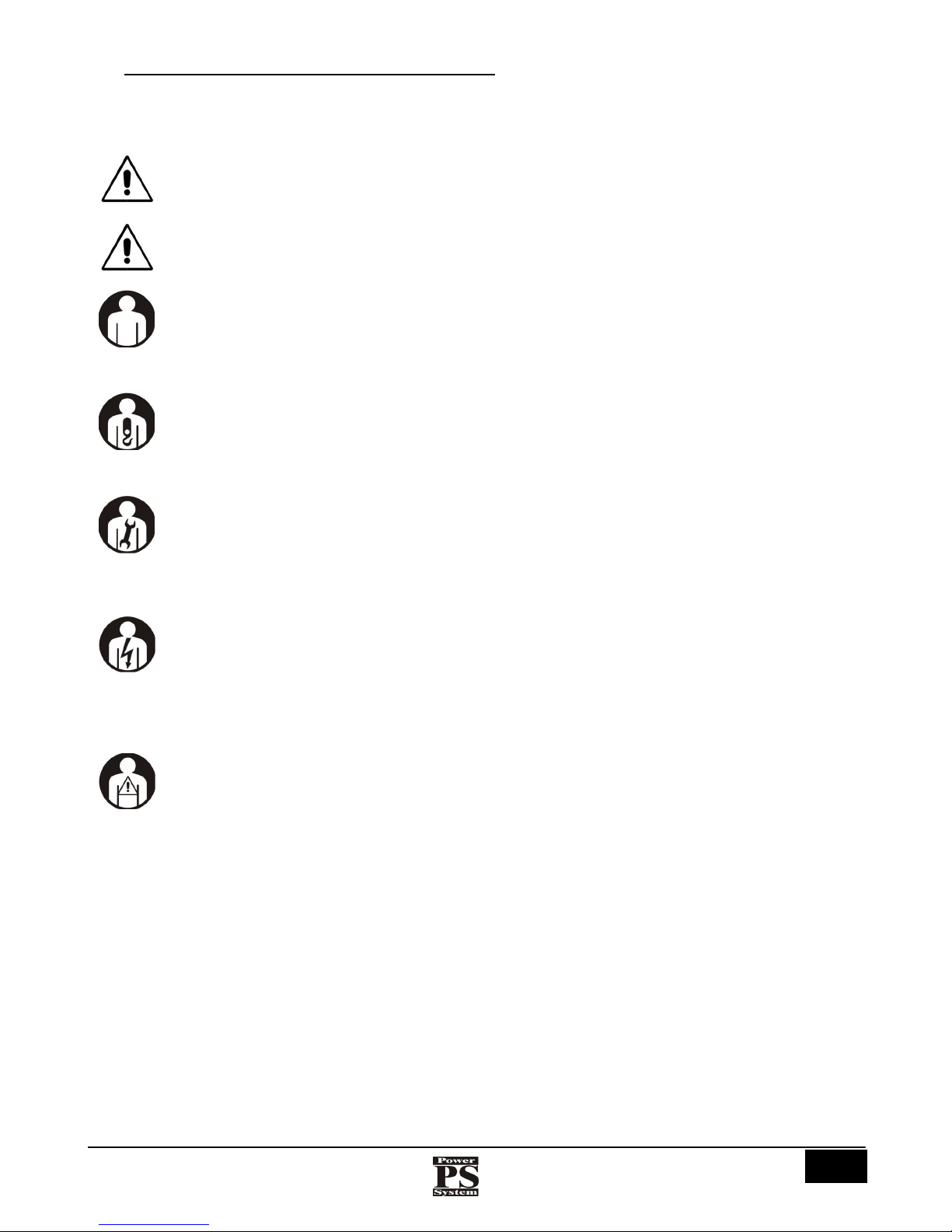
according to the specific technical and professional skills required for the type of activity. The symbols shown below placed at the
beginning of a chapter and/or of a paragraph indicate which operator is involved in the subject dealt with.
THE AUTHORISED OPERATORS MUST PERFORM ON THE COMPRESSOR ONLY THE ACTIVITIES
FOR WHICH THEY ARE SPECIFICALLY COMPETENT.
BEFORE CARRYING OUT ANY ACTIVITY ON THE COMPRESSOR, THE AUTHORISED OPERATORS
MUST ENSURE THAT THEY ARE IN FULL POSSESSION OF THEIR PHYSICAL AND MENTAL
FACULTIES IN ORDER TO ENSURE THAT THE SAFETY CONDITIONS ARE ALWAYS RESPECTED.
GENERAL OPERATOR
This is a professionally trained operator, over 18 years of age, in compliance with the laws in force in the country of use,
authorised only to switch on, use, fine-tune (obligatorily with the guards enabled and the machine switched off) and
switch off the compressor, absolutely respecting the instructions given in this manual, provided with the personal
protective equipment (PPE) contemplated in table 7 and occupying the positions described in fig. 9.
HANDLING OPERATOR
This is a professionally trained operator, over 18 years of age, in compliance with the laws in force in the country of use,
authorised to use fork-lift trucks, bridge cranes or cranes, to transport and handle the compressor and/or its parts safely,
provided with the personal protective equipment (PPE) contemplated in table 7 and occupying the positions described in
fig. 9.
MECHANICAL / HYDRAULIC / PNEUMATIC OPERATOR
This is a qualified technician, approved to perform only operations on the mechanical / hydraulic / pneumatic parts to
carry out adjustments, maintenance and/or repairs even with the guards disabled (with the consent of the safety
manager), absolutely respecting the instructions given in this manual or any other specific document supplied
exclusively by the manufacturer, provided with the personal protective equipment (PPE) contemplated in table 7 and
occupying the positions described in fig. 9.
ELECTRICAL OPERATOR
This is a qualified technician (electrician in possession of the technical and professional skills required by the
regulations in force), approved to perform only operations on electric devices to carry out adjustments, maintenance
and/or repairs even with the system live and with the guards disabled (with the consent of the safety manager),
absolutely respecting the instructions given in this manual or any other specific document supplied exclusively by the
manufacturer, provided with the personal protective equipment (PPE) contemplated in table 7 and occupying the
positions described in fig. 9.
COMPANY SAFETY MANAGER
This is a qualified technician designated by the Customer, in possession of the technical and professional skills required
by the regulations in force concerning the safety and health of workers in the place of work.
Istruzioni per l’uso e manutenzione
Cod. OQ7.5ARG114 – GB
Emiss. 19-01-11 Rev. 0 - Agg. /
12
POWER SYSTEM SRL
Via dell’Emigrante, 11/13 - 36040 Brendola (VI) Italia
MANUFACTURER’S TECHNICIAN
This is a qualified technician made available by the Manufacturer and/or by the authorised Dealer to carry out the
requested technical assistance, routine and special maintenance jobs and/or operations not listed in this manual which
require a specific knowledge of the compressor, provided with the personal protective equipment (PPE) contemplated in
table 7 and occupying the positions described in fig. 9.
In the manual you can also find, next to a table, a figure, or a text, a double line “║“; this indicates the parts of the manual that have
been varied with respect to the previous revision.
3.3 MACHINE OFF STATUS
It is obligatory to disconnect the supply of electric power before carrying out any kind of maintenance work and/or
adjustment on the compressor.
1) Main electric switch turned “OFF” and padlocked;
2) Electric power supply switch (Customer) turned “OFF”;
3) Pressurised air discharged from the compressor (see pressure gauge on compressor).
4) Reservoir air outlet valve closed.
3.4 ABBREVIATIONS
TAB. 1 lists some abbreviations used in the text of the “instructions for use and maintenance”.
appro
x.
Approximately
min
Minutes
chap.
Chapter
No.
Number
PPE
Personal Protective Equipment
page
Page
Right
Right
par.
Paragraph
h
Hours
Pos.
Position
EN
European Norm
REF.
Reference
e.g.
Example
s
Seconds
FIG.
Figure(s)
Left
Left
max.
Maximum
TAB.
Table
min.
Minimum
see
See
3.5 RESERVED RIGHTS
All information (text, drawings, diagrams, etc.) given here is reserved. No part of this manual may be reproduced and made known
(completely or in part) with any means of reproduction (photocopies, microfilm or other) without the Manufacturer’s authorisation in
writing.
All the trade marks mentioned belong to their respective owners.
Istruzioni per l’uso e manutenzione
Cod. OQ7.5ARG114 – GB
Emiss. 19-01-11 Rev. 0 - Agg. /
13
POWER SYSTEM SRL
Via dell’Emigrante, 11/13 - 36040 Brendola (VI) Itali
a
4 NAMING OF THE COMPRESSOR
The name of the compressor is:
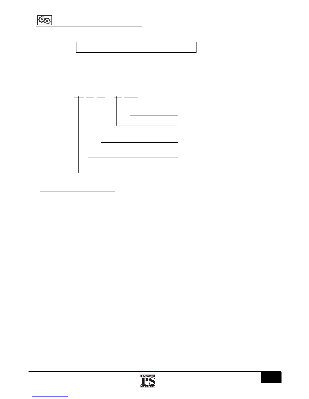
4.1 NAMING OF THE MODELS
The models are named according to the motor power.
Name example:
PS 20 30 – 10 PM
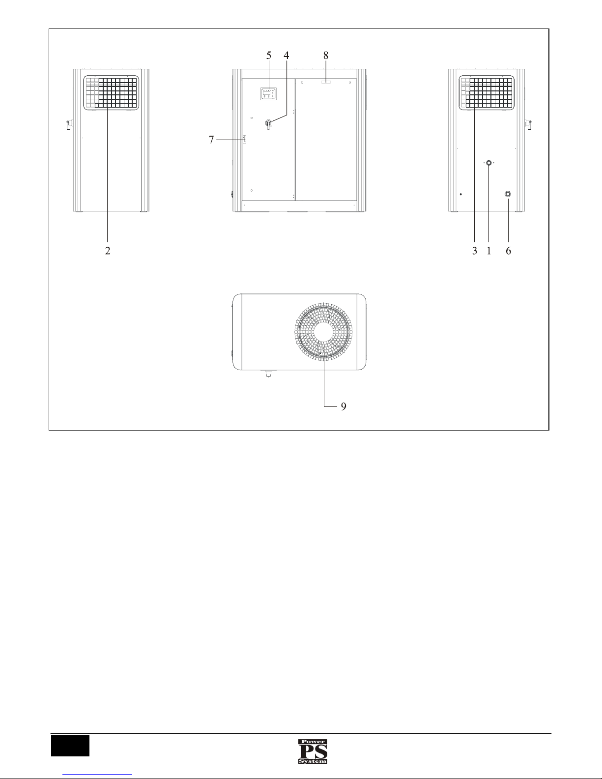
4.2 NAMING OF THE COMPONENTS
FIG. 2 and 3 show and name the main components of the compressors listed above.
ROTARY SCREW COMPRESSOR
Pressure (7,5 – 10 – 13 )
Power S
y
stem
Power (kW)
Compressor series
Series PM (Permanent Magnet)
Istruzioni per l’uso e manutenzione
Cod. OQ7.5ARG114 – GB
Emiss. 19-01-11 Rev. 0 - Agg. /
14
POWER SYSTEM SRL
Via dell’Emigrante, 11/13 - 36040 Brendola (VI) Italia
Fig.2
Left side
Right side
Fron
t
Overhead view
Istruzioni per l’uso e manutenzione
Cod. OQ7.5ARG114 – GB
Emiss. 19-01-11 Rev. 0 - Agg. /
15
POWER SYSTEM SRL
Via dell’Emigrante, 11/13 - 36040 Brendola (VI) Itali
a
Key:
1) Air output
2) Left side intake prefilter
3) Right side intake prefilter
4) Isolating switch
5) Control board
6) Cable entry
7) Front panel handle
8) Front panel handle
9) Electric fans
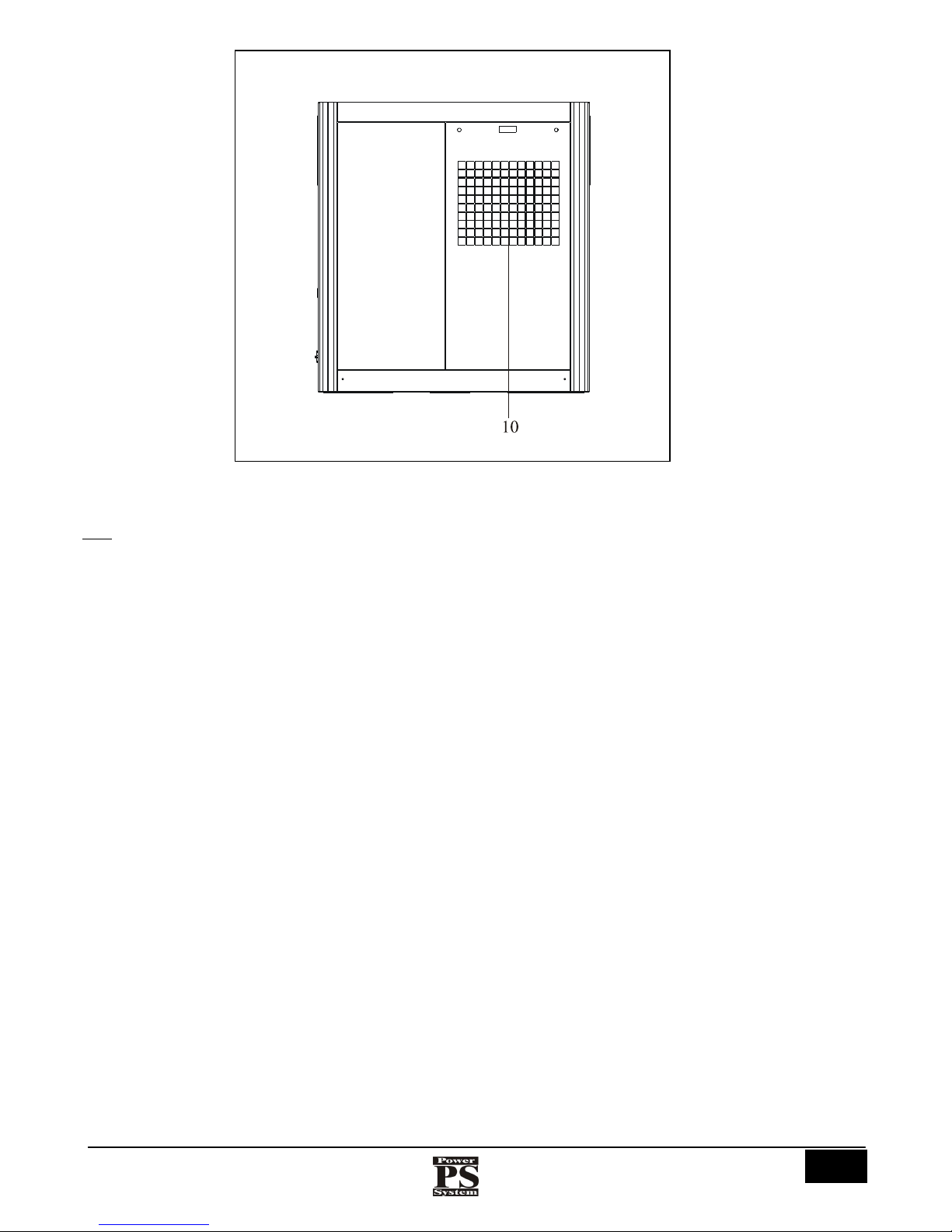
10) Dryer cooling air expulsion (if present)
Fig.3
Rear
Istruzioni per l’uso e manutenzione
Cod. OQ7.5ARG114 – GB
Emiss. 19-01-11 Rev. 0 - Agg. /
16
POWER SYSTEM SRL
Via dell’Emigrante, 11/13 - 36040 Brendola (VI) Italia
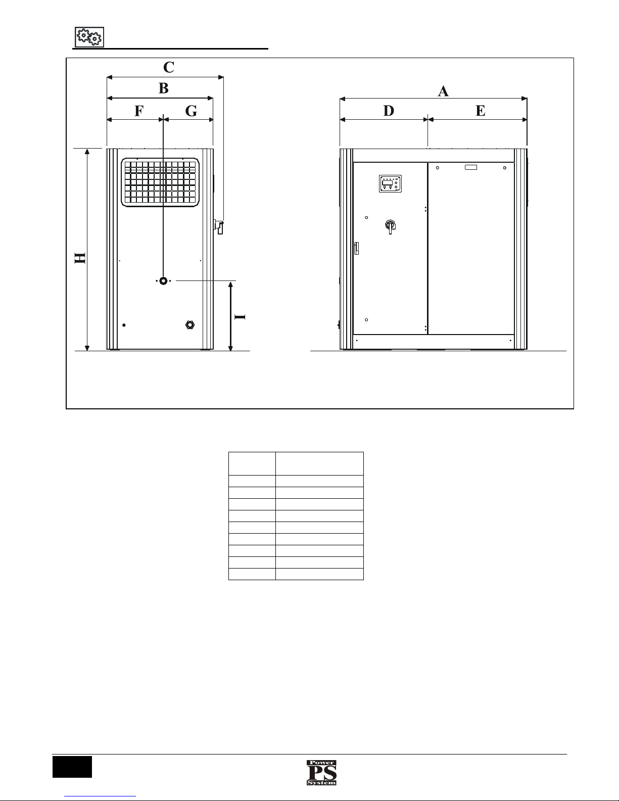
5 OVERALL DIMENSIONS (mm)
МОD. PS 2000
A 1400
B 800
C 875
D 660
E 745
F 425
G 375
H 1500
I 515
Fig.4
Front
Left side
Istruzioni per l’uso e manutenzione
Cod. OQ7.5ARG114 – GB
Emiss. 19-01-11 Rev. 0 - Agg. /
17
POWER SYSTEM SRL
Via dell’Emigrante, 11/13 - 36040 Brendola (VI) Itali
a
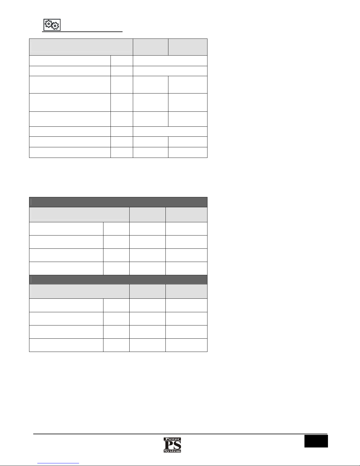
6 TECHNICAL DATA
* : without packaging
TAB.2
МОДЕЛЬ
PS2030DV PS2037DV
Max. delivery temperature
°C
110
Intake air temperature
°C
MIN
. 0° - MAX. 40°
Motor power / service factor
kW/Hp
30 (41)
FS1.15
37 (51)
FS1.15
Fan motor power
400V/50 Hz
W
790 790
Fan motor speed
400V/50 Hz
rpm
1310 1310
Noise
dB (A)
69
Compressor weight *
kg
550 570
Compressor weight with dryer *
kg
600 620
8 bar
Mod.
PS2030PM PS2037PM
Type of drive
400V/50 Hz
Direct
Direct
Delivery pressure
bar
min. 4 -
max. 11
min. 4 - max.
11
Full load current
400V/50 Hz
A
55 66
Compressor motor speed
400V/50 Hz
giri/min
Variable
800 ÷ 5500
Variable
800 ÷ 3700
10 bar
Mod.
PS2030PM PS2037PM
Type of drive
400V/50 Hz
Direct Direct
Delivery pressure
bar
min. 4 max. 11
min. 4 - max.
11
Full load current
400V/50 Hz
A
55 66
Compressor motor speed
400V/50 Hz
giri/min
Variable
800 ÷ 4900
Variable
900 ÷ 5500
 Loading...