

Power Studio PWM10000Q User Instructions
AMPLIFIER
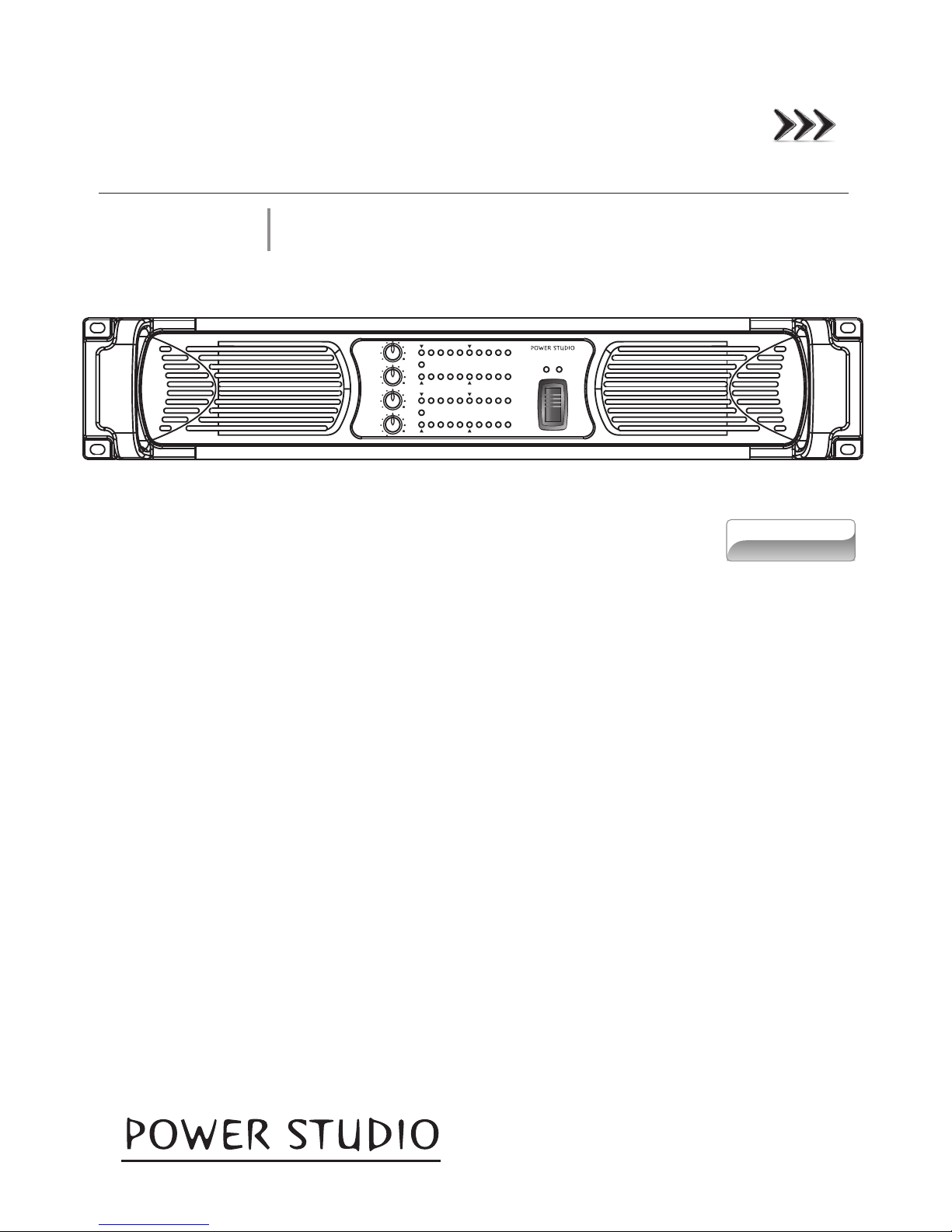
PWM10000Q
User Instructions
This booklet contains important information concerning the proper and safe operation of your new amplifier..
Made in Taiwan
Index
01 Precautions
02 Introduction
03 Front Panel
04 Rear Panel
05 Operation and Performance
POWERPAL
CH A
CH B
CH C
CH D
HI-IMP
CLIP
SIG
-20dB-15dB -10dB
-4dB
VPL
CPL
VHF TEMP
MUTE
SIG
-20dB-15dB -10dB
-4dB
VPL
CPL
VHF TEMP
MUTE
HI-IMP
CLIP
HI-IMP
CLIP
SIG
-20dB-15dB -10dB
-4dB
VPL
CPL
VHF TEMP
MUTE
SIG
-20dB-15dB -10dB
-4dB
VPL
CPL
VHF TEMP
MUTE
HI-IMP
CLIP
PWM -10 000 Q
BRIDGE A+B
BRIDGE C+D
PROFESSIONAL POWER AMPLIFIER
Precautions Introduction Front Panel Rear Panel Operation and Performance
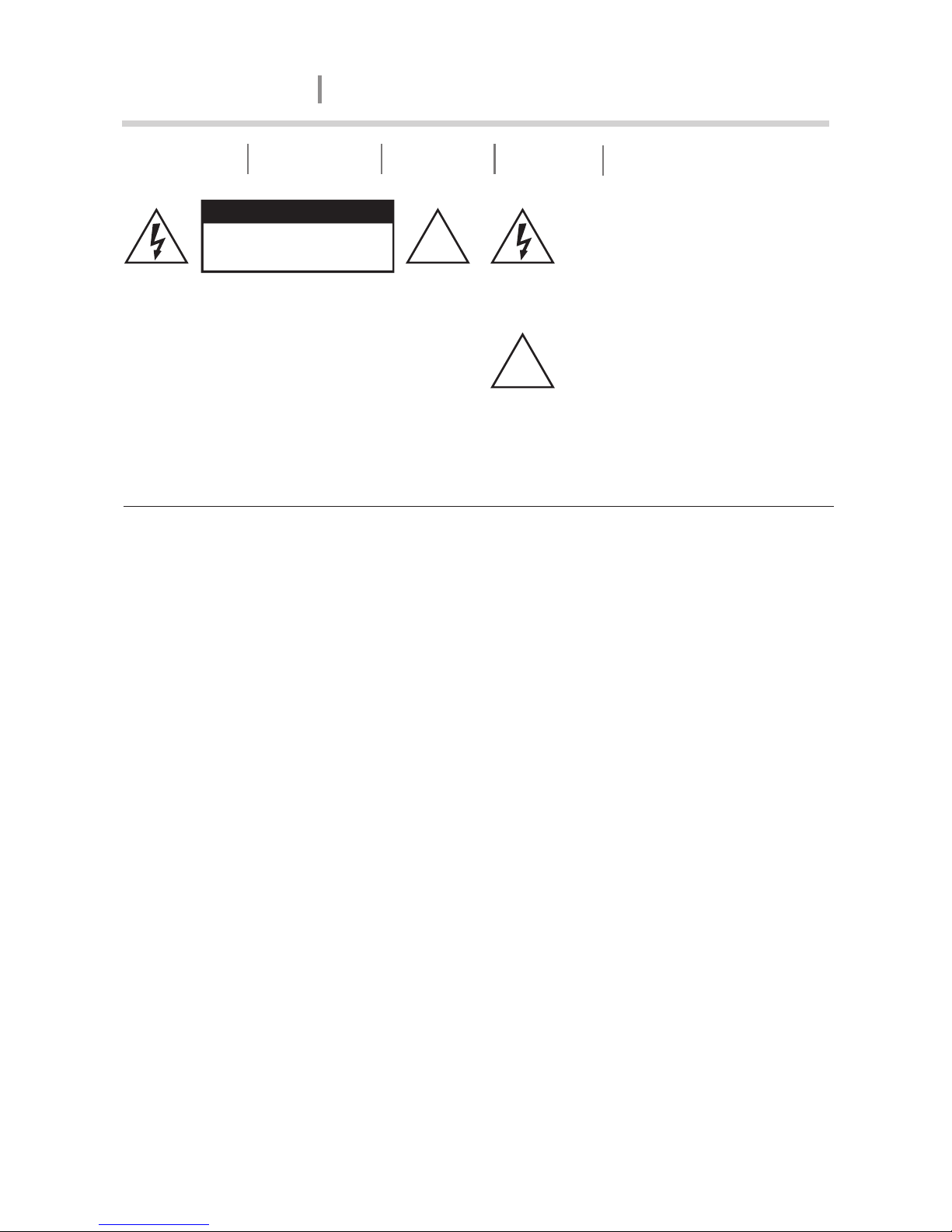
CAUTION
RISK OF ELECTRIC SHOCK
DO NOT OPEN
CAUTION: To reduce the risk of electrical
shock, do not remove the cover
(or back). No user serviceable
parts inside; refer servicing to
qualified personnel.
WARNING: To reduce the risk of fire or
electrical shock, do not expose
this appliance to rain or
moisture.
This symbol, wherever it appears,
alerts you to the presence of
uninsulated dangerous voltage
inside the enclosure - voltage that
may be sufficient to constitute a
risk of shock.
This symbol, wherever it appears,
alerts you to important operating
and maintenance instructions in
the accompanying literature. Read
the manual.
!
!
Important Precautions
To reduce the risk of electrical shock or fire, do not expose this unit in rain or
moisture.
Make sure that the AC Mains voltage is correct and matches the voltage printed on
the rear panel of the amplifier (110 V or 220V)
Do not spill water or other liquids into or on to your unit.
Do not attempt to operate this unit if the power cord has been frayed or broken.
Do not attempt to remove or break off the ground prong from the electrical cord.
This prong is used to reduce the risk of electrical shock and fire in case of an
internal short.
Disconnect mains power before making any type of connection.
Do not remove the cover under any conditions. There are no user serviceable
parts inside.
Never plug this unit in to a dimmer pack.
Always be sure to mount this unit in an area that will allow proper ventilation. Allow
about 6” (15cm) between this device and wall.
Do not attempt to operate this unit if it becomes damaged.
This unit is intended for indoor use only, use of this product outdoors voids all
warranties.
During long periods of non-use, disconnect the unit’s mains power.
1
AMPLIFIER
PWM10000Q

Always mount this unit in a safe and stable manner.
Power cords should be routed so they are not likely to be walked on, pinched by items
placed upon or against them.
Cleaning -The outside of the unit should be wipe down with a soft cloth and mild
cleaner when needed.
Heat -The amplifier should be situated away from heat sources such as radiators,
heat registers, stoves, or other appliances (including amplifiers) that produce heat.
The fixture should be serviced by qualified service personnel when:
A. The power-supply cord or the plug has been damaged.
B. Objects have fallen, or liquid has been spilled into the unit.
C. The appliance has been exposed to rain or water.
D. The fixture does not appear to operate normally or exhibits a marked change in
performance.
Precautions Introduction Front Panel Rear Panel Operation and Performance
AMPLIFIER
PWM10000Q
Introduction
Congratulations and thank you for purchasing PWM-10000Q amplifier. This amplifier
is a representation of PowerStudio’s continuing commitment to produce the best and
highest quality audio products at an affordable price. This amplifier is designed to
provide a big impact in sound reproduction. Please read and understand this manual
completely before attempting to operate your new amplifier. This booklet contains
important information concerning the proper and safe operation of your new amplifier.
Unpacking: Every PWM-10000Q amplifier has been thoroughly tested and
has been shipped in perfect operating condition. Carefully check the shipping carton
for damage that may have occurred during shipping. If the carton appears to be
damaged, carefully inspect your unit for any damage and be sure all accessories
necessary to operate the system have arrived intact. In the event damage has been
found or parts are missing, please contact your dealer for further instructions.
Installation: This amplifier is designed to mount into a standard 19”rack. The
front panel provides four holes used to screw the unit into a rack. The unit also
provides a way to rear mount the unit into a rack for added security. Rear mounting the
unit is especially recommended if the unit is to mount into a mobile rack.
2
3
Precautions Introduction Rear Panel Operation and PerformanceFront Panel
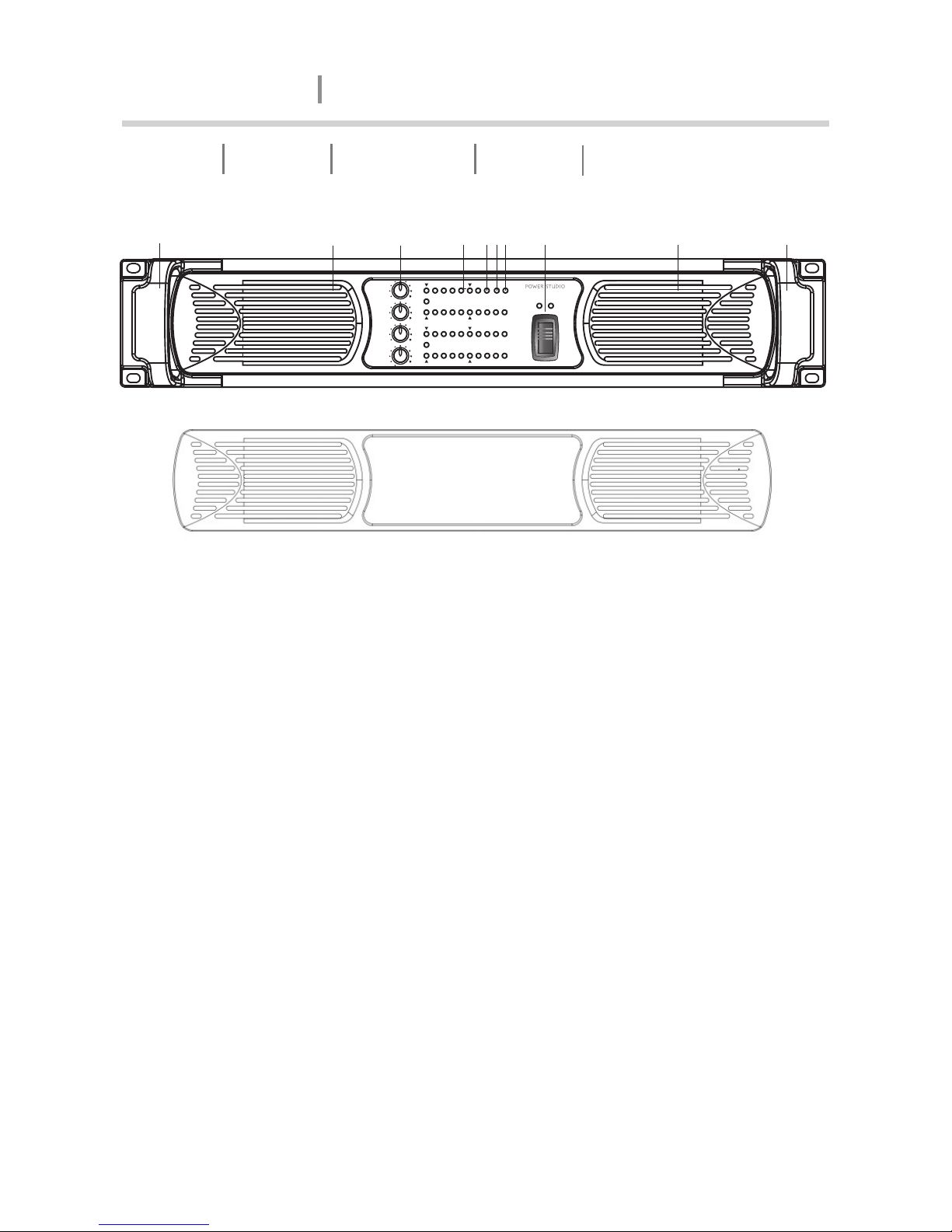
Front Panel
AMPLIFIER
PWM10000Q
Figure 1
1. Carry/protection handle - Both handles can be used to carry the amplifier, they also act
as protection for the front panel.
2. Front panel fan grill & filters - Detachable snap-in front panel design for the ease of
dust filters replacement (as Figure 1A), foam filters are located behind the front panel to
prevent dust entering the amplifier.
3. Input level attenuators - These controls are used to alter the signal level entering the
amplifier. They are calibrated to help set up active loudspeaker systems or cut down
unwanted noise from the input signal.
4. Clip/limit indicator - This indicator tells when the amplifier output is clipping or limiting.
The two different states can be told apart:
When the clip limiter is engaged it flickers briefly.
When the clip limiter is not engaged it lights for a longer period.
5. VHF protect indicator - This indicator lights when constant signals, above 12KHz at full
power, are present at the output terminals. When this happens the input signal is muted
and the process cycles until the VHF signal is no longer present.
6. Over temperature protect indicator - This indicator lights if the amplifier tries to operate
above its maximum operating temperature (90°C). The indicator first comes on as a
warning to either turn down the input level or check the cooling arrangements after which
point the amplifier will mute the input signal. When the cooling fans have returned the
output heatsinks to the normal operating temperature the input signal is unmuted.
7. Mute indicator - This indicator will light when if a fault condition on the channel. The
possible conditions may be due to overload, overheat, CPL and VHF protection.
8. AC Power switch - This is used to activate the amplifier.
5
4
2
2
POWERPAL
CH A
CH B
CH C
CH D
HI-IMP
CLIP
SIG
-20dB-15dB -10dB
-4dB
VPL
CPL
VHF TEMP
MUTE
SIG
-20dB-15dB -10dB
-4dB
VPL
CPL
VHF TEMP
MUTE
HI-IMP
CLIP
HI-IMP
CLIP
SIG
-20dB-15dB -10dB
-4dB
VPL
CPL
VHF TEMP
MUTE
SIG
-20dB-15dB -10dB
-4dB
VPL
CPL
VHF TEMP
MUTE
HI-IMP
CLIP
PWM -10 000Q
BRIDGE A+B
BRIDGE C+D
6
1
3
8 17
Figure 1 A

21 3 4
Figure 2
1. AC line cord - Mains input 110V or 220V
operation (Not selectable)
2. The DIP - switch features - The following
features may be adjusted using the DIPswitches on the rear panel of the amplifier.
Gain - Globally set for all channels, from
+23dB to +44dB in 3dB steps.
Option active - Not currently implemented.
Fan Masked - When on, engages the
intelligent fan feature; fan speed is lowered
when no signal is present.
Bridge A+B / Bridge C+D - Switches the channel pairs into bridge mode operation, an
automatic -6dB gain compensation is applied.
VPL - The Voltage Peak Limiter provides optimum peak voltage settings for each channel.
Level selections vary by model within the PWM-10000Q amplifier.
Mode - Select VPL mode to either Hard or Soft operation. For channels driving sub-woofers
and low-frequency drivers, it is recommended to use the Hard setting for optimal operation.
For mid-and-high-frequency drivers, always select Soft.
3. Input connectors - This amplifier is equipped with XLR-F input connector.
4. Output connectors - PWM-10000Q offered with Neutrik NL4FC Speakon output connectors.
4
~110V 60 Hz
~220V 5 0Hz
MADE IN TAI WAN
CH D CH C+D CH B CH A+B
1+ CH A+
1 - CH A -
2+ CH B+
2 - CH B -
XLR PIN1 : Gnd / PIN2 : + / PIN 3 : -
CH ACH BCH CCH D
44dB
41dB
38dB
35dB
32dB
29dB
26dB
23dB
VPL - VOLTAGE PEAK LIMI TER
141V
118V
100V
85V
71V
59V
50V
42V
CH CCH D
VPLVPL
MODE
MODE
VPL-MODE
SWITCH
SOFT
HARD
GAIN
ON
CH ACH B
VPLVPL
MODE
MODE
OPTION ACTIVE
FAN MASKED
BRIDGE C+D
BRIDGE A+B
SPEAKER OUTPUTS
1+ CH B+
1 - CH B -
WIRING NORMAL:CLASS 2 BRIDGED:CLASS 3
1+ CH C+
1 - CH C -
2+ CH D+
2 - CH D -
1+ CH D+
1 - CH D -
BALANCED INPUTS
1+ : +
2 - : -
BRIDGE
1+ : +
2 - : -
BRIDGE
PUSH
Precautions Introduction Front Panel Operation and PerformanceRear Panel
Rear Panel
44dB
41dB
38dB
35dB
32dB
29dB
26dB
23dB
VPL - VOLTA G E P E AK LIM I TER
141V
118V
100V
85V
71V
59V
50V
42V
CH CCH D
VPLVPL
MODE
MODE
VPL-MODE
SWITCH
SOFT
HARD
GAIN
ON
CH ACH B
VPLVPL
MODE
MODE
OPTION ACTIVE
FAN MASKED
BRIDGE C+D
BRIDGE A+B
Audio inputs-four-channel models
XLR PIN1 : Gnd / PIN2 : + / PIN 3 : -
CH ACH BCH CCH D
BALANCED INPUTS
PUSH
Speakon output-four-channel models
CH D CH C+ D CH B CH A+B
1+ CH A+
1 - CH A -
2+ CH B+
2 - CH B -
SPEAKER OUTPUTS
1+ CH B+
1 - CH B -
WIRING NORMAL:CLASS 2 BRIDGED:CLASS 3
1+ CH C+
1 - CH C -
2+ CH D+
2 - CH D -
1+ CH D+
1 - CH D -
1+ : +
2 - : -
BRIDGE
1+ : +
2 - : -
BRIDGE
PUSH PUSH
PUSHPUSH
ON
1 2 3 4 5 6 7ON1 2 3 4 5 6 7 8ON1 2 3 4 5 6 7 8
ON
1 2 3 4 5 6 7ON1 2 3 4 5 6 7 8ON1 2 3 4 5 6 7 8
AMPLIFIER
PWM10000Q
PUSH
PUSH
5
Precautions Introduction Front Panel Rear Panel Operation and Performance
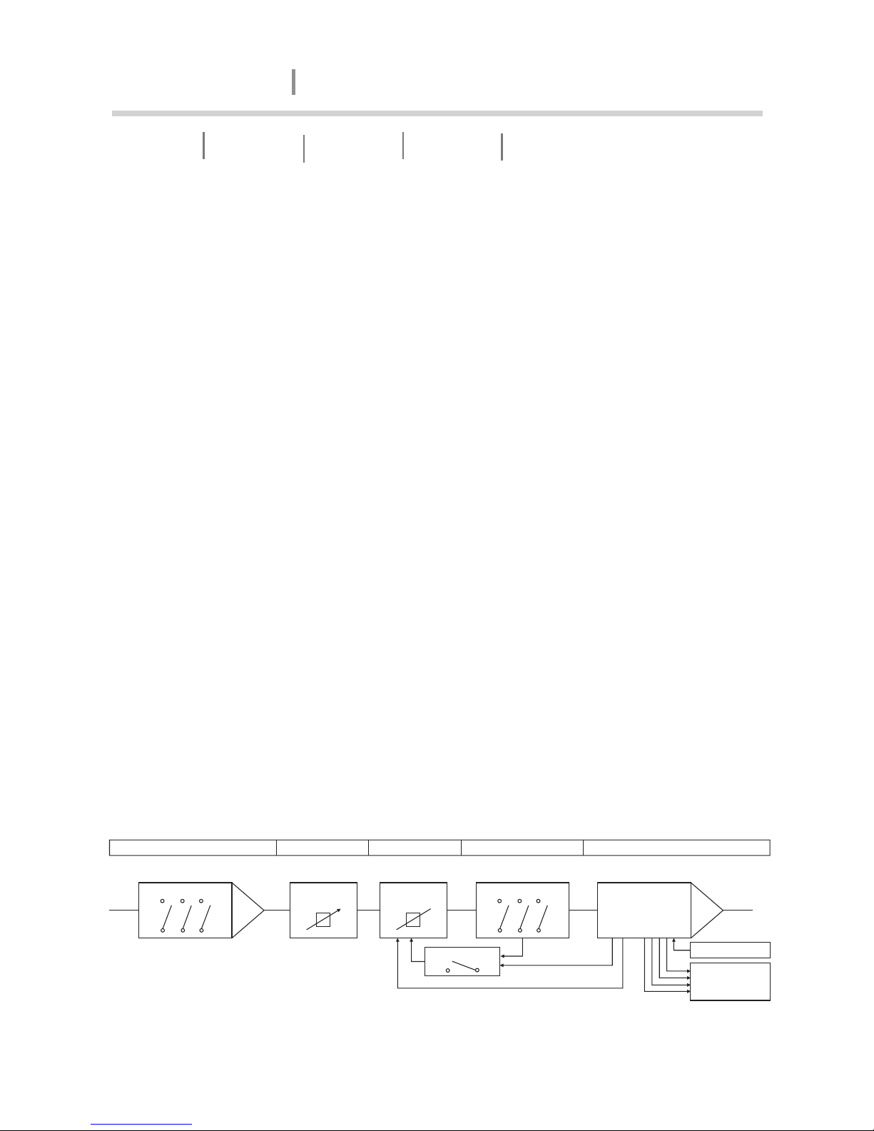
Operation and Performance
Signal flow blocks
The PWM Series amplifier has the same signal flow, and the same feature sets. The
only internal differences are in the maximum output current per channel and VPL
settings.
The input stage of PWM Series amplifier has a high sensitivity to provide ample
system headroom. This in effect means that the input stage is almost impossible to
clip.
Overall amplifier input gain is adjusted using the input stage DIP-switches. Please
note that the gain setting is global, affecting all channels. Following the input stage,
the dedicated level control on each channel allows signal attenuation from 0 dB to
minus.
The Current Peak Limiter (CPL) section dynamically limits the input signal based on
three parameters: sensed current level, feedback from the output stage, and sensed
voltage clip from the VPL (and output amplifier voltage clip if “Soft Clip” is activated).
This ensures that power output is maintained within the design limits of the amplifier.
The adjustable Voltage Peak Limiter (VPL) sets the maximum output voltage and
therefore also the maximum output power. Eight different voltage stages are
available using the DIP-switches on the rear panel.
The sophisticated output section monitors faults and generates appropriate
warnings, which are displayed on the amplifier front panel. These alerts allow the
operator to adjust system settings and thereby avoid problems. In the rare event that
condition are extraordinarily severe, the amplifier will shut down until the fault or
problem setting ha been rectified or adjusted. These sensing circuits are also
employed to feed back voltage and current level information, via a side chain, to the
limiters. Sensing circuit also transmit local amplifier module temperature and power
supply temperature to the appropriate protection mechanisms. Read the Protection,
Faults and Warnings section for further details.
Figure 3
PWM-10000Q signal flow
Gain select switches Front panel
potentiometer
Dynamic Gain
reduction
VPL select switches
Class TD
Hard/Soft switch
Voltage Clip sensing
Current clip sensing
Control Mute
Monitoring Level
Temperature
Fault/Warning
Input Amplifier Level control Clip Limiter Voltage Peak Limiter Output Power Amplifier
AMPLIFIER
PWM10000Q
 Loading...