

Page 1
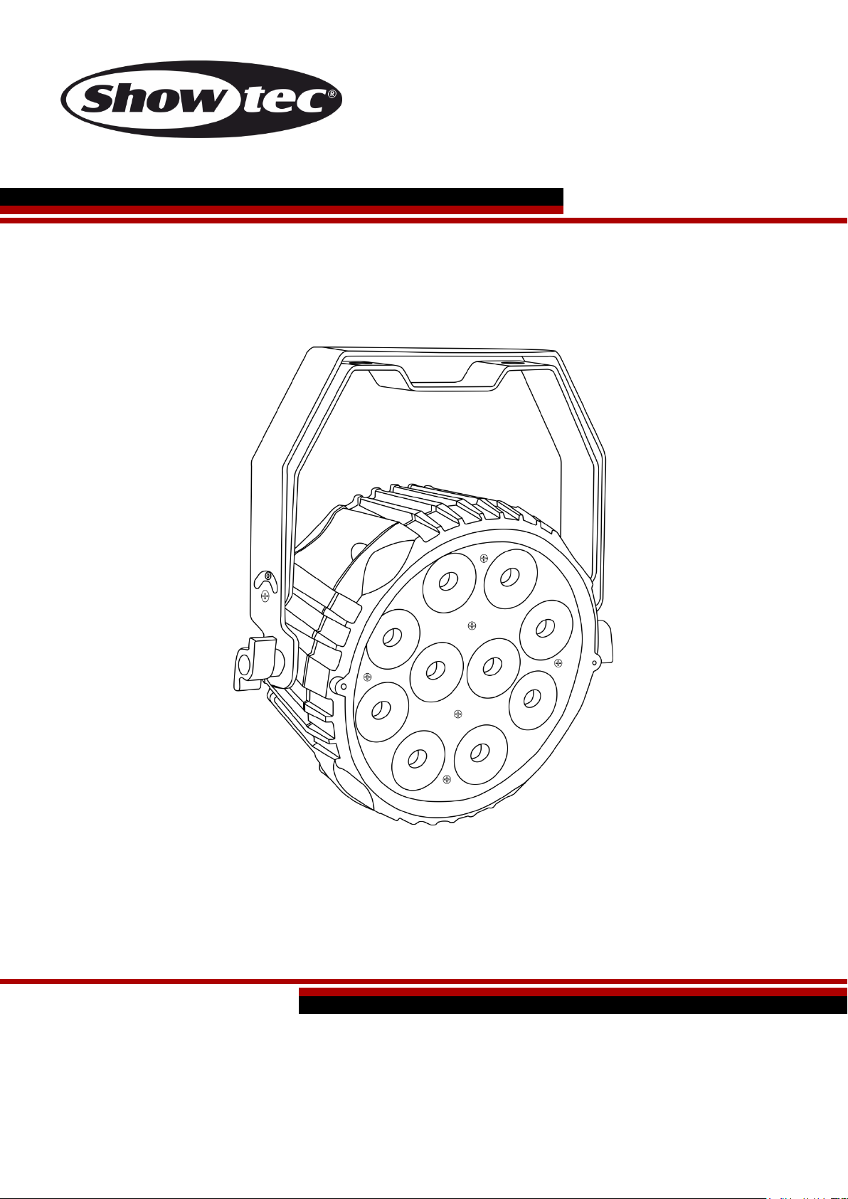
Powerspot 10 SW White V1
Highlite International B.V. – Vestastraat 2 – 6468 EX – Kerkrade – the Netherlands
Ordercode: 42578
MANUAL
ENGLISH
Page 2

Ordercode: 42578
Powerspot 10 SW White
Table of contents
Warning ............................................................................................................................................................................... 2
Safety Instructions ......................................................................................................................................................... 2
Operating Determinations .......................................................................................................................................... 4
Rigging ............................................................................................................................................................................ 4
Connection with the mains......................................................................................................................................... 5
Return Procedure .......................................................................................................................................................... 6
Claims .............................................................................................................................................................................. 6
Description of the device ................................................................................................................................................. 7
Frontside.......................................................................................................................................................................... 7
Backside ......................................................................................................................................................................... 8
Installation ........................................................................................................................................................................... 8
Set Up and Operation ....................................................................................................................................................... 8
Control Modes ............................................................................................................................................................... 9
One Powerspot 10 SW (Auto Run Mode, Built-in programs and Static Color Mode) ................................... 9
One Powerspot 10 SW (Sound-controlled) ........................................................................................................... 9
Multiple Powerspots 10 SW (Master/Slave control) ............................................................................................. 9
Multiple Powerspots 10 SW (DMX Control) ..........................................................................................................10
Fixture Linking ...............................................................................................................................................................11
Data Cabling ...............................................................................................................................................................11
Control Panel ...............................................................................................................................................................12
Control Mode ..............................................................................................................................................................12
DMX Addressing ..........................................................................................................................................................12
Menu Overview ...........................................................................................................................................................13
Main Menu Options ....................................................................................................................................................14
Auto Run Mode ........................................................................................................................................................14
Built-in Programs .......................................................................................................................................................14
Static Color control ..................................................................................................................................................15
Sound control mode ...............................................................................................................................................15
DMX Addressing/ DMX configuration ..................................................................................................................15
Slave Mode ...............................................................................................................................................................15
Settings .......................................................................................................................................................................16
Info ..............................................................................................................................................................................16
DMX Channels .............................................................................................................................................................17
3 channels .................................................................................................................................................................17
6 channels .................................................................................................................................................................17
7 channels .................................................................................................................................................................17
Maintenance ....................................................................................................................................................................19
Troubleshooting ...............................................................................................................................................................19
No Light .........................................................................................................................................................................19
No Response to DMX..................................................................................................................................................19
Product Specifications ....................................................................................................................................................21
Dimensions ........................................................................................................................................................................22
1
Page 3
Ordercode: 42578
Powerspot 10 SW White
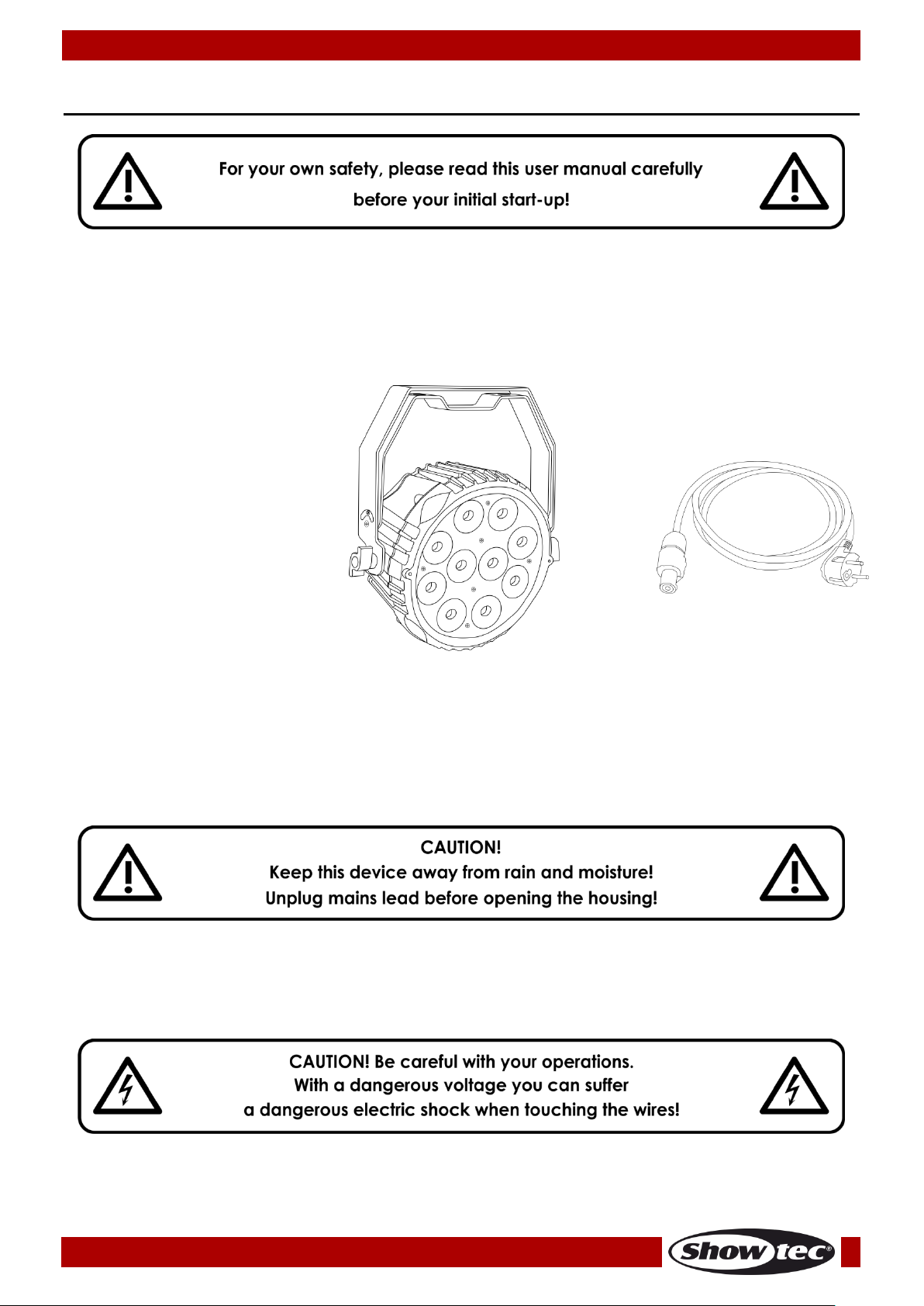
Your shipment includes:
Showtec Powerspot 10 SW
Pro Power cable (1,5 m)
User manual
be qualified
follow the instructions of this manual
Warning
Unpacking Instructions
Immediately upon receiving this product, carefully unpack the carton and check the contents to ensure
that all parts are present, and have been received in good condition. Notify the dealer immediately and
retain packing material for inspection if any parts appear damaged from shipping or the carton itself
shows signs of mishandling. Save the carton and all packing materials. In the event that a fixture must be
returned to the factory, it is important that the fixture be returned in the original factory box and packing.
LED Expected Lifespan
LEDs gradually decline in brightness over time. HEAT is the dominant factor that leads to the acceleration
of this decline. Packaged in clusters, LEDs exhibit higher operating temperatures than in ideal or singular
optimum conditions. For this reason, when all color LEDs are used at their fullest intensity, life of the LEDs is
significantly reduced. If improving the lifespan is of higher priority, place care in providing for lower
operational temperatures. This may include climatic-environmental and the reduction of overall
projection intensity.
Safety Instructions
Every person involved with the installation, operation and maintenance of this device has to:
2
Page 4

Ordercode: 42578
Powerspot 10 SW White
Before the initial start-up, please make sure that there is no damage caused by transportation.
Should there be any, consult your dealer and do not use the device.
To maintain perfect condition and to ensure a safe operation, it is absolutely necessary for the user to
follow the safety instructions and warning notes contained in this manual.
Please consider that damages caused by manual modifications to the device are not subject to
warranty.
This device contains no user-serviceable parts. Refer servicing to qualified technicians only.
IMPORTANT:
The manufacturer will not accept liability for any resulting damages caused by the non-observance of
this manual or any unauthorized modification to the device.
• Never let the power cord come into contact with other cables! Handle the power cord and all
connections with the mains with particular caution!
• Never remove warning or informative labels from the unit.
• Never use anything to cover the ground contact.
• Never lift the fixture holding it by the projector-head, as the mechanics may be damaged. Always
hold the fixture by the transport handles.
• Never place any material over the lens.
• Never look directly into the light source.
• Never leave any cables lying around.
• Never loosen the screws of the rotating gobo otherwise you risk opening of the ball bearing.
• Do not insert objects into air vents.
• Do not connect this device to a dimmerpack.
• Do not switch the device on and off in short intervals, as this will reduce the device’s life.
• Do not touch the device’s housing bare-handed during its operation (housing becomes very hot).
Allow the fixture to cool for at least 5 minutes before handling.
• Do not shake the device. Avoid brute force when installing or operating the device.
• Only use the device indoors, avoid contact with water or other liquids.
• Only operate the fixture after having checked if the housing is firmly closed and all screws are tightly
fastened.
• Only operate the device after having familiarized with its functions.
• Avoid flames and do not put close to flammable liquids or gases.
• Always keep the case closed while operating.
• Always allow a free air space of at least 50 cm around the unit for ventilation.
• Always disconnect power from the mains, when device is not used or before cleaning! Only handle
the power cord holding it by the plug. Never pull out the plug by tugging the power cord.
• Make sure that the device is not exposed to extreme heat, moisture or dust.
• Make sure that the available voltage is not higher than stated on the rear panel.
• Make sure that the power cord is never crimped or damaged. Check the device and the power
cord from time to time.
• If the lens is obviously damaged, it has to be replaced.
• If device was dropped or struck, disconnect mains power supply immediately. Have a qualified
engineer inspect for safety before operating.
• If the device has been exposed to drastic temperature fluctuation (e.g. after transportation), do not
switch it on immediately. The arising condensation water might damage your device. Leave the
device switched off until it has reached room temperature.
• If your Showtec device fails to work properly, discontinue the use immediately. Pack the unit securely
(preferably in the original packing material), and return it to your Showtec dealer for service.
• For adult use only. The fixture must be installed beyond the reach of children. Never leave the unit
running unattended.
• Never attempt to bypass the thermostatic switch or fuses.
• For replacement use fuses of same type and rating only.
3
Page 5
Ordercode: 42578
Powerspot 10 SW White
• The user is responsible for correct positioning and operating of the Powerspot 10 SW. The
manufacturer will not accept liability for damages caused by the misuse or incorrect installation of
this device.
• This device falls under protection class I. Therefore it is essential to connect the yellow/green
conductor to earth.
• Repairs, servicing and electric connection must be carried out by a qualified technician.
• WARRANTY: Till one year after date of purchase.
Operating Determinations
• This device is not designed for permanent operation. Consistent operation breaks will ensure that the
device will serve you for a long time without defects.
• The minimum distance between light output and the illuminated surface must be bigger than 1
meter.
• The maximum ambient temperature t
• The relative humidity must not exceed 50 % with an ambient temperature of 40° C.
• If this device is operated in any other way than the one described in this manual, the product may
suffer damages and the warranty becomes void.
• Any other operation may lead to dangers like short-circuit, burns, electric shock, crash, etc.
= 40°C must never be exceeded.
a
You endanger your own safety and the safety of others!
Rigging
Please follow the European and national guidelines concerning rigging, trussing and all
other safety issues.
Do not attempt the installation yourself !
Always let the installation be carried out by an authorized dealer !
Procedure:
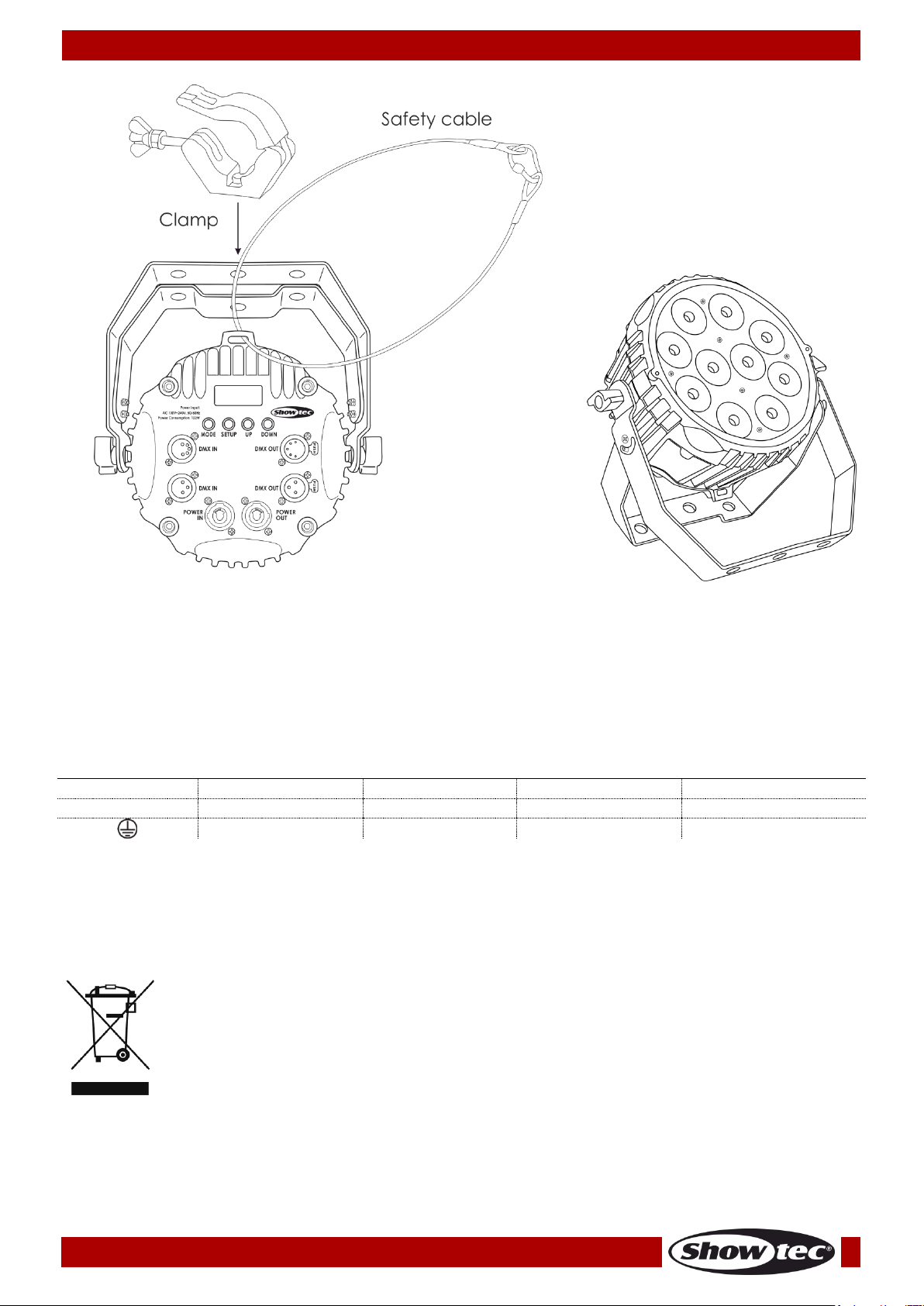
• If the Powerspot is lowered from the ceiling or high joists, professional trussing systems have to be
used.
• Use a clamp to mount the Powerspot, with the mounting bracket, to the trussing system.
• The Powerspot must never be fixed swinging freely in the room.
• The installation must always be secured with a safety attachment, e.g. an appropriate safety net or
safety cable.
• When rigging, derigging or servicing the Powerspot, always make sure, that the area below the
installation site is secured and that there are not any unauthorized people around.
4
Page 6
Ordercode: 42578
Powerspot 10 SW White
International
EU Cable
UK Cable
US Cable
Pin
L
BROWN
RED
YELLOW/COPPER
PHASE
N
BLUE
BLACK
SILVER
NEUTRAL
YELLOW/GREEN
GREEN
GREEN
PROTECTIVE GROUND
The Powerspot 10 SW can be placed on a flat stage floor or mounted to any kind of truss with a clamp.
Improper installation can cause serious injuries and/or damage of property!
Connection with the mains
Connect the device to the mains with the power-plug.
Always check if the right color cable is connected to the right place.
Make sure that the device is always properly connected to the earth!
Improper installation can cause serious injuries and/or damage of property!
5
Page 7
Ordercode: 42578
Powerspot 10 SW White
Return Procedure
Returned merchandise must be sent prepaid and in the original packing, call tags will not be issued.
Package must be clearly labeled with a Return Authorization Number (RMA number). Products returned
without an RMA number will be refused. Highlite will not accept the returned goods or any responsibility.
Call Highlite 0031-455667723 or mail [email protected] and request an RMA prior to shipping the fixture.
Be prepared to provide the model number, serial number and a brief description of the cause for the
return. Be sure to properly pack fixture, any shipping damage resulting from inadequate packaging is the
customer’s responsibility. Highlite reserves the right to use its own discretion to repair or replace
product(s). As a suggestion, proper UPS packing or double-boxing is always a safe method to use.
Note: If you are given an RMA number, please include the following information on a piece of paper
inside the box:
01) Your name
02) Your address
03) Your phone number
04) A brief description of the symptoms
Claims
The client has the obligation to check the delivered goods immediately upon delivery for any shortcomings and/or visible defects, or perform this check after our announcement that the goods are at their
disposal. Damage incurred in shipping is the responsibility of the shipper; therefore the damage must be
reported to the carrier upon receipt of merchandise.
It is the customer's responsibility to report and submit claims with the shipper in the event that a fixture is
damaged due to shipping. Transportation damage has to be reported to us within one day after receipt
of the delivery.
Any return shipment has to be made post-paid at all times. Return shipments must be accompanied with
a letter defining the reason for return shipment. Non-prepaid return shipments will be refused, unless
agreed otherwise in writing.
Complaints against us must be prepared in writing or sent by fax within 10 working days after receipt of
the invoice. After this period complaints will not be handled anymore.
Complaints will only then be considered if the client has so far complied with all parts of the agreement,
regardless of the agreement from which the obligation is resulting.
6
Page 8
Ordercode: 42578
Powerspot 10 SW White
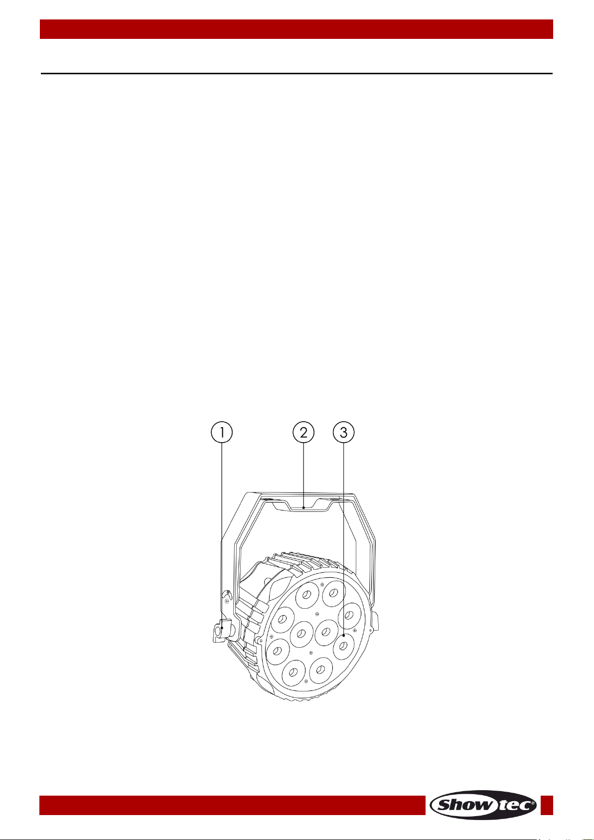
Frontside
Fig. 01
Description of the device
Features
The Powerspot 10SW brings the right white tone to your stage or venue. It is equipped with 10 pieces LED
which are built out of cool white, warm white and amber in one single chip ensuring a perfect white
balance. It is the ideal solution for small clubs and mobile DJs.
Smart White color control
Robust housing
Double bracket
Input voltage: 100-240V, 50/60Hz
Power consumption: 56W
DMX channels: 3, 6 or 7 channels
LCD display for easy setup
Light source: 10 x WW/CW/A High Power LEDs
Lux @2m: 4420 (Full output)
Control modes: Built-in Programs, Auto, Sound, Static dimmer, Master/Slave, DMX
Control protocol: DMX-512
Dimmer: 0-100%
Strobe: 0-20Hz
Beam Angle: 18°
Protection rate: IP-20
Housing: White aluminum
Cooling: Convection
Connections: Pro Power connectors (power in / power out), 3-pin XLR IN & OUT,
5-pin XLR IN & OUT
Dimensions: 265 x 113 x 295 mm (LxWxH)
Weight: 2,8 kg
01) Adjustment screw
02) Double mounting bracket
03) 10 x WW/CW/A High Power LEDs
7
Page 9
Ordercode: 42578
Powerspot 10 SW White
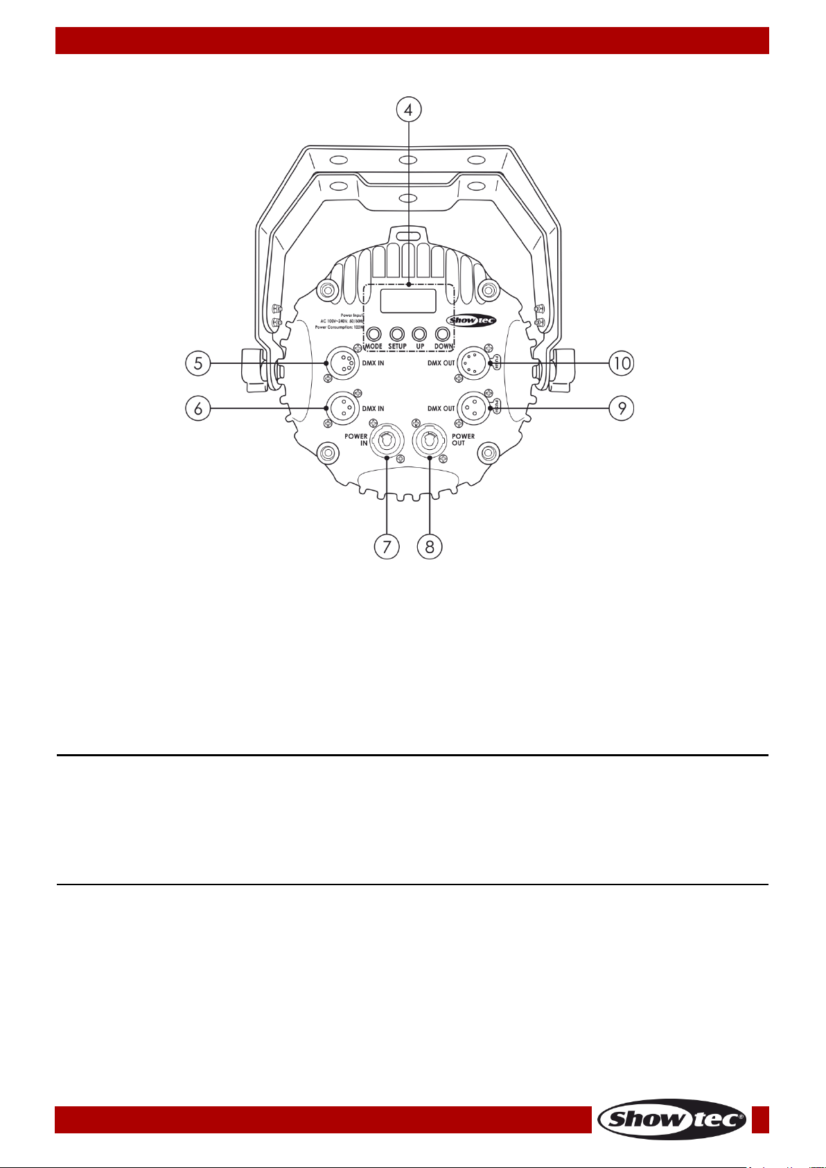
Backside
Fig. 02
04) LCD display + control buttons
05) 5-pin DMX signal connector IN
06) 3-pin DMX signal connector IN
07) Blue Pro Power connector 100-240V IN
08) White Pro Power connector 100-240V OUT
09) 3-pin DMX signal connector OUT
10) 5-pin DMX signal connector OUT
Installation
Remove all packing materials from the Powerspot 10 SW. Check if all foam and plastic padding is
removed. Connect all cables.
Do not supply power before the whole system is set up and connected properly.
Always disconnect from electric mains power supply before cleaning or servicing.
Damages caused by non-observance are not subject to warranty.
Set Up and Operation
Follow the directions below, as they pertain to your preferred operation mode.
Before plugging the unit in, always make sure that the power supply matches the product specification
voltage. Do not attempt to operate a 120V specification product on 230V power, or vice versa.
Connect the device to the main power supply.
8
Page 10
Ordercode: 42578
Powerspot 10 SW White
There are 6 modes:
• Auto run
• Built-in programs
• Static Color (dimmer)
• Sound-controlled
• Master/slave
• DMX-512 (3CH, 6CH or 7CH)
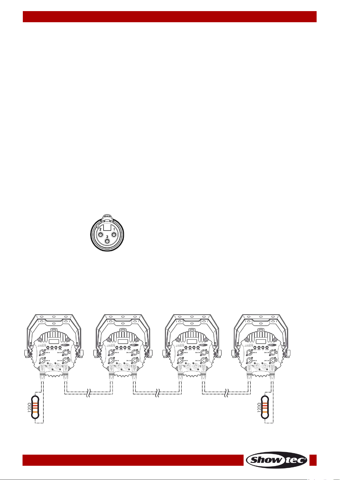
The pins:
1. Earth
2. Signal (-)
3. Signal (+)
Fig. 03
Control Modes
One Powerspot 10 SW (Auto Run Mode, Built-in programs and Static Color Mode)
01) Fasten the effect light to a firm trussing. Leave at least 0,5 meter on all sides for air circulation.
02) Plug the end of the electric mains power cord into a proper electric power supply socket.
03) When the Powerspot 10 SW is not connected with a DMX cable, it functions as a stand-alone
device. Please see pages 14 and 15 for more information about Auto Run Mode, the Built-in
programs and Static Color Mode.
One Powerspot 10 SW (Sound-controlled)
01) Fasten the effect light to a firm trussing. Leave at least 0,5 meter on all sides for air circulation.
02) Plug the end of the electric mains power cord into a proper electric power supply socket.
03) Turn on the music. If the device is set to sound-control, then the Powerspot will react to the beat of
the music. Please see page 15 for more information about the sound-control options.
Multiple Powerspots 10 SW (Master/Slave control)
01) Fasten the effect light onto firm trussing. Leave at least 0,5 meter on all sides for air circulation.
02) Always use a safety cable (ordercode 70140 / 70141).
03) Use a 3-p XLR cable to connect the Powerspots and other devices.
04) Link the units as shown in Fig. 03, connect a DMX signal cable from the first unit's DMX "out" socket to
the second unit's "in" socket. Repeat this process to link the second, third, and fourth units. You can
use the same functions on the master device as described on pages 14 and 15 (Auto run, Built-in
Programs, Static color). This means you can set your desired operation mode on the master device
and all slave devices will react the same as the master device.
Multiple Powerspots 10 SW (Master/Slave control)
9
Page 11
Ordercode: 42578
Powerspot 10 SW White
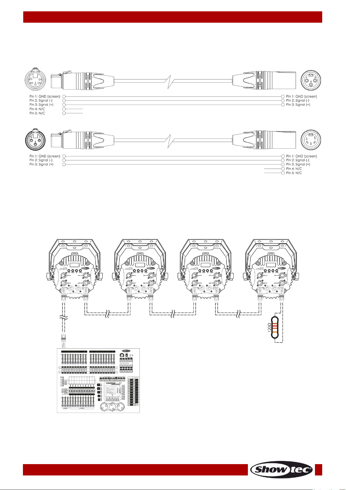
Multiple Powerspots 10 SW DMX Set Up
Fig. 04
Multiple Powerspots 10 SW (DMX Control)
01) Fasten the effect light to a firm trussing. Leave at least 0,5 meter on all sides for air circulation.
02) Always use a safety cable (ordercode 70140 / 70141).
03) Use a 3-pin XLR cable to connect the Powerspots and other devices.
04) Link the units as shown in Fig. 04. Connect the first unit's DMX "out" socket with the second unit's "in"
socket, using a DMX-signal cable. Repeat this process to link the second, third, and fourth units.
05) Supply electric power: Plug electric mains power cords into each unit's Pro Powercon socket, then
plug the other end of the mains power cord into proper electric power supply sockets, starting with
the first unit. Do not supply power before the whole system is set up and connected properly.
Note : Link all cables before connecting electric power
10
Page 12

Ordercode: 42578
Powerspot 10 SW White
Important:
Fixtures on a serial data link must be daisy-chained in a single line. To comply with the
EIA-485 standard, no more than 30 devices should be connected on one data link.
Connecting more than 30 fixtures on one serial data link without the use of a DMX optically
isolated splitter may result in deterioration of the digital DMX signal.
Maximum recommended DMX data link distance: 100 meters
Maximum recommended number of fixtures on a DMX data link: 30 fixtures
Maximum recommended number of fixtures on a power link: 8 @ 110V
Maximum recommended number of fixtures on a power link: 16 @ 240V
Fixture Linking
You will need a serial data link to run light shows of one or more fixtures using a DMX-512 controller or to
run synchronized shows of two or more fixtures set to a master/slave operating mode. The combined
number of channels required by all the fixtures on a serial data link determines the number of fixtures the
data link can support.
Data Cabling
To link fixtures together, you must obtain data cables. You can purchase DAP Audio certified DMX cables
directly from a dealer/distributor or construct your own cable. If you choose to create your own cable,
please use data-grade cables that can carry a high quality signal and are less prone to electromagnetic
interference.
DAP Audio DMX Data Cables
• DAP Audio Basic microphone cable for allround use. bal. XLR/M 3-pin > XLR/F 3-pin. Ordercode
FL01150 (1,5 m), FL013 (3 m), FL016 (6 m), FL0110 (10 m), FL0115 (15 m), FL0120 (20 m).
• DAP Audio X-type data cable XLR/M 3-pin > XLR/F 3-pin. Ordercode FLX0175 (0,75 m),
FLX01150 (1,5 m), FLX013 (3 m), FLX016 (6 m), FLX0110 (10 m).
• DAP Audio cable for the demanding user with exceptional audio-qualities and connector made by
Neutrik®. Ordercode FL71150 (1,5 m), FL713 (3 m), FL716 (6 m), FL7110 (10 m).
• DAP Audio cable for the demanding user with exceptional audio-qualities and connector made by
Neutrik®. Ordercode FL7275 (0,75 m), FL72150 (1,5 m), FL723 (3 m), FL726 (6 m), FL7210 (10 m).
• DAP Audio 110 Ohm cable with digital signal transmission. Ordercode FL0975 (0,75 m),
FL09150 (1,5 m), FL093 (3 m), FL096 (6 m), FL0910 (10 m), FL0915 (15 m), FL0920 (20 m).
• DAP Audio DMX adapter: 3-pin/5-pin. Ordercode FLA30.
The Powerspot 10 SW can be operated with a controller in DMX mode or without the controller in standalone mode.
11
Page 13
Ordercode: 42578
Powerspot 10 SW White
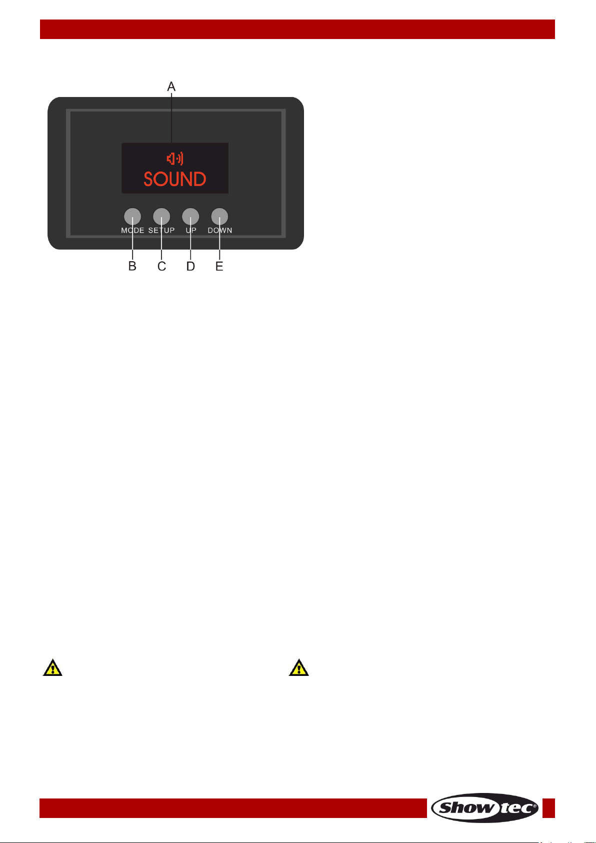
Control Panel
A) LCD display
B) MODE button
C) SETUP button
D) UP button
E) DOWN button
Fig. 05
Display Off after 5-30 seconds
Control Mode
The fixtures are individually addressed on a data-link and connected to the controller.
The fixtures respond to the DMX signal from the controller. (When you select the DMX address and save it,
the controller will display the saved DMX address, next time.)
DMX Addressing
The control panel on the back side of the device allows you to assign DMX fixture addresses, which is the
first channel with which the Powerspot will respond to the controller.
Please note, when you use the controller, the unit has 7 channels.
When using multiple Powerspots, make sure you set the DMX addresses right.
Therefore, the DMX address of the first Powerspot should be 1(001); the DMX address of the second
Powerspot should be 1+7=8 (008); the DMX address of the third Powerspot should be 8+7=15 (015), etc.
Please, be sure that you do not have any overlapping channels in order to control each Powerspot
correctly. If two or more Powerpsots are addressed similarly, they will work similarly.
Controlling:
After having addressed all Powerspot fixtures, you may now start operating these via your lighting
controller.
Note: After switching on, the Powerspot will automatically detect whether DMX 512 data is received or
not. If there is no data received at the DMX-input, there will be no text “DMX in “ on the control panel
displayed.
If not, the problem may be:
• The XLR cable from the controller is not connected with the input of the Powerspot.
• The controller is switched off or defective, the cable or connector is detective, or the signal wires are
swapped in the input connector.
Note: It is necessary to insert an XLR termination plug (with 120 Ohm) in the last fixture in order to ensure
proper transmission on the DMX data link.
When no button is pressed for 05, 10, 20 or 30 seconds, the display will turn off.
You can set this time in the menu “Settings”, see page 16.
To light up the display, you have to press the MODE, SETUP, UP or DOWN button.
Once you have pressed the button, the display will light up.
12
Page 14
Ordercode: 42578
Powerspot 10 SW White
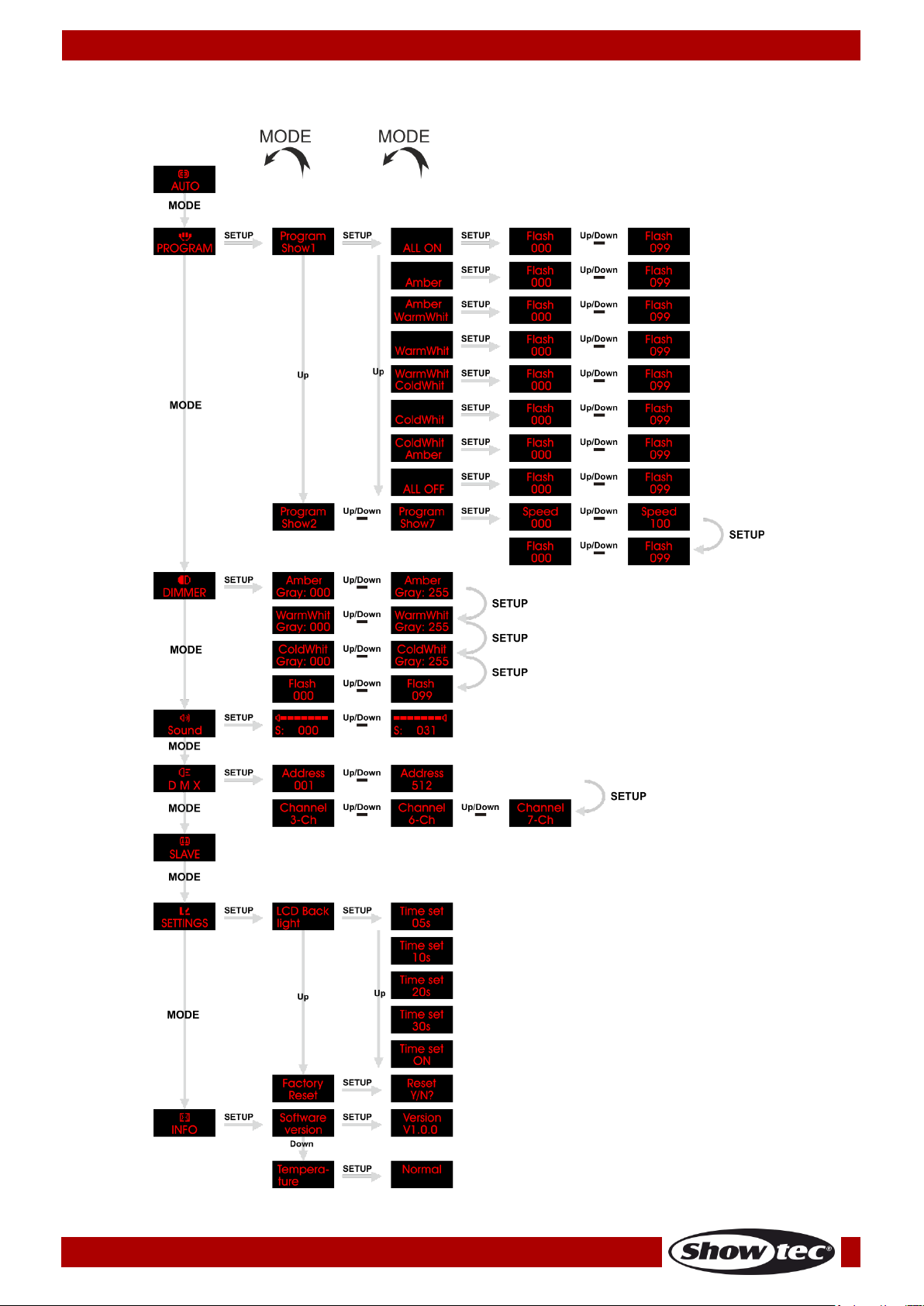
Menu Overview
13
Page 15
Ordercode: 42578
Powerspot 10 SW White
Auto run
Built in programs
Static Color Mode
Sound-controlled Mode
DMX address / DMX configuration
Slave mode
Settings
Info
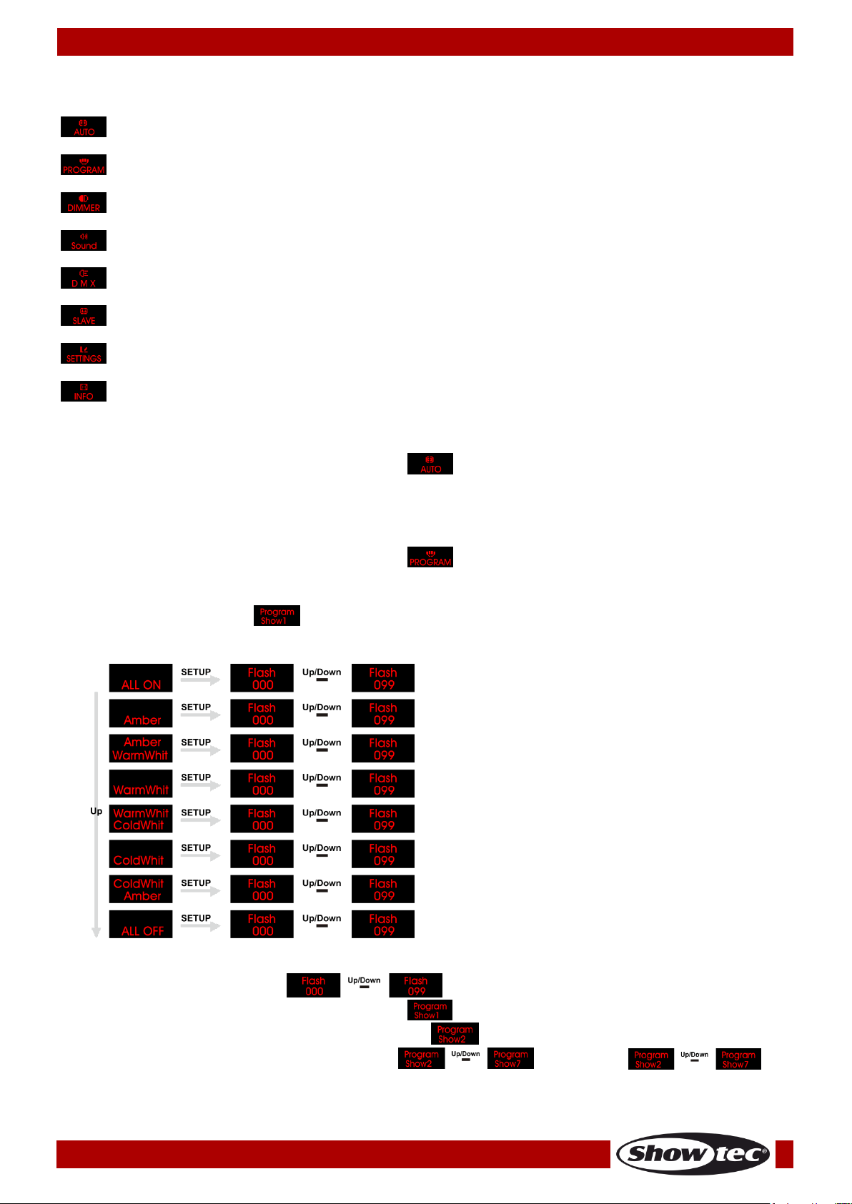
Main Menu Options
Auto Run Mode
With this menu you can start the Auto Run program of the Powerspot 10 SW.
01) Press the MODE button until the display shows .
02) The Powerspot will start immediately the Auto Run program.
Built-in Programs
With this menu you can choose a built-in program.
01) Press the MODE button until the display shows .
02) Press the SETUP button to open this menu.
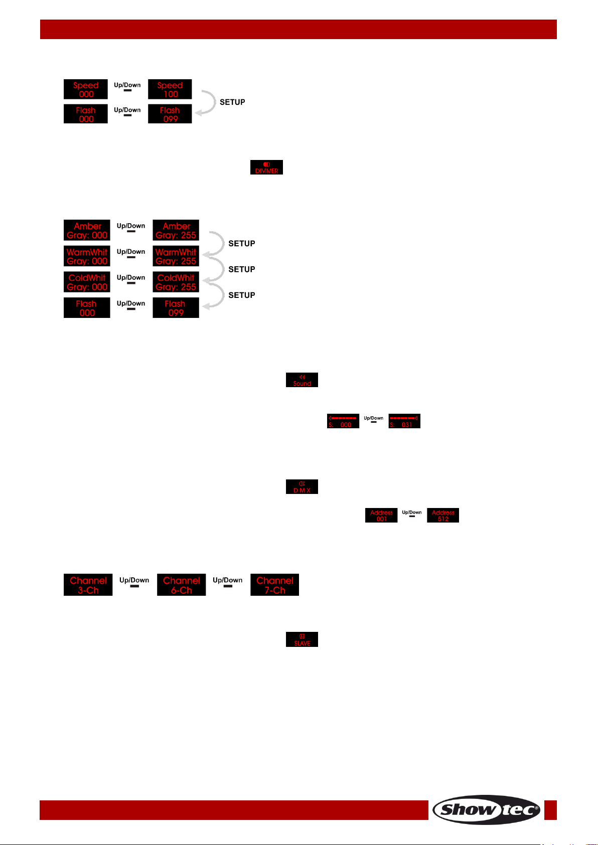
03) You can use the UP/DOWN buttons to scroll through the 8 built-in programs.
04) When you select menu , you can choose between a variety of color settings. Press SETUP to
enter and choose one color setting with the UP/DOWN buttons.
05) Press the SETUP button again to open the next menu. You can set the Flash frequency with the
UP/DOWN buttons between .
06) Press the MODE button until the display shows .
07) Use the UP/DOWN buttons until the display shows .
Use the UP/DOWN buttons to scroll between . In the menu ,
you can switch between the Flash frequency and the Program Running Speed by pressing the SETUP
button.
14
Page 16
Ordercode: 42578
Powerspot 10 SW White
Speed from 00-100
Flash Frequency from 00-99
Gradual adjustment Amber (0-255)
Gradual adjustment Warm white (0-255)
Gradual adjustment Cool white (0-255)
Frequency strobe (0-99)
08) Use the UP/DOWN buttons to change the values.
Static Color control
With this menu you can manually set a desired color.
01) Press the MODE until the display shows .
02) Press the SETUP button to open this menu.
03) You can use the SETUP button to scroll through 3 color options and also set the strobe frequency.
04) Use the UP/DOWN buttons to change the values.
You can combine Amber, Warm white and Cool white to create an infinite range of white colors.
Sound control mode
With this menu you can set the sensitivity of the sound mode.
01) Press the MODE button until the display shows .
02) Press the SETUP button to open this menu.
03) Use the UP/DOWN buttons to change the values.
Set the sensitivity of the sound control mode between .
04) Turn on the music and the Powerspot 10 SW will react to the beat of the music
DMX Addressing/ DMX configuration
With this menu you can set the DMX address and choose a DMX configuration.
01) Press the MODE button until the display shows .
02) Press the SETUP button to open this menu. You can choose 512 different DMX addresses.
03) Use the UP/DOWN buttons to select the required address from .
Once you have set the desired DMX address, you can also choose the desired DMX Mode.
04) Press the SETUP button again to choose one of the 3 different DMX Modes. Use the UP/DOWN buttons
to select 3, 6 or 7 channels.
Slave Mode
With this menu you can set the device as a Slave.
01) Press the MODE button until the display shows .
If the device has not been set to slave, it is automatically classified as a master device. All slave
devices will follow the master movement. If the device has been set to slave, it will react the same as
its master device.
15
Page 17
Ordercode: 42578
Powerspot 10 SW White
Settings
With this menu you can set various options.
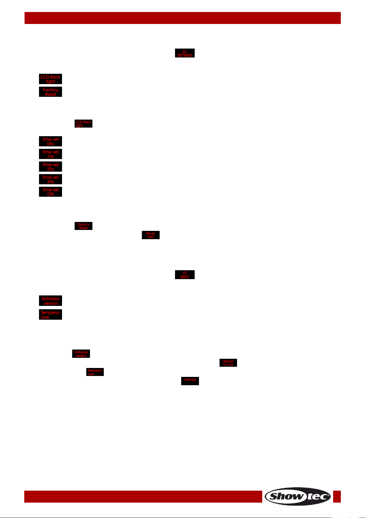
01) Press the MODE button until the display shows .
02) Press the SETUP button to open this menu.
03) Use the UP/DOWN buttons to choose between the 2 options.
04) Press the SETUP button to open one of the 2 options.
05) With option you can set the desired LCD backlight time.
06) Choose with the UP/DOWN buttons the desired time or if you choose “ON”, the display will
continuously light up.
07) With option you can reset the device to the factory settings.
08) Press the SETUP button to proceed .
09) Press SETUP again to confirm. The fixture will reset and start up in the Auto Run mode.
Info
With this menu you can see various info of the fixture.
01) Press the MODE button until the display shows .
02) Press the SETUP button to open this menu.
03) Use the UP/DOWN buttons to choose between the current software version and the current
temperature.
04) Press the SETUP button to open one of the 2 options.
05) The option is for showing the software version of the fixture.
06) Press the SETUP button and you can see the software version .
07) With the option you can see if the temperature of the fixture is too high or not.
08) Press the SETUP button and the display will show if the fixture has a normal temperature.
09) If the temperature of the fixture is too high (the fixture will give a warning error), you’ll have to switch
off the fixture.
16
Page 18
Ordercode: 42578
Powerspot 10 SW White
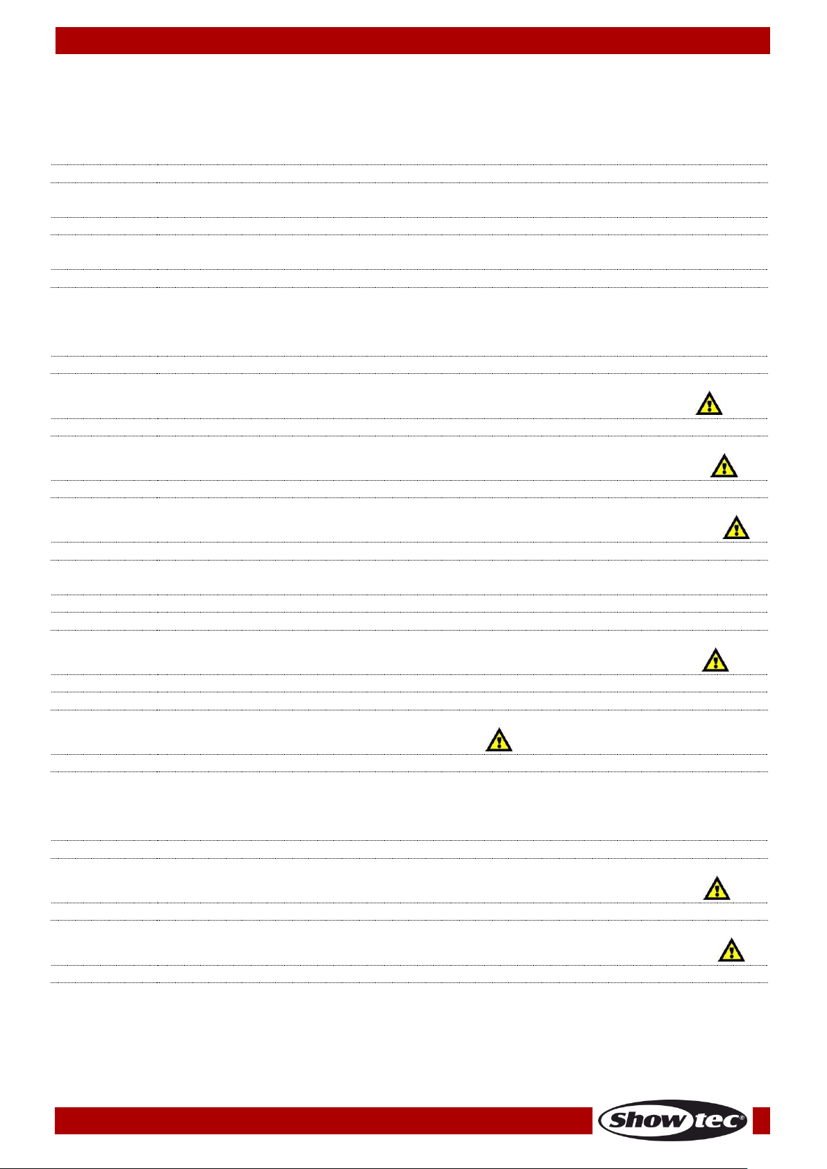
Channel 1 – Amber Dimmer intensity
0-255
Amber from 0-100%
Channel 2 – Warm White Dimmer intensity
0-255
Warm White from 0-100%
Channel 3 – Cool White Dimmer intensity
0-255
Cool White from 0-100%
Channel 1 – Master Dimmer intensity
0-255
From dark to brightest 0-100%
Channel 2 – Amber Dimmer intensity (CH1 must be set between 001-255 and CH5 between 0-9 )
0-255
Amber from 0-100%
Channel 3 – Warm White Dimmer intensity (CH1 must be set between 001-255 and CH5 between 0-9 )
0-255
Warm White from 0-100%
Channel 4 – Cool White Dimmer intensity (CH1 must be set between 001-255 and CH5 between 0-9 )
0-255
Cool White from 0-100%
Channel 5 – Dimming/Sound mode
0-9
Dimming mode
10-255
Sound mode
Channel 6 – Strobe (CH1 and CH2, CH3 or CH4 must be between 001-255 and CH5 between 0-9 )
0-9
No function
10-255
Strobe flash frequency, from slow to fast (0-20 Hz)
Channel 6 – Sound sensitivity (CH5 must be set between 10-255 )
0-255
Gradual adjustment Sensitivity, from 1-100%
Channel 1 – Master Dimmer intensity
0-255
From dark to brightest 0-100%
Channel 2 – Amber Dimmer intensity (CH1 must be set between 001-255 and CH5 between 0-24 )
0-255
Amber from 0-100%
Channel 3 – Warm White Dimmer intensity (CH1 must be set between 001-255 and CH5 between 0-24 )
0-255
Warm White from 0-100%
DMX Channels
3 channels
6 channels
7 channels
17
Page 19
Ordercode: 42578
Powerspot 10 SW White
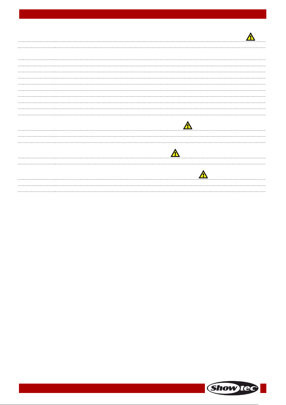
Channel 4 – Cool White Dimmer intensity (CH1 must be set between 001-255 and CH5 between 0-24 )
0-255
Cool White from 0-100%
Channel 5 – Dimming/Program/Sound mode
0-24
Dimming mode
25-49
Auto run
50-74
Built-in program 1
75-99
Built-in program 2
100-124
Built-in program 3
125-149
Built-in program 4
150-174
Built-in program 5
175-199
Built-in program 6
200-255
Sound mode
Channel 6 – Built-in program speed (CH5 must be set between 50-199 )
0-19
No function
20-255
Gradual speed adjustment, from slow to fast
Channel 6 – Sound sensitivity (CH5 must be set between 200-255 )
0-255
Gradual adjustment Sensitivity, from 1-100%
Channel 7 – Strobe (CH1 and CH2, CH3 or CH4 must be set between 001-255 )
0-9
No function
10-255
Strobe flash frequency, from slow to fast (0-20 Hz)
18
Page 20
Ordercode: 42578
Powerspot 10 SW White
Maintenance
The operator has to make sure that safety-related and machine-technical installations are to be
inspected by an expert after every year in the course of an acceptance test.
The operator has to make sure that safety-related and machine-technical installations are to be
inspected by a skilled person once a year.
The following points have to be considered during the inspection:
01) All screws used for installing the device or parts of the device have to be tightly connected and
must not be corroded.
02) There may not be any deformations on housings, fixations and installation spots.
03) Mechanically moving parts like axles, eyes and others may not show any traces of wearing.
04) The electric power supply cables must not show any damages or material fatigue.
The Powerspot 10 SW requires almost no maintenance. However, you should keep the unit clean.
Otherwise, the fixture’s light-output will be significantly reduced. Disconnect the mains power supply, and
then wipe the cover with a damp cloth. Do not immerse in liquid. Wipe lens clean with glass cleaner and
a soft cloth. Do not use alcohol or solvents.
The front lens will require weekly cleaning, as smoke-fluid tends to build up residues, reducing the lightoutput very quickly.
Keep connections clean. Disconnect electric power, and then wipe the DMX and audio connections
with a damp cloth. Make sure connections are thoroughly dry before linking equipment or supplying
electric power.
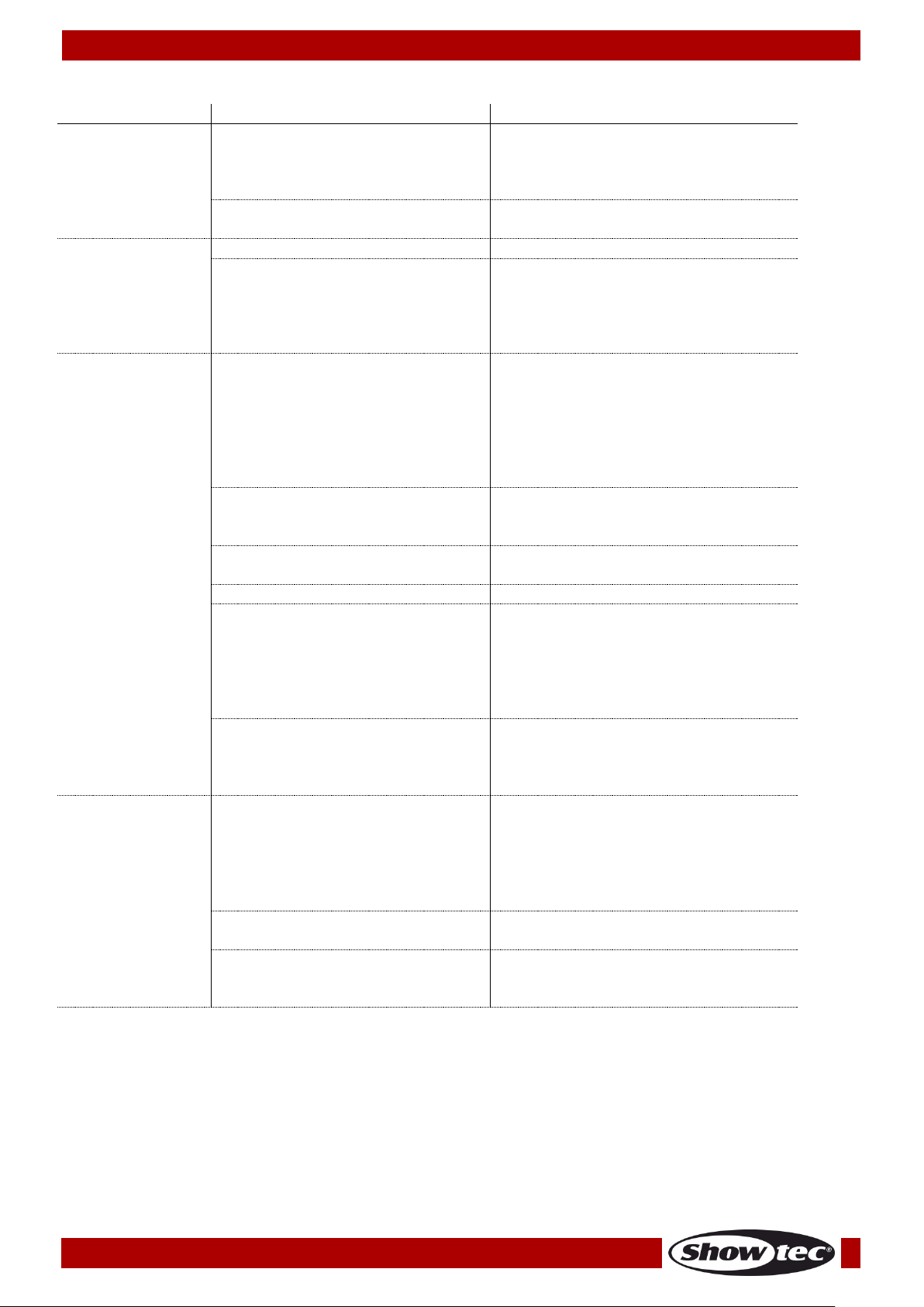
Troubleshooting
This troubleshooting guide is meant to help solve simple problems.
If a problem occurs, carry out the steps below in sequence until a solution is found. Once the unit
operates properly, do not carry out following steps.
No Light
If the light effect does not operate properly, refer servicing to a technician.
Suspect three potential problem areas as: the power supply, the LEDs, the internal fuse.
01) Power supply. Check that the unit is plugged into an appropriate power supply.
02) The LEDs. Return the Powerspot to your Showtec dealer.
03) The internal fuse. Return the Powerspot to your Showtec dealer.
04) If all of the above appears to be O.K., plug the unit in again.
05) If you are unable to determine the cause of the problem, do not open the Powerspot, as this may
damage the unit and the warranty will become void.
06) Return the device to your Showtec dealer.
No Response to DMX
Suspect the DMX cable or connectors, a controller malfunction, a light effect DMX card malfunction.
01) Check the DMX setting. Make sure that DMX addresses are correct.
02) Check the DMX cable: Unplug the unit; change the DMX cable; then reconnect to electrical power.
Try your DMX control again.
03) Determine whether the controller or light effect is at fault. Does the controller operate properly with
other DMX products? If not, take the controller in for repair. If so, take the DMX cable and the light
effect to a qualified technician.
19
Page 21
Ordercode: 42578
Powerspot 10 SW White
Problem
Probable cause(s)
Solution
One or more
fixtures do not
function at all
No power to the fixture
• Check if power is switched on and
cables are plugged in
Internal fuse blown
• Return the Powerspot to your
Showtec dealer
Fixtures reset
correctly, but all
respond
erratically or not
at all to the
controller
The controller is not connected.
• Connect controller.
3-pin XLR Out of the controller
does not match XLR Out of the first
fixture on the link (i.e. signal is
reversed)
• Install a phase reversing cable
between the controller and the
first fixture on the link
Fixtures reset
correctly, but
some respond
erratically or not
at all to the
controller
Poor data quality
• Check data quality. If much lower
than 100 percent, the problem
may be a bad data link
connection, poor quality or
broken cables, missing termination
plug, or a defective fixture
disturbing the link
Bad data link connection
• Inspect connections and cables.
Correct poor connections. Repair
or replace damaged cables
Data link not terminated with 120
Ohm termination plug
• Insert termination plug in output
jack of the last fixture on the link
Incorrect addressing of the fixtures
• Check address setting
One of the fixtures is defective and
disturbs data transmission on the
link
• Bypass one fixture at a time until
normal operation is restored:
unplug both connectors and
connect them directly together.
• Have the defective fixture
serviced by a qualified technician
3-pin XLR Out on the fixtures does
not match (pins 2 and 3 reversed)
• Install a phase-reversing cable
between the fixtures or swap pin 2
and 3 in the fixture that behaves
erratically
No light or lamp
cuts out
intermittently
Fixture is too hot
• Allow the fixture to cool down
• Clean the fan
• Make sure air vents in control
panel and the front lens are not
blocked
• Turn up the air conditioning
LEDs damaged
• Disconnect the fixture and return it
to your dealer
The power supply settings do not
match local AC voltage and
frequency
• Disconnect fixture. Check settings
and correct if necessary
20
Page 22
Ordercode: 42578
Powerspot 10 SW White
Model:
Showtec Powerspot 10 SW
Input Voltage:
100-240 VAC, 50/60Hz
Power consumption:
56W (full output)
DMX linking:
30 pcs
Power linking:
16 pcs
Protection rate:
IP-20
Dimensions:
265 x 113 x 295 mm (LxWxH)
Weight:
2,8 kg
Operating and Programming:
Signal pin OUT:
Pin 1 (earth), pin 2 (-), pin 3 (+)
DMX Mode:
3, 6 or 7 channels
Signal input:
3-pin + 5-pin DMX IN
Signal output:
3-pin + 5-pin DMX OUT
Electro-mechanical effects:
LED Quantity:
10 x WW/CW/A High Power LED
Lux @2m:
4420 Lux (Full output)
Beam angle:
18°
Dimmer:
0-100%
Strobe:
0-20Hz
Housing:
White aluminum
DMX-control:
via standard DMX-controller
On Board:
LCD display for easy setup
Control:
Built-in Programs, Auto, Sound, Static dimmer,
Master/Slave, DMX
Connections:
Blue + White Pro Power connector (IN/OUT)
Cooling:
Convection
Max. ambient temperature ta:
40°C
Max. housing temperature tB:
80°C
Minimum distance:
Minimum distance from flammable surfaces:
0,5 m
Minimum distance to lighted object:
1 m
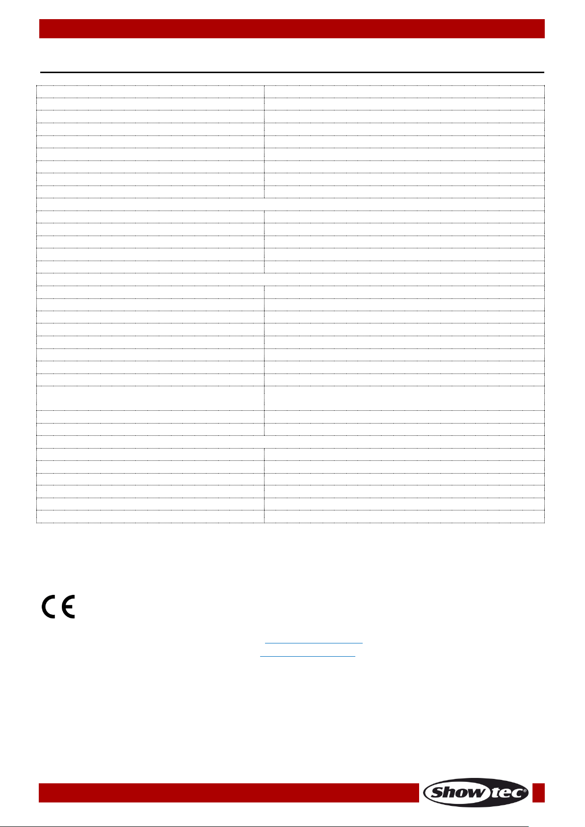
Product Specifications
Design and product specifications are subject to change without prior notice.
21
Website: www.Showtec.info
Email: [email protected]
Page 23
Ordercode: 42578
Powerspot 10 SW White
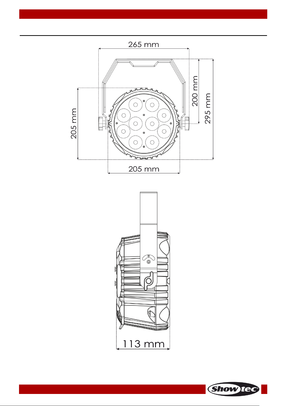
Dimensions
22
Page 24

©2016 Showtec
 Loading...