

Page 1

0
All rights reserved.
The informatio n in this document is subject t o change without not ic e.
Publish statement
Thank you for purchasing this series UPS.
This series UPS is an intelligent, three phase in Three phase out, high frequency online
UPS designed by our R&D team who is with years of designing experi enc es on UPS.
With excellent elec trical performance, perfect intelligent monit oring and network
functions, smar t appearance, complying with EMC and safety standards, The UPS
meets the worl d’s advanced level.
Read this manual c ar efully before ins tallation
This manual provides technica l support to the operator of the equipment.
Page 2

1
Contents
1.Safety............................................................................................................................................................ 2
1.1 Safety notes ....................................................................................................................................... 2
1.2 Symbols used in this guide............................................................................................................ 2
2.Main Features............................................................................................................................................. 3
2.1 Summarization................................................................................................................................... 3
2.2 Functions and Features .................................................................................................................. 3
3.Installation................................................................................................................................................... 4
3.1 Unpack checking .............................................................................................................................. 4
3.2 Cabinet Outl o ok ................................................................................................................................4
3.4 LCD control panel ............................................................................................................................. 5
3.5 Installation notes............................................................................................................................... 6
3.6 External Protective Devices ............................................................................................................ 7
3.7 Power
Cables
..................................................................................................................................... 7
3.8 Power cable connect ........................................................................................................................ 8
3.9 Battery connection ........................................................................................................................... 9
3.10 UPS Multi-Module Installation ................................................................................................. 10
3.11 Computer access .......................................................................................................................... 11
4.Operation................................................................................................................................................... 13
4.1 Operation Modes ............................................................................................................................. 13
4.2 Turn on/off UPS ............................................................................................................................... 14
4.3 The LCD Display.............................................................................................................................. 19
4.4 Parameters setting ......................................................................................................................... 24
4.5 Display Messages/Troubleshooting........................................................................................... 29
4.6 Options .............................................................................................................................................. 31
Appendix 1 Specifications .......................................................................................................................... 33
Appendix 2 Problems and Solution .......................................................................................................... 34
Appendix 3 USB communication port definition .................................................................................. 36
Appendix 4 RS485 communication port definition............................................................................... 37
Appendix 5 BAT_T communication port definition .............................................................................. 38
Appendix 6 Drycontact port communication port definition ............................................................. 39
Appendix 7 REPO instruction .................................................................................................................... 40
Page 3

2
1.Safety
Important saf ety instructions – Save these instructi ons
There exists dangerous voltage and high temperature inside the UPS. During the
installation, operation and maintenance, please abide the local s afet y inst ruct ions and relative
laws, otherwise it will result in personnel injury or equipment damage. Saf e t y inst ruct i o ns in this
manual act as a supplementary for the local safety instructions. Our company will not assume
the liability that caused by d isobeying safety instructions.
1.1 Safety notes
1. Even no connection with utility power, 220/230/240VAC voltage may still exist at UPS outlet!
2. For the sake of hum an being safety, please well earth the UPS before starting it.
3.Don’t open or damage battery, for the liquid spilled from the battery is strongly poisonous and
do harmful to body!
4.Please avoid short circuit between anode and cathode of battery, otherwise, it will cause
spark or fire!
5.Don’t disassemble t he UPS cover, or there may be an electric shock!
6.Check if there exists high voltage before touching the battery
7.Working environment and storage way will affect the lifetime and reliability of the UPS. Avoid
the UPS from working under following environment for long time
◆ Area where the humidity and temperature is out of the specified range(temperature 0
to 40℃, relative humidity 5%-95%)
◆ Direct sunlight or location nearby heat
◆ Vibration Area with possibility to get the UPS crashed.
◆ Area with erosive gas, flammable gas, excessive dust, etc
8.Keep ventilations in good conditions otherwise the components inside the UPS will be
over-heated whi ch may affect the life of the UPS.
1.2 Symbols used in this guide
WARNING!
Risk of electric shock
CAUTION!
Read this information to avoid equipment damage
Page 4

3
2.1 Summarization
2.Main Features
This series UPS is a kind of three-in-three-o ut hig h frequency online UPS, it provides three
specifications: The 10kVA/15kVA and 20kVA. The products are modularized and adopt the N+X
redundancy. It can flexibly increase the number of the UPS modules according to the load
capacity which is convenient for flexible allocation and gradually inve s t m e nt.
The UPS can solve most of the power supply problems, such as blackout, over-voltage,
under-voltage, voltage sudden drop, oscillati ng of decreasing extent, high voltage pulse, voltage
fluctuation, surg e, inrush current , harmonic distortion (THD), noise interference, frequency
fluctuation, etc..
This UPS can be applied to different applications from computer device, automatic equipment,
communicat ion system to industry e quipment.
2.2 Functions and
Features
◆3Phase In/3Phase Out UPS
It is 3Phase In/3Phase Out high-density UPS system, of which input current is kept in balance.
No unbalance problem might occur.
◆Digital Control
This series UPS is controlled by Digital Signal Processor(DSP); ehance, it increases
reliability, performance, self-proteciton, self-diagnostics and so on.
◆Battery Configurable from 16 blocks to 20 blocks
The battery voltage of this series UPS can be configured at 16 blocks, 18 blocks or 20 blocks
accord ing t o your convenience.
◆Charging Current is configurable
Via setting tool, the user may set the capacity of the batteries as well as reasonable charging
current as well as maximum charging current . Constant voltage mode, constant current mode or
floating mode can be switc hed automatically and smoothly.
◆Intelligent Charging Method
The series UPS adopts advanced three-stage charging method—
1
st
stage: high current constant current charging
to guarantee to charge back to 90%;
2
nd
-stage: Constant Voltage
In order to vitalize battery and make sure batteries are fully charged
3
rd
stage: floating mode.
With this 3-stage charging method, it extends the life of the batteries and guarantees fast charging.
Page 5
4
◆LCD Display
With LCD plus LED displays, the user may easily get UPS status and its operational
parameters, such as input/output voltage, frequency & load%, battery % and ambient
temperature, etc..
◆Intelligent Monitoring Function
Via optional SNMP Card, you may remotely control and monitor the UPS.
◆EPO Function
The series UPS may be completely shut off when the EPO is pressed. REPO
function(Remote EPO) is also available in this series UPS.
3.1 Unpack checking
3.Installation
1.Don’t lean the UPS when moving it out fr om the packaging
2.Check the appearance to see if the UPS is damaged or not duri ng the transportation, do not
switch on the U PS if any damage found. Please contact the dealer right away.
3.Check the accessories accor ding to the packing list and contact the dealer in case of missing
parts.
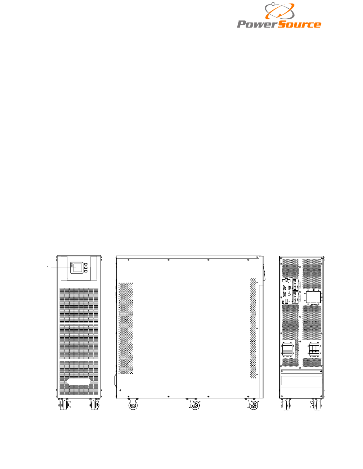
3.2 Cabinet Outlook
Front View Side View Rear View
Page 6
5
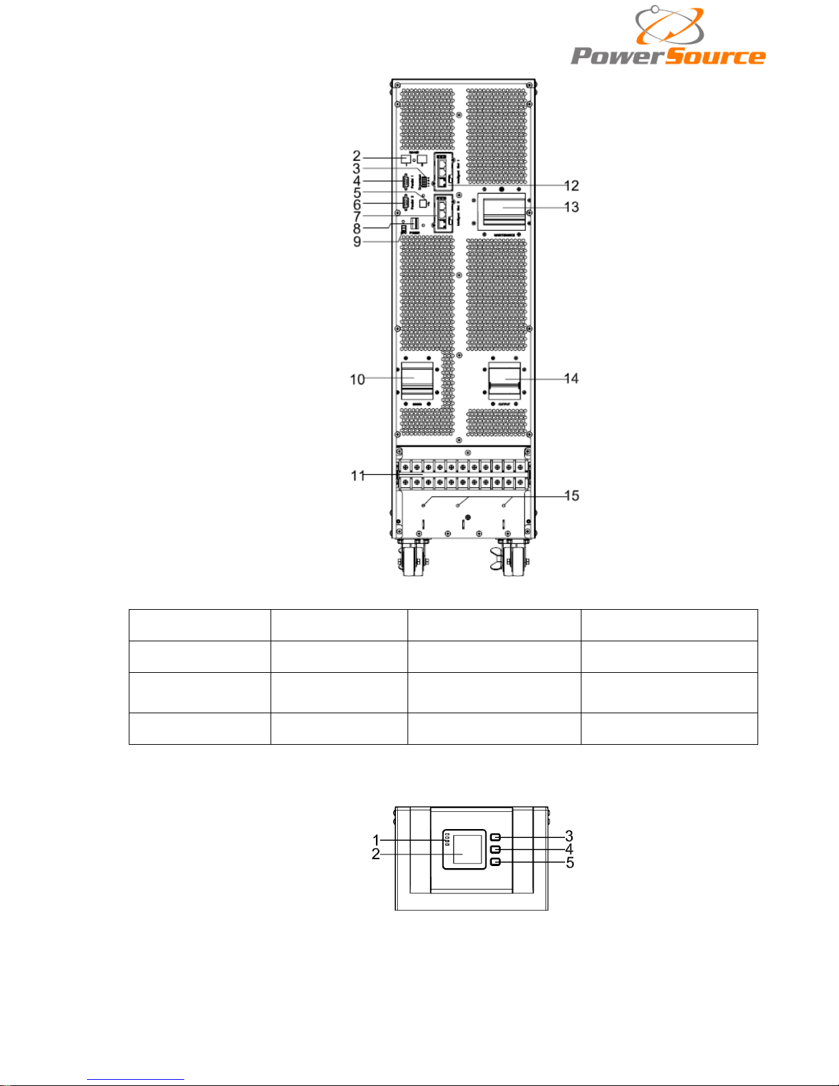
Rear View(terminal block without cover)
(1) LCD panel
(2) RS485 port
(3) Drycontac t port
(4) Par allel port 1
(5) USB port
(6) Par allel port 2
(7) Intelligent Solt 2
(SNMP card/ Relay card)
(8) Power Switch
(9) REPO port
(10) I/P Switch
(11)Terminal b lock for
Input, output & battery
(12)Intelligent Solt 1
(SNMP card/ Relay card)
(13) Maintenance
switch & its cover
(14) O/P Switch
(15) GND
3.4 LCD control panel
LCD control panel introduction
(1)LED(from top to bottom: “alarm”, “bypass”, “battery”, “inverter”) (2)LCD display(3)
scroll button (4)Off button (5)On button(battery cold start switch)
Page 7
6
3.5 Installation notes
Note: Consider for the convenience of operation and maintenance, the space in
front and back of the cabinet should be left at least 100cm and 80cm respectively when
installing the cab inet .
◆Please place the UPS in a clean, stable environment, avoid the vibration, dust, humidity,
flammable gas and liquid, corrosive. To avoid from high room temperature, a system of room
extractor fans is recommended to be installed. Optional air filters are available if the UPS operates
in a dusty environment.
◆The environment temperature around UPS should keep in a range of 0℃~40℃. If the
environment temperature exceeds 40℃, the rated load capacity should be reduced by 12% per
5℃. The max temperature can't be hi gher than 50℃.
◆If the UPS is dismantled under low temperature, it might be in a condensing condition.The
UPS can't be installed unless the internal and external of the equipment is fully dry. Otherwise,
there will be in danger of electric shock.
◆Batteries should be mounted in an environment where the temperature is within the required
specs. Temperature is a major factor in determining battery life and capacity. In a normal
installation, the battery temperature is maintained between 15°C and 25°C. Keep batteries away
fr om heat sourc es or main air ventilation area, etc.
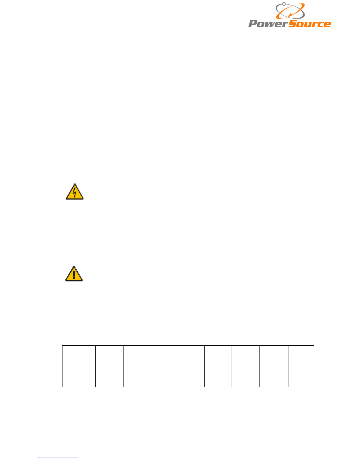
WARNING!
Typical battery performance data are quoted for an operating
temperature between 20°C and 25°C. Operating it above this range will
reduce the battery life while operation below this range will reduce the
battery capacity.
◆Should the equipment not be installed immediately it must be stored in a room so as to
protect it against excessive humidity and or heat s ources。
CAUTION!
An unused battery must be recharged every 6months Temporarily
connecting the UPS to a suitable AC supply mains and activating it for
the time required for recharging the batteries.
◆The highest altitude that UPS may work normally with full load is 1500 m eters. The load
capacity should be reduced when this UPS is installed in place whose altitude is higher than 1500
meters, shown as the followi ng table:
(Load coefficient equals max load in high altitude place divided by nominal power of the
UPS)
Altitude
(m)
1500
2000
2500
3000
3500
4000
4500
5000
Load
coefficient
100%
95%
90%
85%
80%
75%
70%
65%
◆The UPS cooling is depending on fan, so it should be kept in good air ventilation area.
There are many ventilation holes on the front and rear, so they should not be blocked by any exotic
obstacles.
Page 8
7
3.6 External Protective Devices
For safety reasons, it is necessary to install, external circuit breaker at the input A.C. supply and
the battery. This chapter provides guidelines for qualified installers that must have the knowledge of
local wir ing practices for the equipment to be installed.
◆External Battery
The UPS and its associated batteries are protected against the effect of over-current
through a DC compatible thermo-magne tic circuit-breaker (o r a set of fuses) located close to
the battery.
◆UPS Output
Any external distribution board used f or load distribution shall be fitted with protective
devices that may avoid the risk of UPS overloaded.
◆Over-current
Protection device shall be installed at the distribution panel of the incoming main supply. It
may identify the power cables current capacity as well as the overload capac ity of the system .
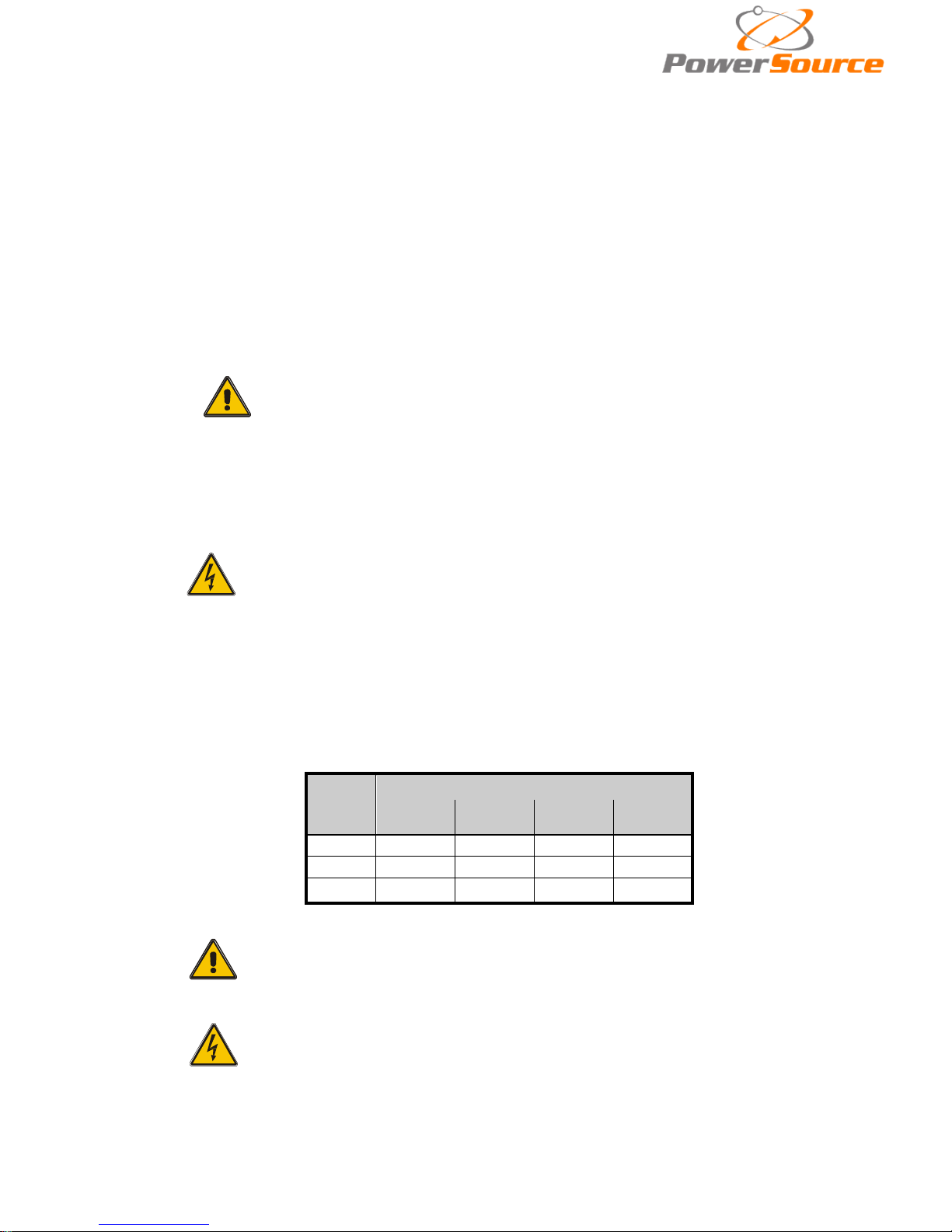
CAUTION !
Select a thermo magnetic circuit-breaker with an IEC 60947-2 trip
curve C (normal) for 125% of the current as listed below.
3.7 Power
Cables
◆The cable design shall comply with the voltages and currents provided in this section, Kindly
follow local wiring prac tices and take into consideration t he environmental co nditio ns (tem perat ure
and physical support media)
.
WARNING!
Upon starting.please ensure that you are aware of the location and
operation of the external isolators which are connected to the UPS
input/bypass supply of the mains distribution panel.check to see if
these supplies are electrically isolated.and post and necessary
warning signs to prevent any inadvertent operation .
◆For future expansion purpose, it is economical to install power cable according to the full rating
capacity initially. The diameter of cable is shown bellow:
UPS
cabinet
Cable Dimension
AC Input
2
AC
Output
2
DC Input
2
Grounding
2
10KVA
4 4
10
4
15KVA
6 6 16
6
20KVA
8 8 20
8
CAUTION!
Protective earth cable: Connect each cabinet to the main ground
system. For Grounding connection, follow the shortest route
possible。
WARNING!
Failure to follow adequate earthing procedures may result in
electromagnetic interference or in hazards involving electric shock
and fire
Page 9
8
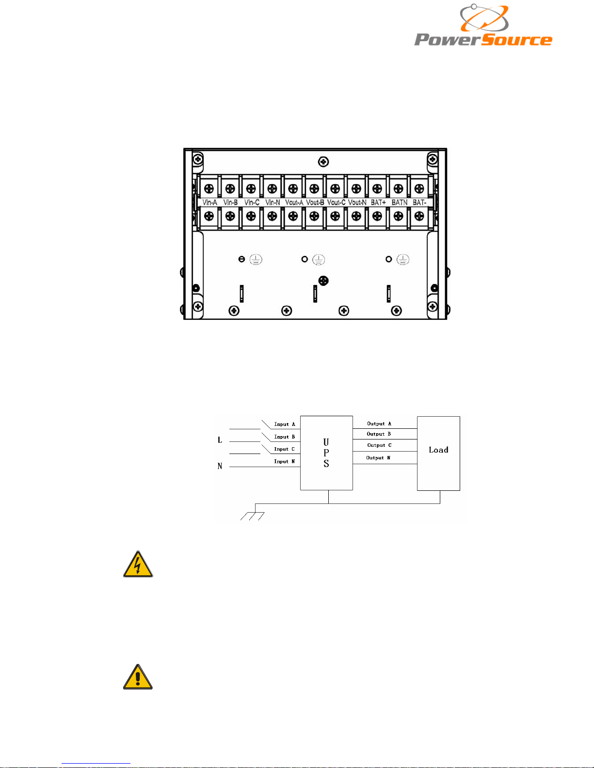
3.8 Power cable connect
Once the equipment has been finally positioned and secured, connect the power cables as
described in the following procedure.
Verify the UPS is totally isolated from its external power source and also all power isolators of the
UPS are open. Check to see if they are electrically isolated, and post any necessary warning signs to
prevent their inadvertent operation .
Remove the cover of terminals for wiring eas ily.
Te rmina l seq uence from left to right: Input phase A(L1), input phase B(L2), input phase
C(L3), input Neut ra l line, output phas e A(L1), output phase B(L2), output phase C(L3), output
Neutral line, battery positive, battery Neutral, battery negative. There are 3 connectors of
GROUND under the terminal block.
Choose appropriate power cable.(Refer to the table above)and pay attent ion to the
diameter of the connection terminal of the cable that s houl d be greater than or equal to that of
the connection poles;
WARNING!
If the load equipment is not ready to accept power on the
arrival of the commissioning engineer then ensure that the system
output cables are safely isolated at their ends
Connect the safety earth and any necessary bonding earth
cables to the copper earth screw located on the floor of the
equipment below the power connections. All cabinets in the UPS
must be grounded properly.
CAUTION!
The earthing and neutral bonding arrangement must be in
accordance with local and national codes of practice.
Page 10
9
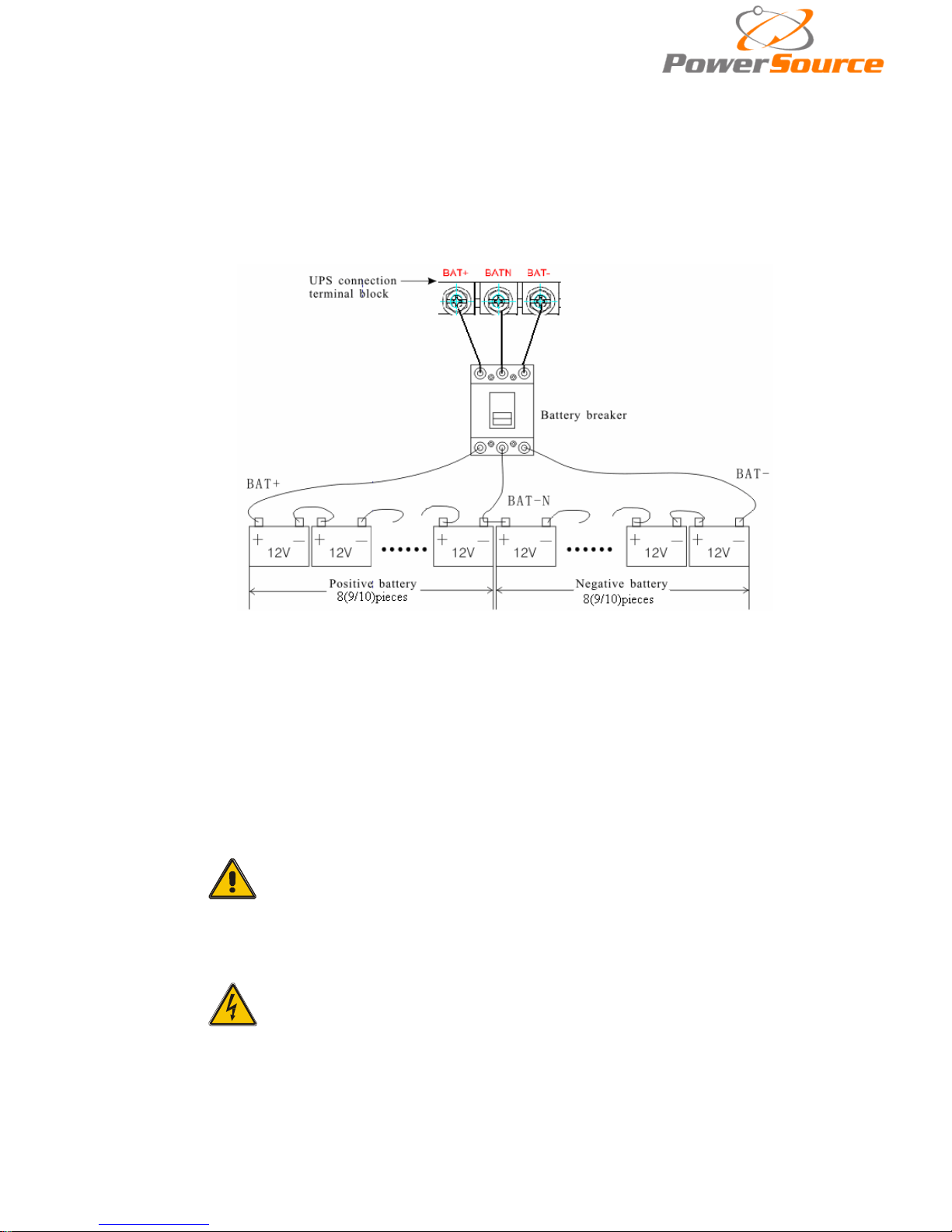
3.9 Battery connection
The UPS adopts positive and negative double battery framework, totally 16pcs(optional 18/20) in
series. A neutral cable is retrieved from the joint between the cathode of the 8
th (9th
/10 th) and the
anode of the 9
th
(10th/11 th) of the batteries. Then the neutral cable, the battery Positive and the
battery negative are connected with the UPS respectively. The battery sets between the Battery
anode and the neutral are called positive batteries and that between neutral and cathode are called
negative ones. The user can choose the capacit y a nd the numbers of the batteries according to their
desire.
External battery connections f or long-run units.
Note:
The BAT+ of the UPS connect poles is connected to the anode of the positive
battery, the BAT-N is connected to the cat hode of the positive battery and the anode
of the negative battery, the BAT- is connected to the cathode of the negative battery。
Factory sett in g of the long-run unit is battery quantity---16pcs, battery
capacity---12V65AH(charger current 9.75A). When connecting 18/20 batteries, please
re-set desired battery quantity and its capacity after UPS starts at AC mode. Charger
current could be adjusted automatically according t o batt er y capacity selected. All
related setti ngs c an be done through LCD panel or monitoring software
CAUTION!
Ensure correct polarity battery string series connection. i.e.
inter-tier and inter block connections are from (+) to (-)terminals.
Don’t mix batteries with different capacity or different brands, or
even mix up new and old batteries, either.
WARNING!
Ensure correct polarity of string end connections to the Battery
Circuit Breaker and from the Battery Circuit Breaker to the UPS
terminals i.e. (+) to (+) / (-) to (-) but disconnect one or more
battery cell links in each tier. Do not reconnect these links and do
not close the battery circuit breaker unless authorized by the
commissioning engineer.
Page 11
10
3.10 UPS Multi-Module Installation
The basic installation procedure of a parallel system comprising of two or more UPS modules is
the same as that of si ngle module system. The foll owing sections introduc e the installation
procedures specified to the parallel system.
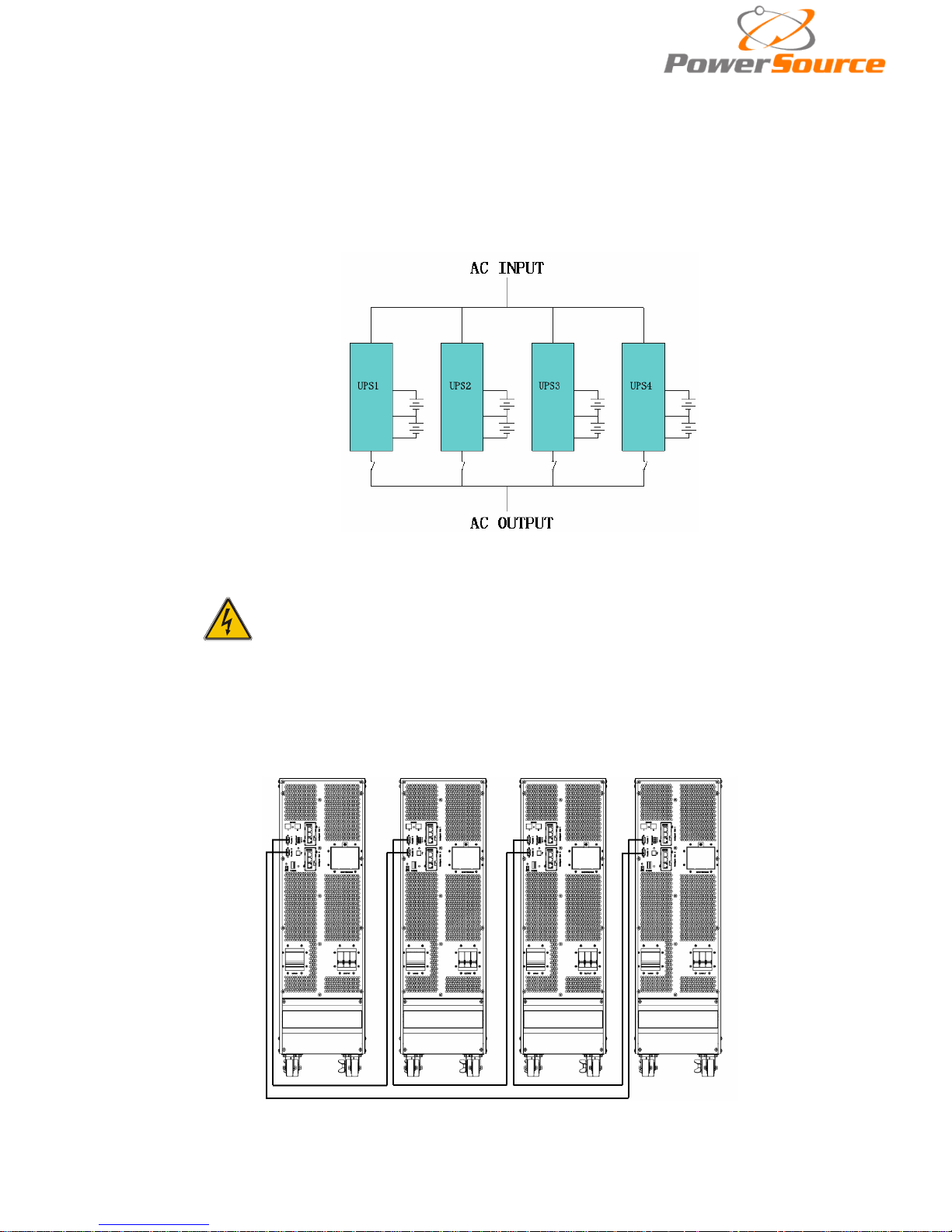
3.10.1 Cabinet installation
Connect all the UPSes needed to be put into parallel system as below picture.
Make sure each UPS input breaker is in “off” position and there is no any output from each
UPS connected. Battery groups can be connected separately or in parallel, which means the
system itself provides both separate battery and comman batt ery.
WARNING!
Make sure the N、A(L1)、B(L2)、C(L3)lines are correct, and
grouding is well connected.
3.10.2 Parallel cable installation
Shielded and double insulated c ontrol c ables available m us t be i nterconnect ed in a r ing
configuration between UPS units as shown below. T he para llel control board is m ounted on
each UPS module units. The ring conf iguration ensur es hi gh reliabi l ity of the control.
Page 12
11
3.10.3 Requirement for the parallel system
A group of paralleled modules behave as one large UPS system but with the advantage of
presenting higher reliability. In order to assure that all modules are equally utilized and comply
with relevant wiring rules, please follow the requirements below:
1) All UPS modules must be of the same rat ing and be connected to the same bypass
source.
2) The outputs of all the UPS modules must be connected to a common output bus.
3) The length and specification of power cables including the bypass input cables and the UPS
output cables should be the same. This facilitates load sharing when operating in bypass
mode.
3.11 Computer access
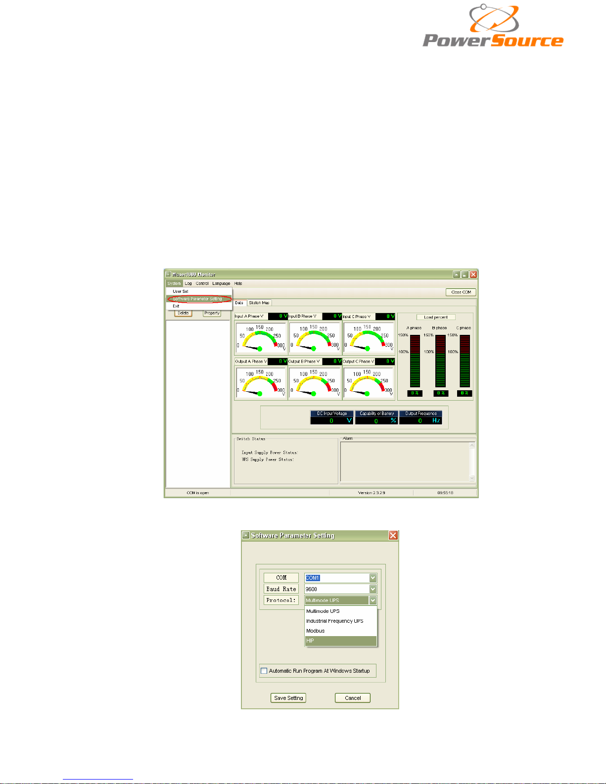
◆One end of a USB cable connect to the computer, the other end connect to the USB port on
the UPS.
◆Open the software Muser4000, click “system ” button .
◆A window of “Software Parameter Setting” comes out as below, COM choose according to the
UPS , baud rate choose 9600, protocol choose “HIP”, the n save this setting.
Page 13
12
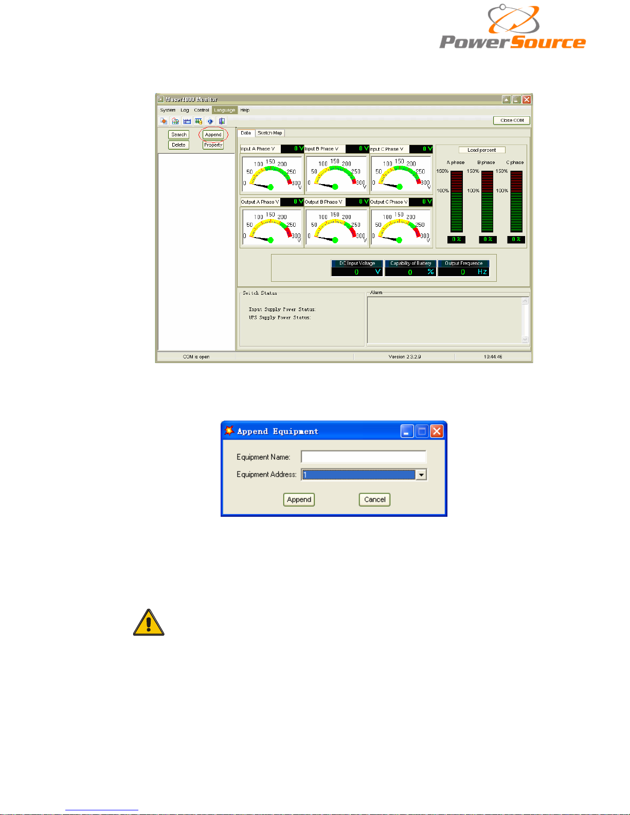
◆On the main page of Muser4000, click the button of “Append”, then goes to a window of
“Append equipment”.
◆Put the UPS nam e into “Equipment N ame”, and UPS’ ID address into “Equipment address”.
◆Click the butt on “Append”, then the connect ion between UPS & comp uter is accomplished.
CAUTION!
When the UPS worked on inverter. If you want to use PC to set the
output voltage and frequency. Must shut down the inverter first
Page 14

13
4.Operation
4.1 Operation Modes
The UPS is a double-conversion on-line UPS that may operate in the following alternative
modes:
◆Normal mode
The rectifier/charger derives power from the A C Mai ns and supplies DC power t o the inverter
while floating and boosting charge the battery simultaneously. Then, the inverter converts the DC
power to AC and supplies to the load.
◆Battery mode (Stored Energy Mode)
If the AC mains input power fails, the inverter, which obtains power from the battery, supplies the
critical AC load. There is no power interruption to the critical load. The UPS will automatically return to
Normal Mode when AC recovers.
◆Bypass mode
If the inverter is out of order, or if overload occurs, the static transfer switch will be act ivated to
transfer the load from the inverter supply to bypass supply without interruption to the critical load. In
the event that the inverter output is not synchronized with the bypass AC source, the static switch will
perform a transfer of the load from the inverter to the bypass with power interruption to the critical AC
load. This is to avoid paralleling of unsynchronized AC sources. This interruption is programmable
but typically set to be less than an electr ical cycle e.g. less than 15ms (50Hz) or less than 13.33ms
(60Hz).
◆ECO Mode
When the UPS is at AC Mode and the requirement to the load is not cr it ic a l, the UPS can be set
at ECO mode in order to increase the efficiency of the power supplied. At ECO mode, the UPS
works at Line-interactive mode, so the UPS will transfer to bypass supply. When the AC is out of
set window, the UPS will transfer from bypass to Inverter and supplies power from the battery,
the n the LCD shows all related information on the screen.
◆Parallel redundancy mode (system expansion)
To achieve a higher capacity and / or increase reliability, the o utputs of up to four UPS modules
can be programmed to operate in parallel and the built-in parallel controller in each UPS ensures
automatic load sharing.
◆Maintenance mode (Manual Bypass)
A manual bypass switch is available to ensure continuity of supply to the critical load when the
UPS is out of order or in repair, and t his manual bypass swit ch bears for equivalent rated load.
Page 15
14
4.2 Turn on/off UPS
4.2.1 Restart procedure
CAUTION!
Make sure grounding is prorerly done!
◆ Set the Battery Breaker to the “ON” positio n according to the user’s manual.
◆Shut OFF the power breaker.
CAUTION!
Check to see if the load is safely c onnected with the output of the
UPS. If the load is not ready to receive power from the UPS, make
sure that it is safely isolated from the UPS output terminals
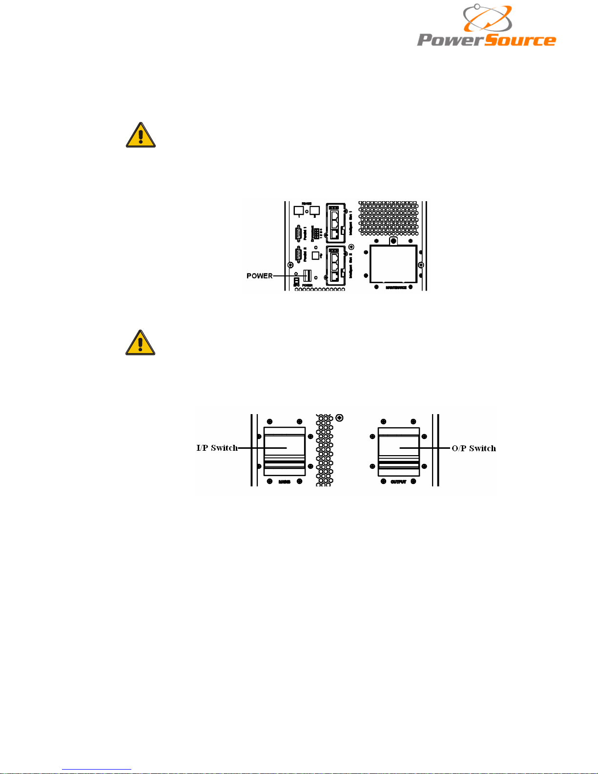
◆ Switch ON UPS input switch
If the Rectifier input is within voltage range, the rectifier will start up in 30 seconds then
the inverter will start up after then.
◆ Switch ON UPS output switch
If the recetifier fails at startup, the bypass LED will light up. When the inverter starts up,
the UPS will transfer from bypass mode to inverter mode, then the bypass LED
extinguishes and the inverter LED lights up.
No matter whether the UPS can work normally or not, all the status will be shown on the
LCD display.
Page 16

15
4.2.2 Test procedure
CAUTION!
The UPS is operating normally.It may take 60 seconds to boost up the
system and perform self-test completely.
◆ Switch off the MAINS to simulate utility failure, the rectifier will turn off and the battery
should feed the inverter without interruption. At this time, the LEDs of battery should be turned
on.
◆ Switch on the MAINS to simulate utility recovery, the rectifier will restart automatically
after 20 seconds and the inverter will supply to the load. It is suggested to use Dummy loads
for testing. The UPS can be loaded up to its maximum capacity during load test。
4.2.3 MAINTEN ANCE BYPASS
To supply the load via Mains, you may simply active the internal mechanical bypass switch.
CAUTION!
The load is not protected by the UPS when the internal mechanical
bypass system is active and the power is not conditioned.
Switch to mechanical bypass
CAUTION!
If the UPS is running normally and can be controlled through the display,
carry out steps 1 to 5; otherwise, jump to Step 4.
◆ Open the cover of maintenance switch, the UPS turns to bypass mode automatically.
◆ Turn on MAINTANCE breaker;
◆ Open BATTERY breaker;
◆ Switch OFF the MAINS breaker,
◆ Switch OFF OUTPUT breaker;
At this time the bypass source will supply to the load through the MAINTENANCE breaker.
Switch to normal operation (from mechanical bypass)
CAUTION!
Never attempt to switch the UPS back to normal operation until you
have verified that there are no internal UPS faults
Page 17
16
◆ Switch ON the outp ut breaker of the module.
◆ Switch ON the input breaker.
The UPS powers from the static bypass instead of the maintenance bypass, then
the bypass LED will light up.
◆ Switch OFF the maintenance bypass breaker, then the output is supplied by the
static bypass of the UPS.
◆ Put o n the maintenance switch cover.
The rectifier will operate normally after 30 seconds. If the inverter works normally,
the system will be transferred from bypass mode to normal mode.
4.2.4 Black(Cold) start pro cedure
CAUTION!
Follow these procedures when the input AC Utility Failure, but
battery is normal
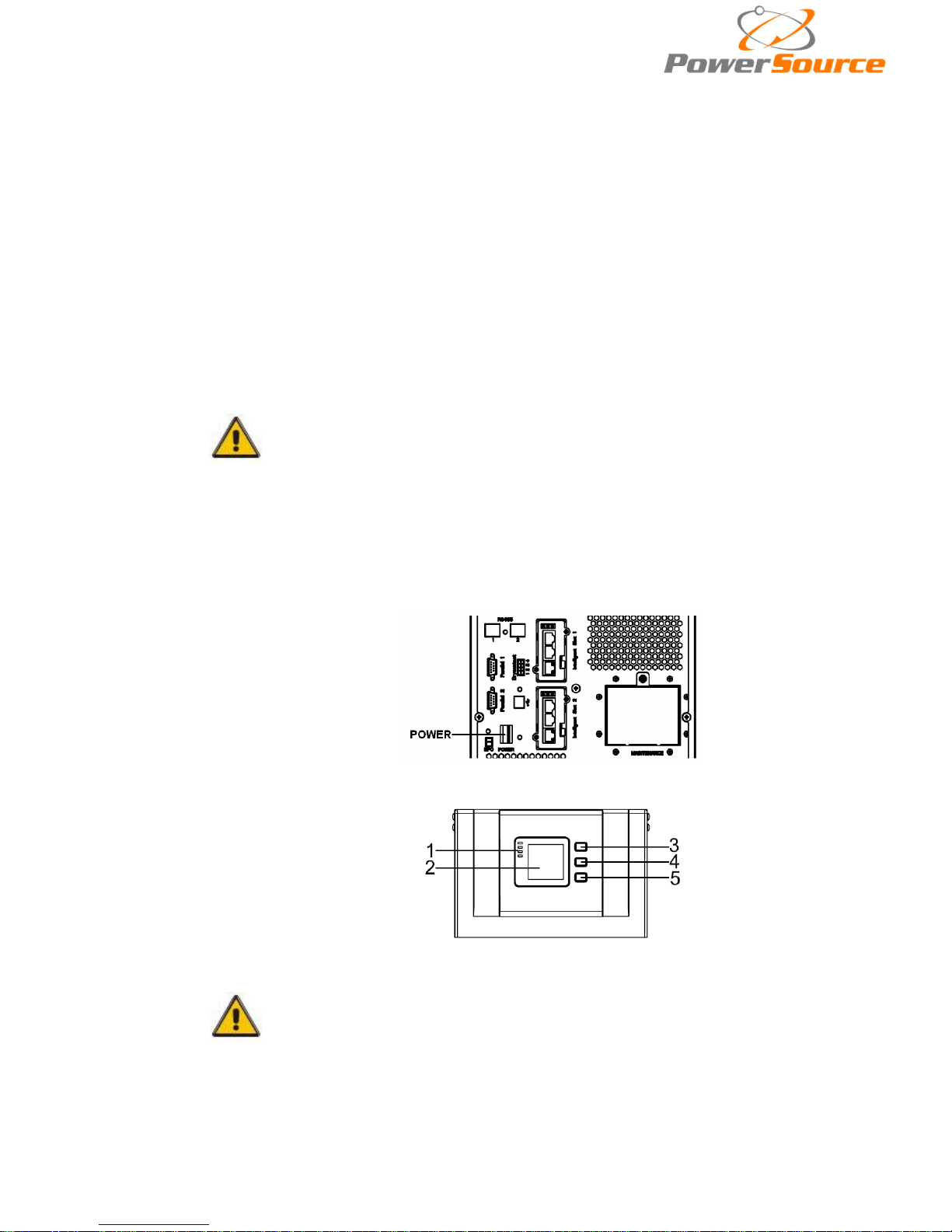
◆ Turn on the bat ter y switch.
The battery will feed the Auxiliary power board.
◆ Turn on the Output switch.
◆ Switch ON the power breaker (power will feed to auxiliar y pow er board).
◆ Trigger the cold start button as the posit ion 5 of the below drawing.
When battery normal, r ectifier starts operation, 30s later, inverter starts and
operates and batter y LED o n
CAUTION!
Please press the close start button after 30 seconds until closing
the battery switch.
Page 18
17
4.2.5 Shut down procedure
CAUTION!
This procedure should be followed to completely shut down the
UPS and the LOAD. After all power switches, isolators and circuit
breakers are opened, there will be no output.
◆ Open the BATTERY breaker;
◆ Open the UPS door to easily access to the main power switch;
◆ Switch OFF the input breaker.
◆ Open the OUTPUT power switch. The UPS shuts down;
◆ To completely isolate the UPS from AC Mains, all input switches of Utility shall
be completely off, which includes the ones for r ectifier and bypass.
◆ The primary input distribution panel, which is often located far away from the
UPS area, so a label should be posted to advise service personnel that the
UPS circuit is under maintenance。
WARNING!
Wait for about 5 minutes for the internal D.C. bus bar
capacitors to be completely discharged.
4.2.6 Parallel setting
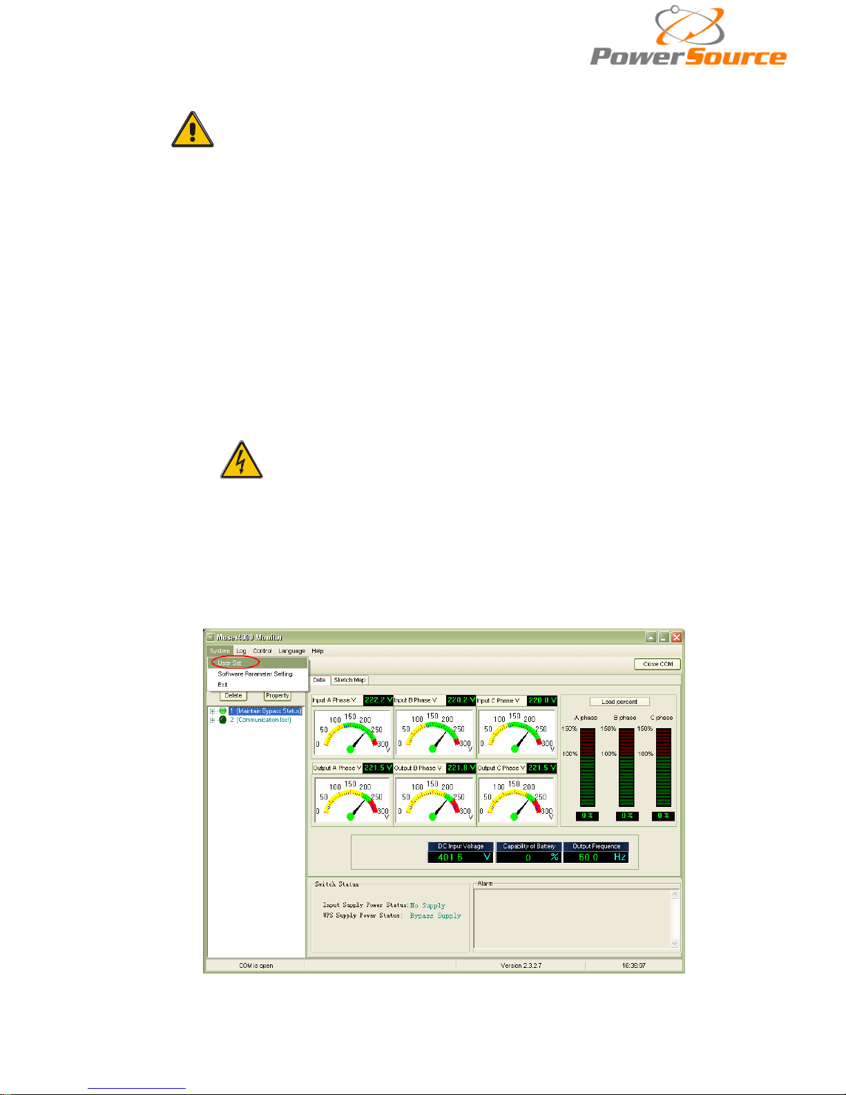
◆Connect the UPS with computer. Power on the U
PS.
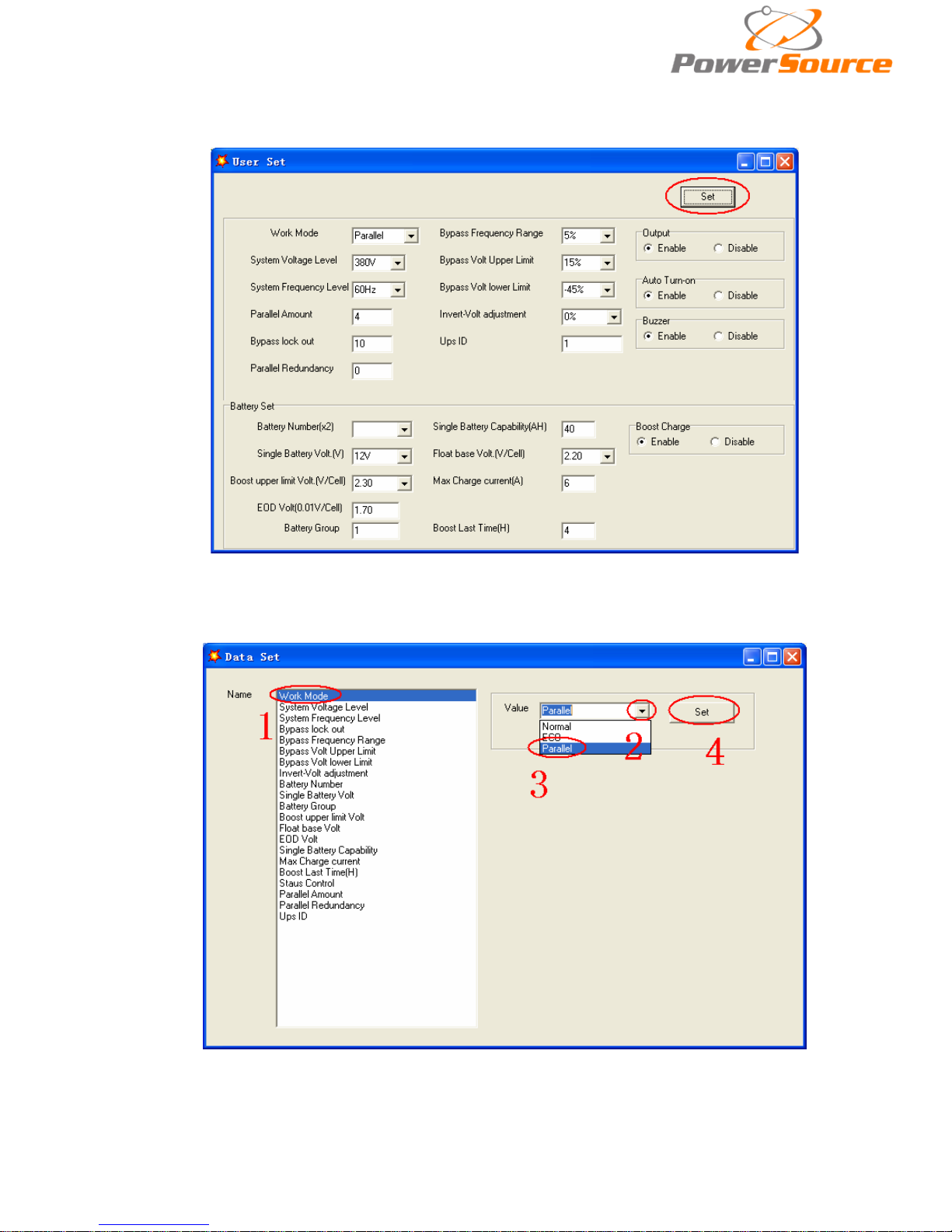
◆ Open Muser4000 software, after connecting with the UPS successfull y, click
“System”->“User Set”
Page 19
18
◆Click ‘Set” at “User Set” window;
◆At the window of “Data Set”, click “Work Mode”,, choose “Parallel” for the value, then click
“Set” as shown in bel ow picture. If the UPS sounds a “beep”, that means the setting is correct.
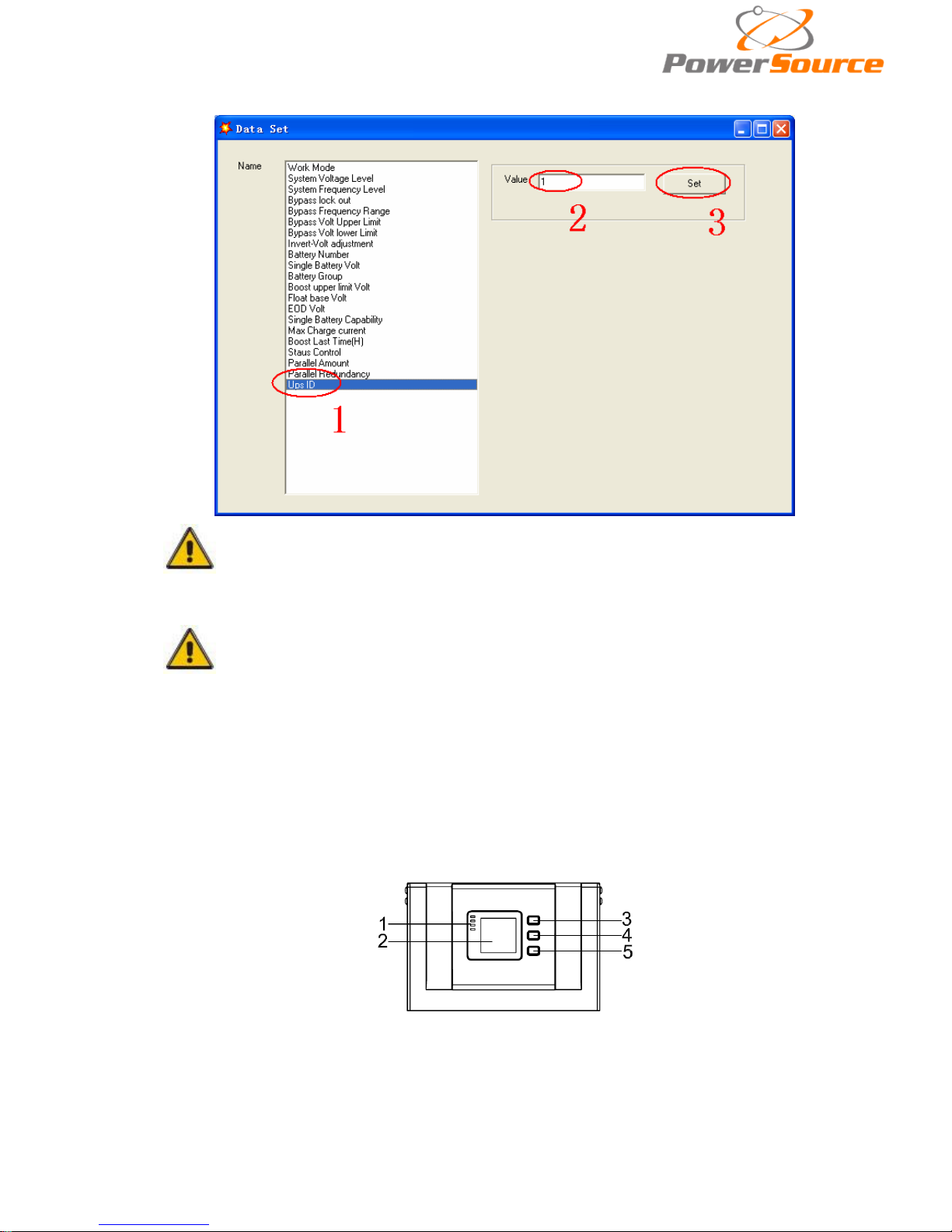
◆At the window of “Data Set”, click “Ups ID”, write a value for the parallel UPS ID at the right
side, such as “1”, then click “Set” as shown in below picture. If the UPS sounds a “beep”, that
Page 20
19
means the setting is correct.
CAUTION!
After changing the parallel system ID, the connection between
Muser4000 and equipment might be interrupted. If it occurs, please
re-connect in accordance with the instruction described before.
CAUTION!
Parallel cable cannot be connected when setting the parallel parameters.
◆After setting the UPSes needed to be paralleled, power off all the UPSes. Connect all the
UPSes accordi ng to “parallel cable installation”, and then power on the UPSes.
4.3 The LCD Display
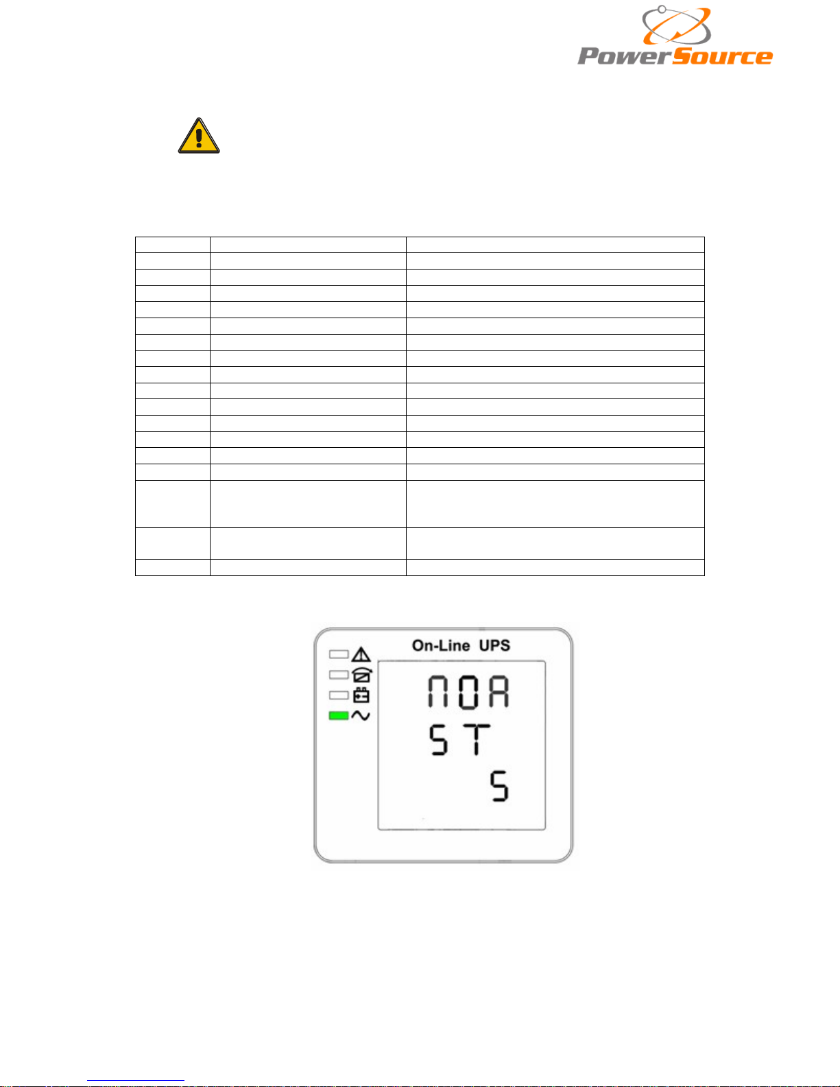
Overview of the operating panel of the UPS
(1)LED indicator (2)LCD display (3)Scroll button:enter to next item (4)Off button (5)On button
Page 21
20
Introduction
CAUTION!
The display provides more functions than those
described in this manual.
There are 17 interfaces available in the LCD display:
Item
Interface Description
Content Displayed
01
CODE
Operational status and mode
02
Input A(Input L1)
Voltage & Frequency
03
Inp ut B(Inp ut L2)
Voltage & Frequency
04
Inp ut C(Inp ut L3)
Voltage & Frequency
05
Bat. +
Voltage & Current
06
Bat. -
Voltage & Current
07
Backup time
Capa
city&T
ime
08
Output A(Output L1)
Voltage&Frequency
09
Output B(Output L2)
Voltage&Frequency
10
Output C(Output L3)
Voltage&Frequency
11
Load A
Load
12
Load B
Load
13
Load C
Load
14
Total Load
Load
15
Temperature
battery temperature(need to connect ba
tter
sensor,Internal temperature and ambient
temperature
16
Software version & model
Version of rectifier software, version of invert er
software, model
17
CODE
Alarm Code(Warming Message)
1) When the UPS is connecting with the Utility or Battery at cold start mode, it shows as drawing
below:
Operational Status and mode(When t he UPS at single mode, it shows “NOR” or “ECO”, but If the
UPS at parallel mode, it shows “PAL” instead.)
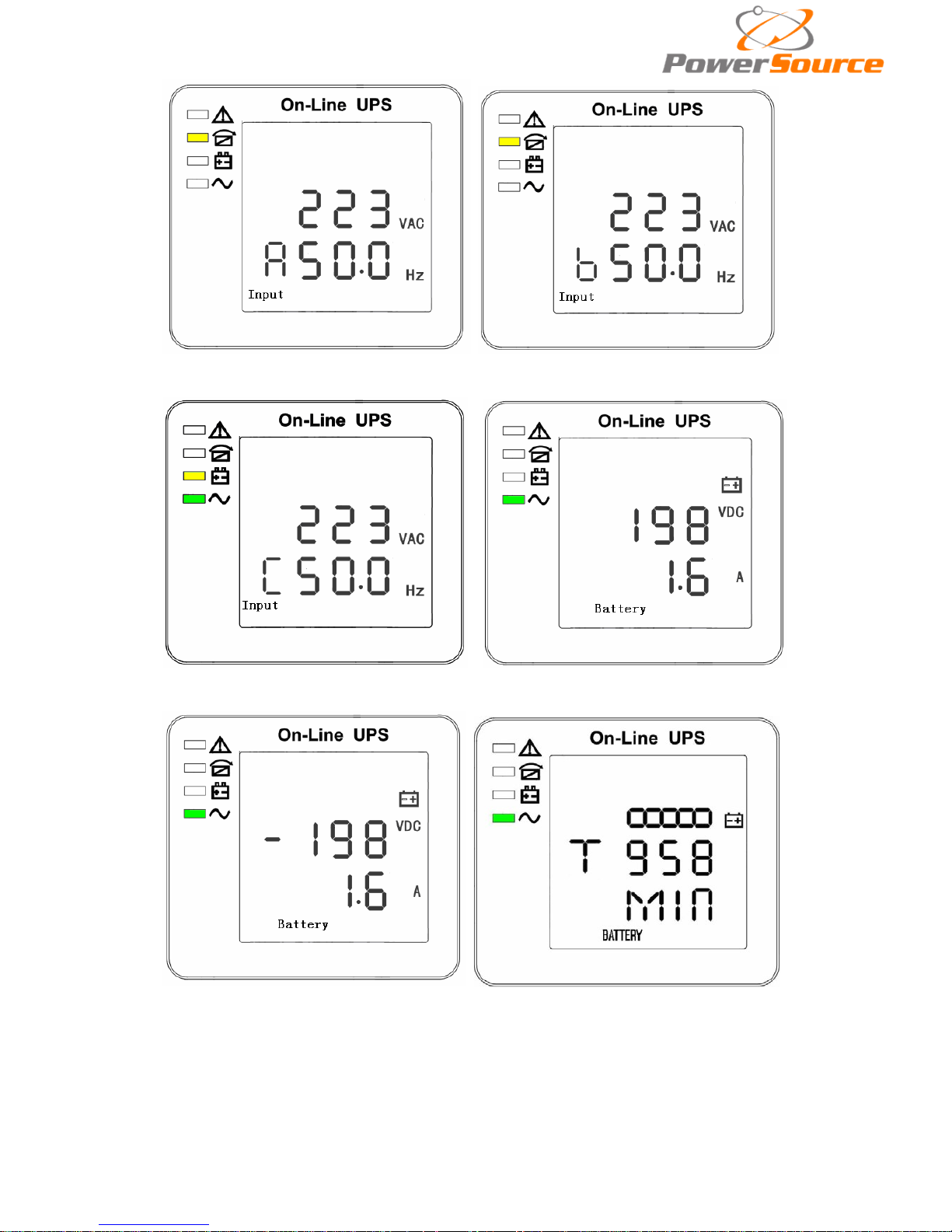
2) Press “scroll” button, the UPS goes to next page as shown below.
Page 22
21
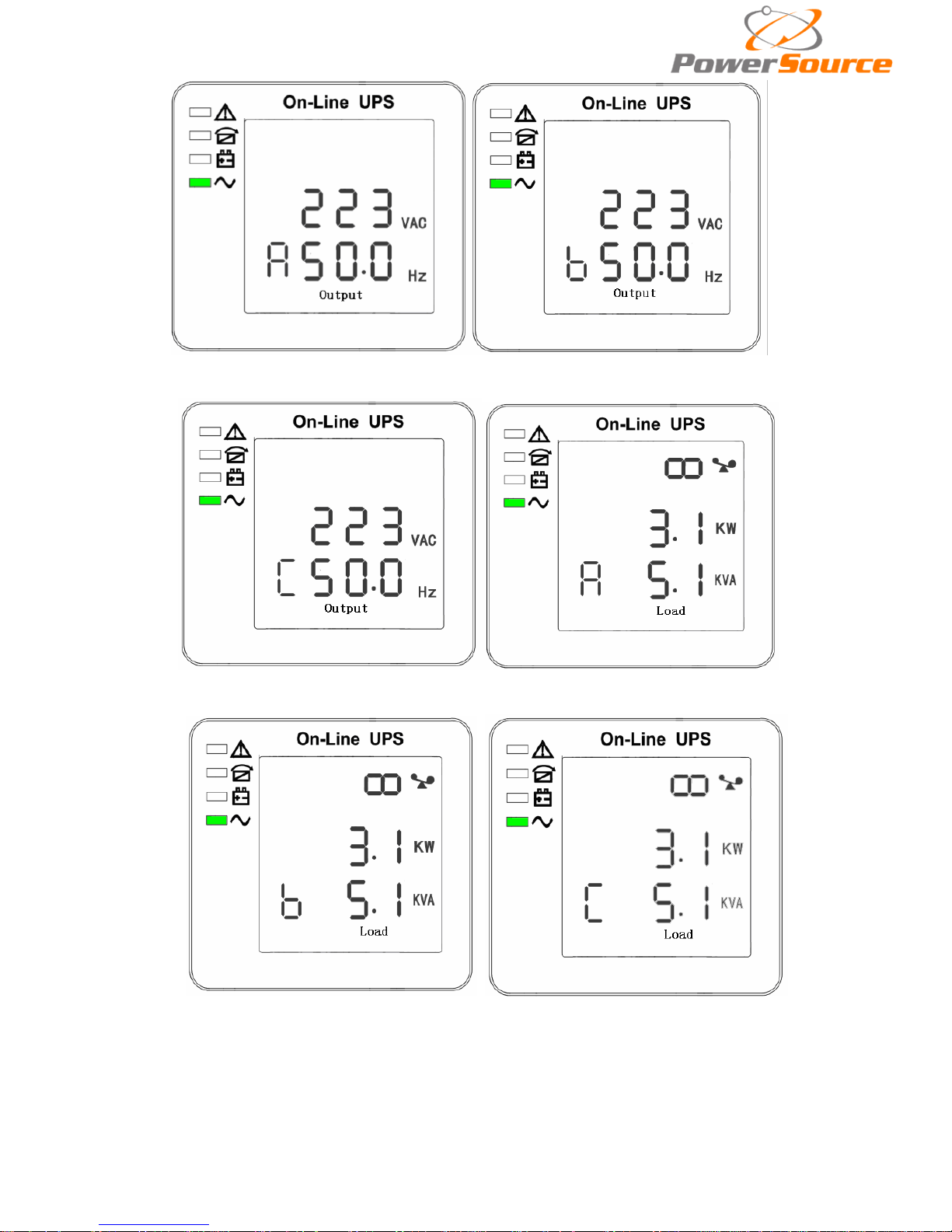
2.Phase A(L1) Input/Frequency 3. Phase B(L2) Input/Frequency
4. Phase C(L3) Input/Frequenc 5. Bat +(Positive)
6. Bat –(Negative) 7. Backup time
Page 23
22
8. Phase A(L1) Output Voltage/Frequency 9. Phase B(L2) Output Voltage/Frequency
10.Phase C(L3) Output Voltage/Frequency 11. Phase A(L1) Load Capacity
12. Phase B(L2) Load Capacity 13. Phase C(L3) Load Capacity
Page 24
23
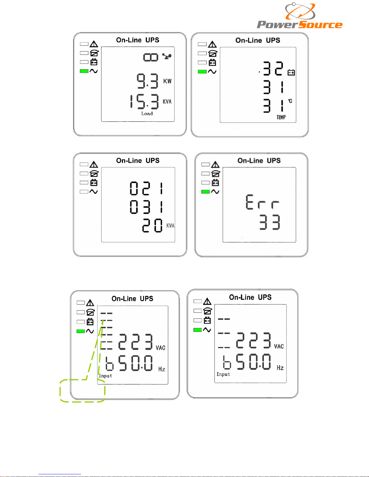
14.Total Load Capacity 15. Temperature(battery/Internal and am bient temperature)
16. Software version & model 17.Alarm Code
If has battery charging, above 2-13 interface windows will also display the charging status at
the same time as below:
Charging
Status
Boost Floating
3) Pressing “scroll” button, you may circulate all messages from the first one to the last one then
returns back to the first one and vice versa.
4) All alarm codes are present whe n abnor mal behavior(s) occur(s).
Page 25
24
4.4 Parameters
setting
The set ting fuction is controled by 3 buttons (Enter ,Off
▲, On ▼): Enter ---goes into the
setting page and value adjustment; Of f ▲ & On ▼---for choosing differ ent pages.
After the UPS turn ON, press buttons & ▲ for 2seconds and then goes into the setting
interface page.
Note: Figure at left corner is the page number of the setting pages.
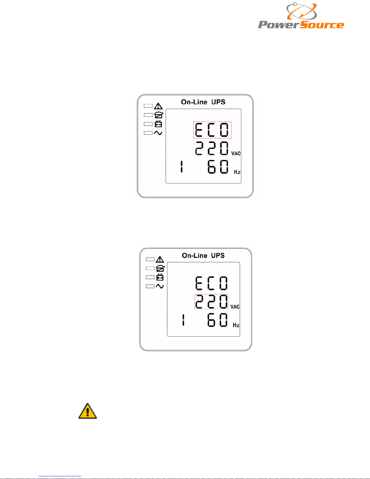
4.4.1 Mode sett ing
Mode settin g (Note : Inside the broken-line is the flashing part.)
After entering the setting menu, it’s mode setting defaulted, and the mode setting line flashing
as in above picture. ①use button Enter
to choose different mode. There are 3 different modes for
setting: ECO, PAL, NOR. ②press▲ or ▼ to exit the mode sett ing (save the mode setting), and goes
to output vo ltage setting or parallel redundancy quantity setting.
4.4.2 Output voltage setting
Output voltage setting (Note: Inside the broken-line is the flashing pa
rt.)
When under the mode setting press On▼ or when under frequency setting press Off▲, it
goes to the output voltage setting. The output voltage line flashes as in above picture. ①use button
Enter
to choose the different output voltage. There are 3 different voltages---220, 230, 240. ②
press▲ or ▼ to exit the output voltage setting (save the output voltage setting) and goes to mode
setting or frequenc y setting.
CAUTION!
When powered by inverter, it is necessary to turn off the inverter
before settin g voltage and freq uency level.
Page 26
25
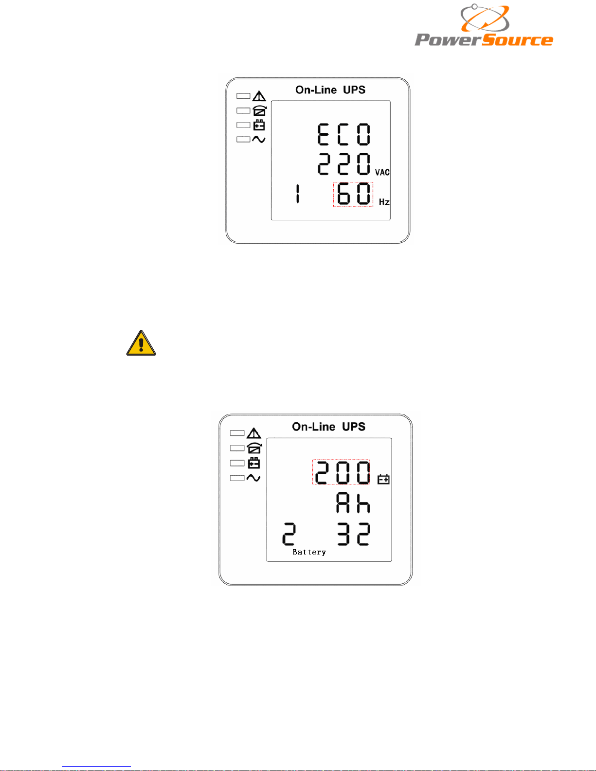
4.4.3 Frequency setting
Frequency setting (N ote: Inside the broken-line is the flashing part.)
When under the output voltage setting press On▼ or when under battery capacity setting press
Off▲, it goes to the frequency setting. The frequency line flashes as in above picture. ①use button
Enter
to choose the different frequency. There are 2 different frequency---50,60HZ. ②press▲ or ▼
to exit the frequency setting (save the frequency setting) and goes to output voltage setting or battery
capacity setting.
CAUTION!
When powered by inverter, it is necessary to turn off the inverter
before settin g voltage and freq uency level.
4.4.4 Battery capacity setting
Battery capacity setting (Note: Inside the broken-line is the flashing pa
rt.)
When under the frequency setting press On▼ or when under battery quantity setting press
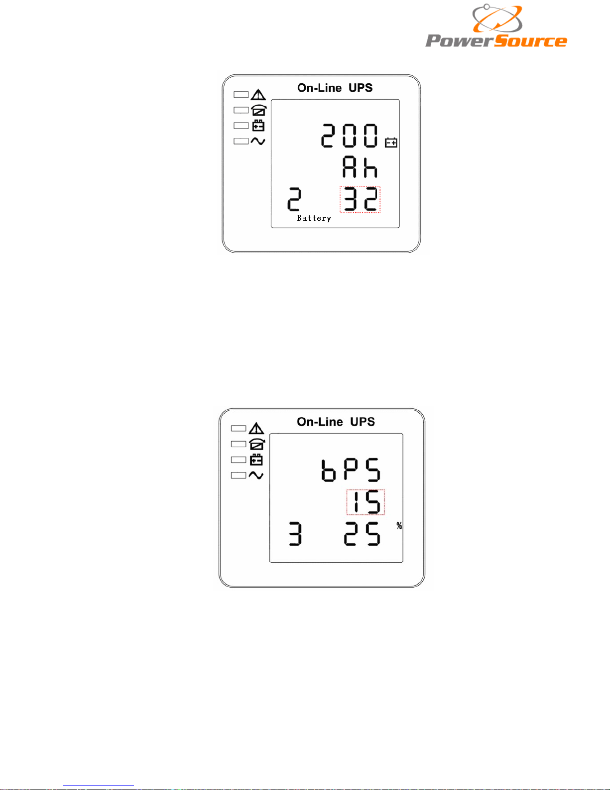
Off▲, it goes to the battery capacity setting. The battery capacity line flashes as in above picture. ①
use button Enter
t o choose the different battery capacity. Battery capacity range is 1-200Ah. (Note:
long-press of Enter
can adjustment battery capacity quickly.) ②press▲ or ▼ to exit the battery
capacity setting (save the capacity setting) and goes to frequency setting or battery quantity setting.
Page 27
26
4.4.5 Battery quantity setting
Battery quantity setting (Note: Inside the broken-line is the flashing pa
rt.)
When under the battery capacity setting press On▼ or when under bypass voltage upper limit
setting press Off▲, it goes to the battery quantity setting. The battery quantity line flashes as in above
picture. ①use button Enter
to choose the different battery quantity. Battery quantity range is
32,34,36,38,40. ②press▲ or ▼ to exit the battery quantity setting (save the battery quantity setting)
and goes to battery capacity setting or bypass voltage upper limit setting.
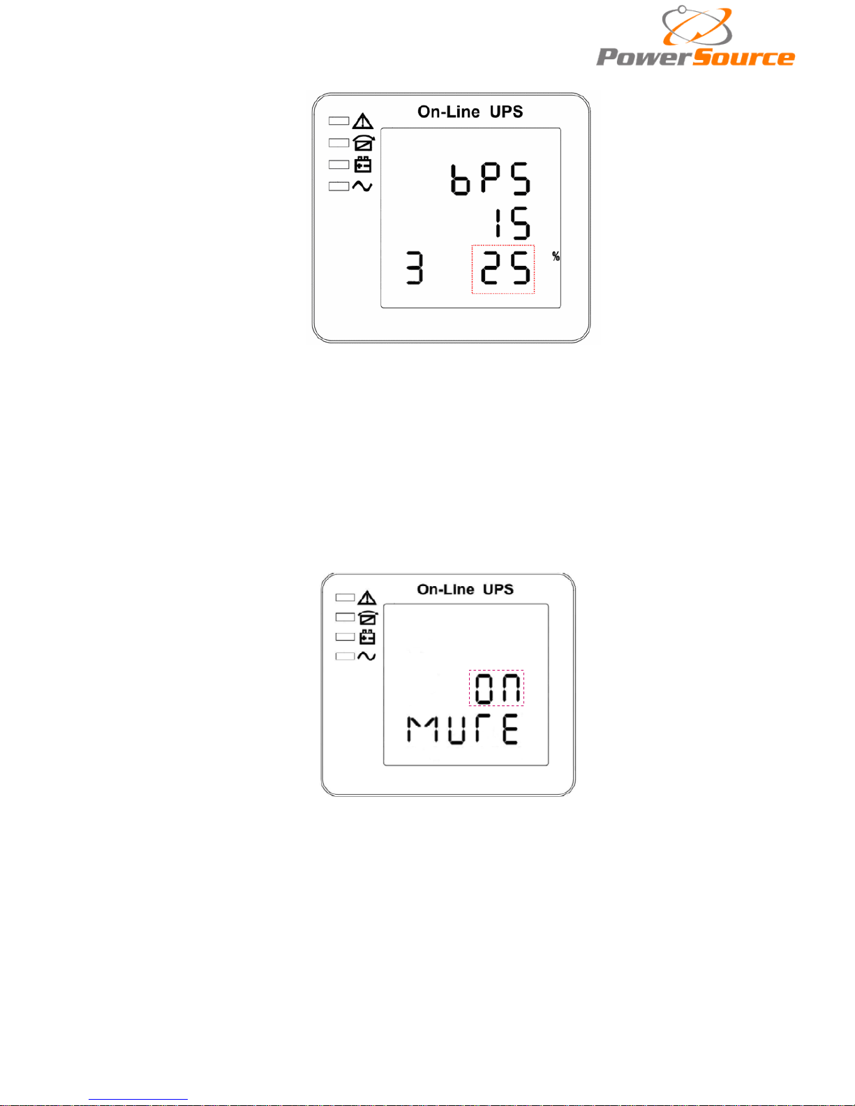
4.4.6 Bypass voltage upper limit setting
Bypass voltage up per limit setting (Note: Inside the broken-line is the flashing pa
rt.)
When under the battery quantity setting press On▼ or when under bypass voltage lower
setting press Off▲, it goes to the bypass upper limit setting. The bypass upper limit line flashes as in
above picture. ①use button Enter
to set the different bypass voltage upper limit. The bypass
voltage upper limit range is 5%,10%,15%,25%(25% only for 220V output). ②press▲ or ▼ to exit the
bypass voltage upper limit setting (save the bypass voltage upper limit setting) and goes t o battery
quantity se tting or bypass voltage lower limit setting.
Page 28
27
4.4.7 Bypass voltage lower limit setting
Bypass voltage lower limit setting (Note: Inside the broken-line is the flashing pa
rt.)
When under the bypass voltage upper limit setting press On▼ or when under parallel ID setting
press Off▲, it goes to the bypass lower limit setting. The bypass lower limit line flashes as in above
picture. (“-” for negative, positive does not have any symbol.) ①use button Enter
to set the different
bypass voltage lower limit. The bypass voltage lower limit range is 20%,30%,45%. ②press▲ or ▼ to
exit the bypass voltage lower limit setting (save the bypass voltage lower limit setting) and goes to
bypass upper limit setting or parallel ID setting.
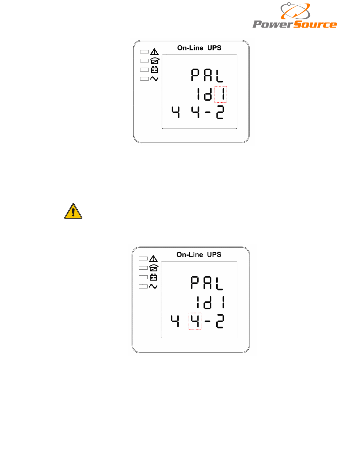
4.4.8 Buzzer Mute Setting
Buzzer Settings (note: red dashed box is the scintillation part
Press key ON under bypass volt-lo setting or press key OFF into buzzer setting under Parallel
operation ID setting. The scintillation of setting state shows as Figure 14 (Note: ON shows MUTE,
OFF shows NO MUTE).①press button Enter for Mute Cycle Settings, mute choice has On and Off.
②press button ON or OFF exits mute Setting (save mute setting state) and change to bypass volt-lo
setting or parallel operation ID Settings.
Page 29
28
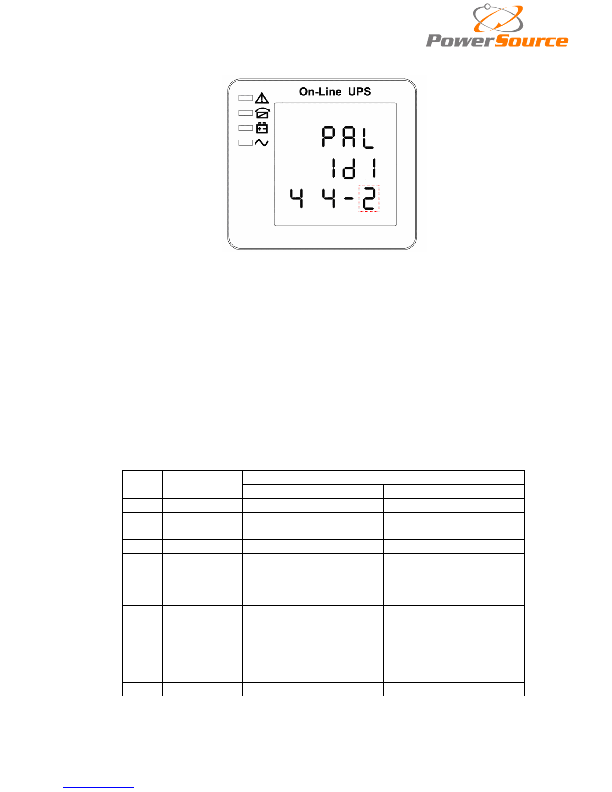
4.4.9 Parallel I D set t ing
Parallel ID setting (Note: Inside the broken-l ine is the flashing pa
rt.)
When under the bypass voltage lower limit setting press On▼ or when under parallel quantity
setting press Off▲, it goes to the parallel ID setting. The parallel ID flashes as in above picture. ①
use button Enter
to set the different parallel ID. The parallel ID range is 1~4. ②press▲ or ▼ to exit
the parallel ID setting (save the parallel ID setting) and goes to bypass lower limit setting or parallel
quantity se tting.
CAUTION!
Parallel cable cannot be connected when setting the parallel parameters.
4.4.10 Parallel quantity setting
Paralle l quantity setting (Note: Inside the broken-line is the flashi ng pa
rt.)
When under the parallel ID setting press On▼ or when under parallel redundancy quantity
setting press Off▲, it goes to the parallel quantity setting. The parallel quantity flashes as in above
picture. ①use button Enter
to set the parallel quantity. The parallel quantity range is 2~4. ②
press▲ or ▼ to exit the parallel quantity setting (save the parallel quantity setting) and goes to
parallel ID setting or parallel redundancy qu anti ty setting.
Page 30
29
4.4.11 Parallel redundan cy quantity setting
Paralle l redundancy quantity setting (Note: Inside the broken-line is the flashing pa
rt.)
When under the parallel quantity setting press On▼, it goes to the parallel redundancy quantity
setting. The parallel r e dundancy quantity flashes as in above picture. ①use but t on Enter
to set the
parallel redundancy quantity. The parallel redundancy quantity range is 0~3. ②press▲ to go to
parallel quantity setting, or ▼ to exit the mode setting. Then UPS LCD panel setting is accomplished.
4.5 Display Messages/Troubleshooting
This section lists the event and alarm messages that the UPS might display. The messages are
listed in alphabetical order. This section is listed with each alarm message to help you troubleshoot
problems .
Display messages
Operational Status and Mode(s)
Code
(ST)
Information
stand for
LED
Fault
Bypass
Battery
Inverter
1
Initialized
EXTINGUISH
EXTINGUISH
EXTINGUISH
EXTINGUISH
2
Standby Mode
EXTINGUISH
EXTINGUISH
X
EXTINGUISH
3
No Output
EXTINGUISH
EXTINGUISH
X
EXTINGUISH
4
Bypass Mode
EXTINGUISH
LIGHT
X
EXTINGUISH
5
Utilit y Mode
EXTINGUISH
EXTINGUISH
X
LIGHT
6
Battery Mode
EXTINGUISH
EXTINGUISH
LIGHT
EXTINGUISH
7
Battery
Self-diagnostics
EXTINGUISH EXTINGUISH
LIGHT
EXTINGUISH
8
Inverter is
starting up
EXTINGUISH
X
X
EXTINGUISH
9
ECO Mode
EXTINGUISH
X X X
10
EPO Mode
LIGHT
EXTINGUISH
X
EXTINGUISH
11
Maintenance
Bypass Mode
EXTINGUISH EXTINGUISH EXTINGUISH EXTINGUISH
12
Fault Mode
LIGHT
X X X
CAUTION:"X" means it is determine d by other conditions
Page 31

30
Alarm Information
Fault code
(Err)
UPS Alarm Warning
Buzzer
LED
1 Rectifier Fault Beep continuously Fault LED lit
2
Inverter fault(Including Inverter
bridge is shorted)
Beep continuously Fault LED lit
3
Inverter Thyristor short
Beep continuously
Fault LED lit
4
Inverter Thyristor br oken
Beep continuously
Fault LED lit
5
Bypass Thyristor short
Beep continuously
Fault LED lit
6
Bypass Thyristor broken
Beep continuously
Fault LED lit
7
Fuse broken
Beep continuously
Fault LED lit
8
Paralle l relay fault
Beep continuously
Fault LED lit
9
Fan fault
Beep continuously
Fault LED lit
10
Reserve
Beep continuously
Fault LED lit
11
Auxiliary power faul t
Beep continuously
Fault LED lit
12
Initializtion f ault
Beep continuously
Fault LED lit
13
P-Battery Charger fault
Beep continuously
Fault LED lit
14
N-Battery Charger fault
Beep continuously
Fault LED lit
15
DC Bus over voltage
Beep continuously
Fault LED lit
16
DC Bus below voltage
Beep continuously
Fault LED lit
17
DC bus unbalance
Beep continuously
Fault LED lit
18
Soft start failed
Beep continuously
Fault LED lit
19
Rectifier Over Temperature
Twice per second
Fault LED lit
20
Inverter Over temperature
Twice per second
Fault LED lit
21
Reserve
Twice per second
Fault LED lit
22
Battery reverse
Twice per second
Fault LED lit
23
Cable connection error
Twice per second
Fault LED lit
24
CAN comm. Fault
Twice per second
Fault LED lit
25
Parallel load shar ing fault
Twice per second
Fault LED lit
26
Battery over voltage
Once per second
Fault LED blinking
27
Mains Si te Wiring Fault
Once per second
Fault LED blinking
28
Bypass Site Wiring Fault
Once per second
Fault LED blinking
29
Output Short-circuit
Once per second
Fault LED blinking
30
Rectifier over current
Once per second
Fault LED blinking
31
Bypass over curre nt
Once per second
BPS LED b link ing
32
Overload
Once per second
INV or BPS LED
blinking
33
No battery
Once per second
Battery LED blinking
34
Battery under voltage
Once per second
Battery LED blinking
35
Battery low pre-warning
Once per second
Battery LED blinking
36
Internal Communication Error
Once per 2 seconds
Fault LED blinking
37
DC component over limit.
Once per 2 seconds
INV LED blinking
38
Paralle l Overload
Once per 2 seconds
INV LED blinking
39
Mains volt. Abnormal
Once per 2 seconds
Battery LED lit
40
Mains freq. abnormal
Once per 2 seconds
Battery LED lit
41
Bypass Not Available
BPS LED blinking
42
Bypass unable to trace
BPS LED blinking
43
Inverter on invalid
44
Reserve
45
inverter not on
Page 32
31
4.6 Options
SNMP card: internal SNMP / external SNMP optional
◆ Loosen the 2 torque screws ( on each side of the card).
◆ Carefully pull out the card. Reverse the proc edure f or re-installation
The slot called SNMP supports the MEGAtec protocol. We advise that NetAgent II-3 port is
also a tool to remotely monitor and manage any UPS system
NetAgent II-3Ports supports the Modem Dial-in(PPP) function to enable the remote control
via the internet when the network is unavailable .
In addition to the features of a standard NetAgent Mini, NetAgent II has the option to add
NetFeeler Lite to detect temperature, humidity, smoke and security sensors. Thus, making
NetAgent II a versatile management tool. NetAgent II also supports multiple languages and is
setup for web-based auto language detection .
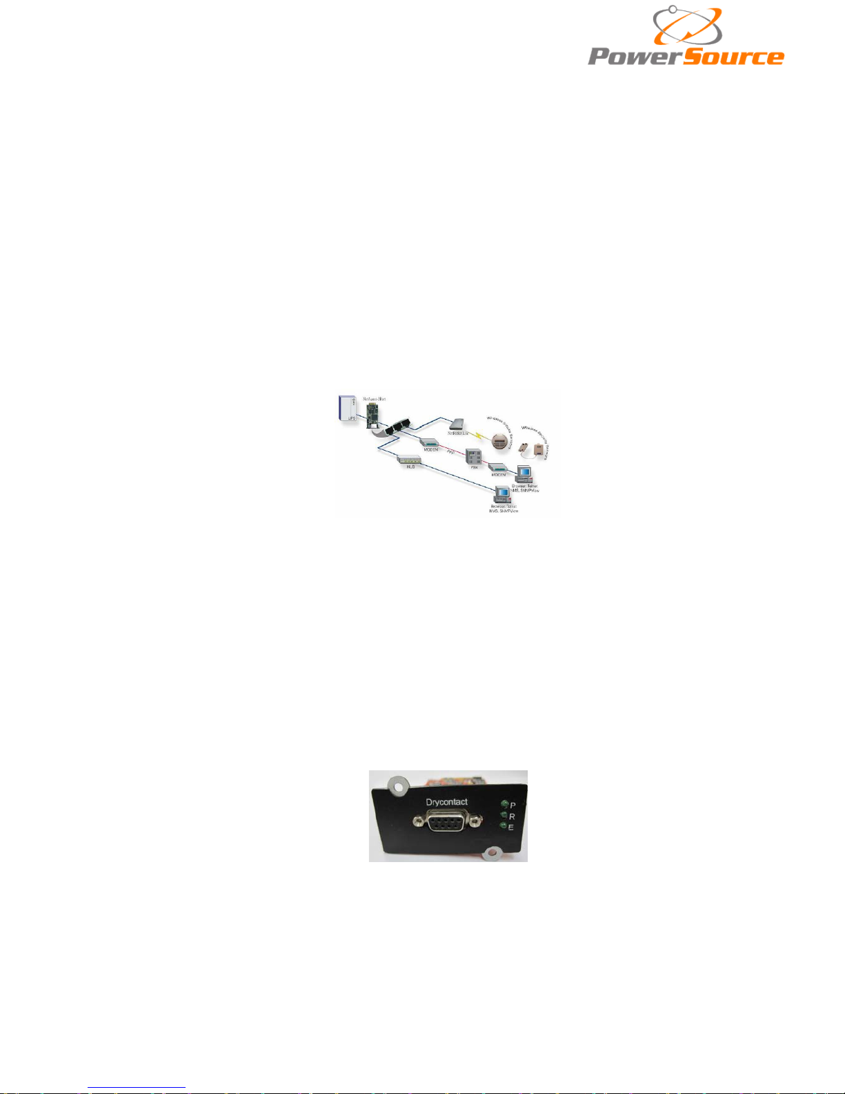
Typical topology of the UPS Network Management
Relay card
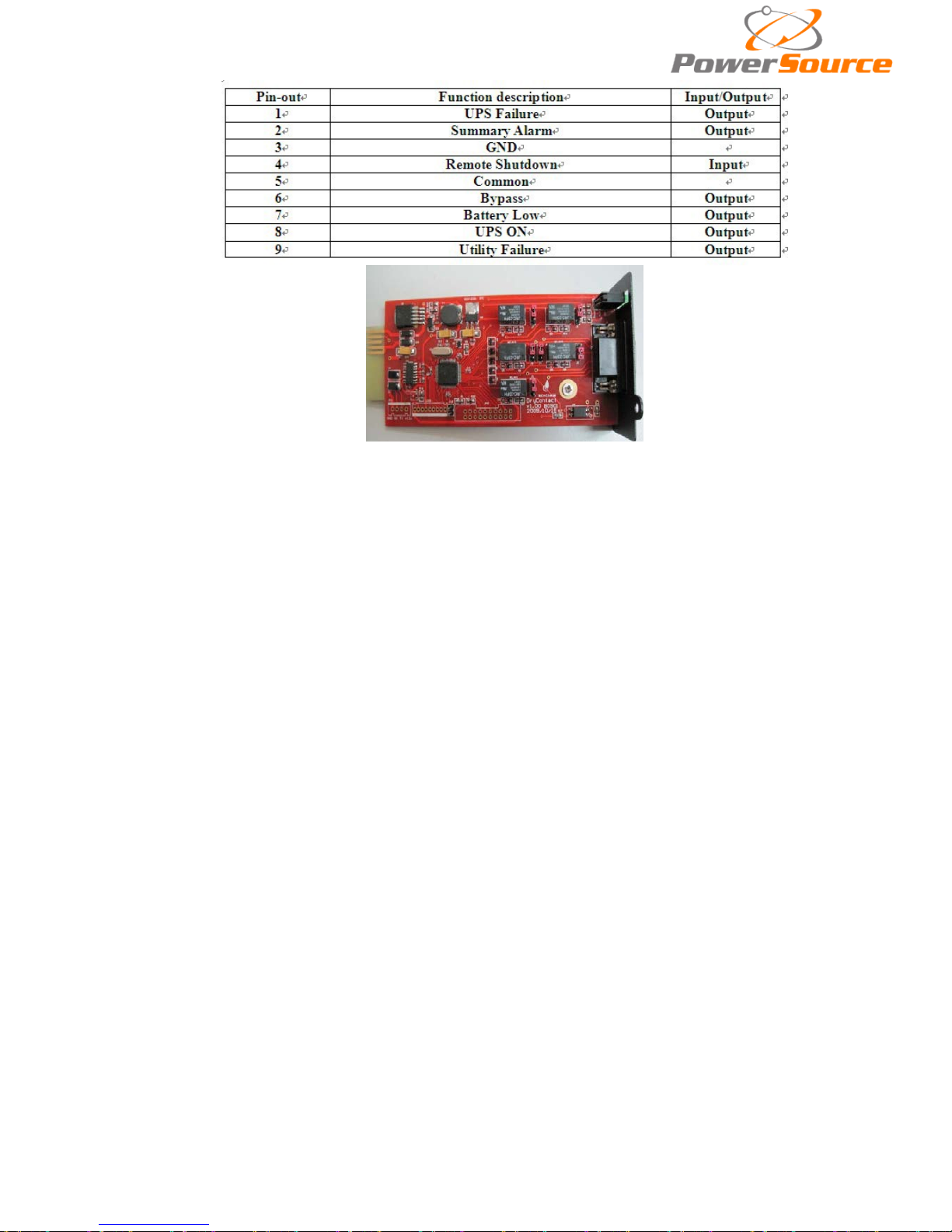
The card is used for providing the interface for UPS peripheral monitoring. The contact
signals can reflect UPS running status. The card is connected to peripheral monitoring devices
via DB9 female to facilitate the effective monitoring of the real-time status of UPS and timely
feedback the status to monitor when abnormal situation occurs (such as UJPS failure, mains
interruption, UPS bypass and ect.). It is installed in the intelligent slot of the UPS.
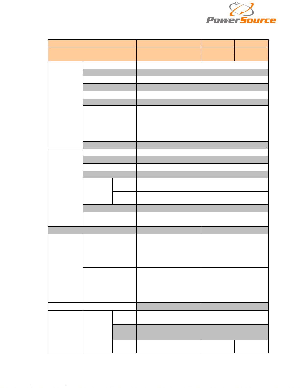
The relay card includes 6 output ports and one input port. Please refer to the following table
for detail.
DB9 interface: Connect to upper control terminal. The definition of the pins is defined as
below:
Page 33
32
Page 34
33
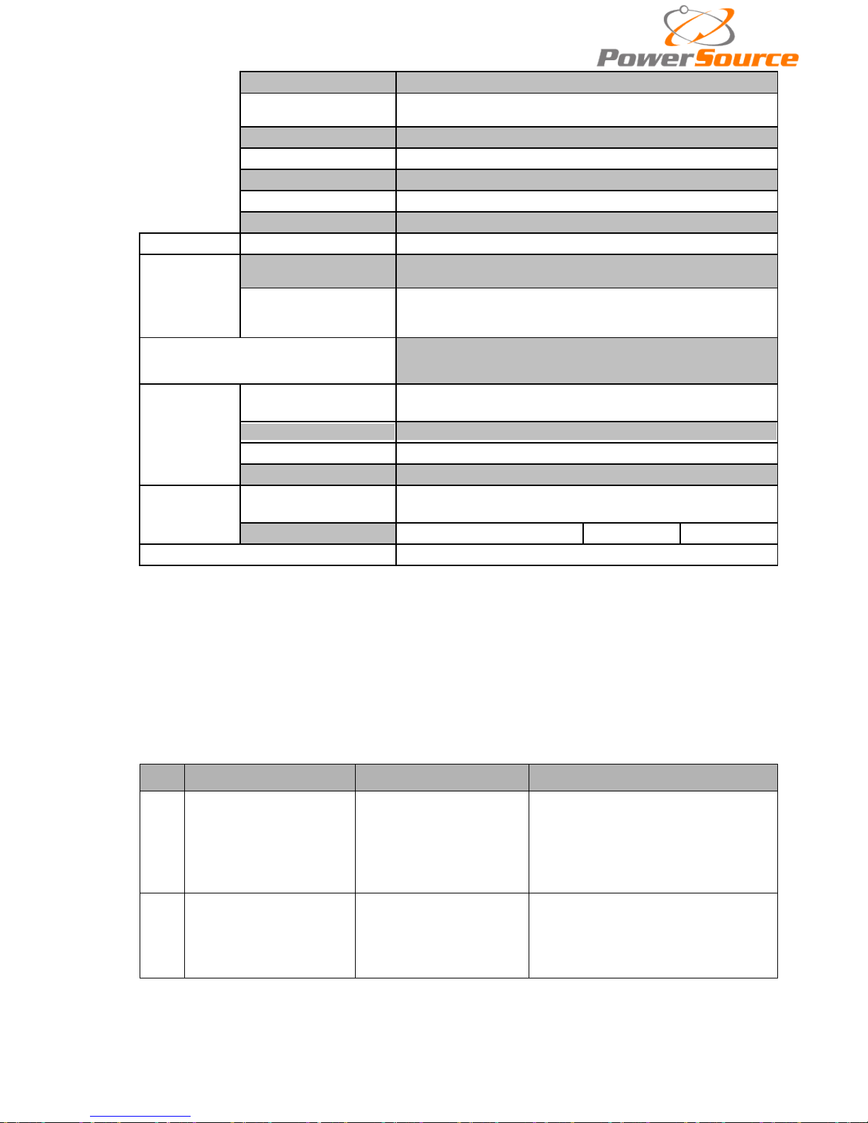
Appendix 1 Specifications
Model
10KVA(S/H)
15KVA(S/H)
20KVA(S/H)
Capacity
10KVA
15KVA
20KVA
9KW
13.5KW
18KW
Input
Phase
3 Phase 4 Wires and Ground
Rated Voltage
380/400/415Vac
Voltage Range
208~478Vac
Frequency Range
45-55Hz at 50Hz/54-66Hz at 60Hz (auto sensing)
Power Factor
≥0.99
Current THDi
≤3%(100% nonlinear load)
Bypass Voltage
Range
Max.voltage: 220Vac: +25%(optional +5%,+10%,+15% )
230Vac: +20%(optional +10%,+15% )
240Vac: +15%(optional +10% )
Min. voltage: -45% ( optional -20%、-30%)
Frequency protection range: ±10%
Generator Input
Support
Output
Phase
3 Phase 4 Wires and Ground
Rated Voltage
380/400/415Vac
Power Factor
0.9
Voltage Regulation
±1%
Frequency
Utility
Mode
±1%、±2%、±4%、±5%、±10% of the rated
frequency(optional)
Battery
Mode
(50/60±0.2%)Hz
Crest Factor
3:1
THD
≤2% with linear load
≤5% with non linear load
Efficiency
≥93.5% at normal mode
≥94.5% at normal mode
Battery
Voltage
Standard unit: ±120Vdc
(20pcs 12V9AH);
Long run unit :
±96V/±108V/±120Vdc
(16/18/20pcs opt ional)
Standard unit: ±120Vdc
(2x20pcs 12V9AH);
Long run unit Optional
Voltage:
±96V/±108V/±120Vdc
(16/18/20pcs opt ional)
Charg e C urrent(A)
(charge current can be
set according
to
battery capacit y
installed)
Standard unit: 1.35A
Long run unit: Max.current
10A
Standard unit: 2.7A Long
run unit: Max.current
10A
Transfer Time
Utilit y to Battery : 0ms; Utility to bypass: 0ms
Protection
Overload
AC
Mode
Load≤110%: last 60min,≤125%: last 10min
,
≤150%: last
1min,≥150% change to bypass immediately。
Bat.
Mode
Load≤110%: last 10min,≤125%: last 1min,≤150%: last 5S
,
≥150% shut down UPS immediately。
Bypass
Mode
Breaker 20A
Breaker 32A Breaker 40A
Page 35
34
Short Circui t
Hold Whole
System
Overheat
Line Mode: Switch to Bypass ; Backup Mode: Shut down
UPS immediately
Battery Low
Alarm and Switch off
Self-diagnostics
Upon Power On and Software Control
EPO(optional)
Shut down UPS immediately
Battery Advanced Battery Management
Noise Suppression
Complies with EN62040-2
Alarms
Audible & Visual
Line Failure, Battery Low, Overload, System Fault
Display
Status LED & LCD
Line Mode, Bypass Mode, Battery Low, Battery Bad,
Overload & UPS Fault
Reading O n the LCD
Inp ut Voltage, Input Frequency, Output Voltage,
Output
Frequency, Load Percentage, Battery Voltage & Inner
Temperature
Comunication Interface
USB, RS485, Parallel (optional), Coupler dry contact,
Intelligent slot, SNMP card (optional), Rela y card (optional)
Environment
Operating
Temperature
0℃~40℃
Storage Temperature
-25℃~55
℃
Humidity
0~95% non condensing
Altitude
< 1500m.When>1500m,lower the rated power for use
Other
Unit
Dimensions(D×W×H )
828x250x868
Weight (Kg)
95/42 146/44 147/45
Safety Conformance
CE,EN/IEC 62040-2,EN/IEC 62040-1-1
Appendix 2 Problems and Solution
In case the UPS can not work normally, it m ight be wrong in install ation, wiring or operation.
Please check these aspects first. If all these aspects are checked without any problem, please
consult with local agent right away and provide below informat ions.
(1) Product model name and serial number.
(2) Try to describe the fault with more details, such as LCD display info, LED lights status,
etc.
Read the user manual carefully, it can help a lot for usi ng this UPS in the right way. Some FAQ
(frequently asked questions) may help you to troubleshoot your problem easily.
No. Problem Possible reaso n
Solution
1
Utility is co
nnected but
the UPS can not
be
powered ON.
Input power supply is
not connected;
Input voltage low;
The input swith of th
e
module is not switche
d
on .
measure if the UPS
input
voltage/frequency are within th
e
window.
Check if all modules input
are
switched on
2
Utility normal but
Utiltiy
LED does not light on
,
and the UPS
operates
at battery mode
The input breakers of
the Modules are not
switched on;
input cable is not well
connected
Switch on the input breaker;
Make sure the input cable is well
connected.
Page 36

35
3
The UPS does no
t
indicate any failure,
but
output do not
have
voltage
Output cable does not
well connected;
Output breaker do not
switch on
Make sure the output cable is well
connected;
Switch on the output breaker.
4
Utility LED is flashing
Utility voltage exceeds
UPS input range.
If the UPS operates at
battery
mode, please pay attention to
the
remaining backup time needed
for
your system.
5
Battery LED is flashing
but
no charge voltage and
current
Battery breaker does not
switch on, or batteries
are damaged, or battery
is reversely connected.
battery number and
capacity
are not set
correctly.
Switch on the battery breaker. If
batteries are damaged, need
to
replace whole group
batteries,
Connect the battery cables
correctly;
Go to LCD setting of the
battery
number and capacity, set the
correct data.
6
Buzzer beeps every 0.5
seconds and
LCD
display “output
overload”
Overload
remove some load
7
Buzzer long beep
s,
LCD
display “29”fault
code
The UPS output is in
short circuit
Make sure the load is not in short
circuit, then restart the UPS.
8
The UPS only works on
bypass mode
The UPS is set to ECO
mode, or the
transfer
times to bypass mo
de
are limited.
Set the UPS working mode to
Single Module type(non-p
arallel) or
to reset the times of tra
nsferring to
bypass or re-start the UPS
9
Can not Black start
Battery switch is not
properly closed;
Battery fuse is no
t
open;
Or Battery low;
Battery q
uantity set
wrong;
Power breaker in th
e
rear panel not
switch
ON.
Close the battery switch;
Change the fuse;
Recharge the battery;
Power ON the UPS with AC to set
the battery quantity
&quantity;
Switch
on the power breaker.
10
Buzzer beeps
continuously and LCD
indicates 1,3,5,9,15, etc
fault codes
UPS is out of order
Consult with your local agent for
repair
Page 37
36
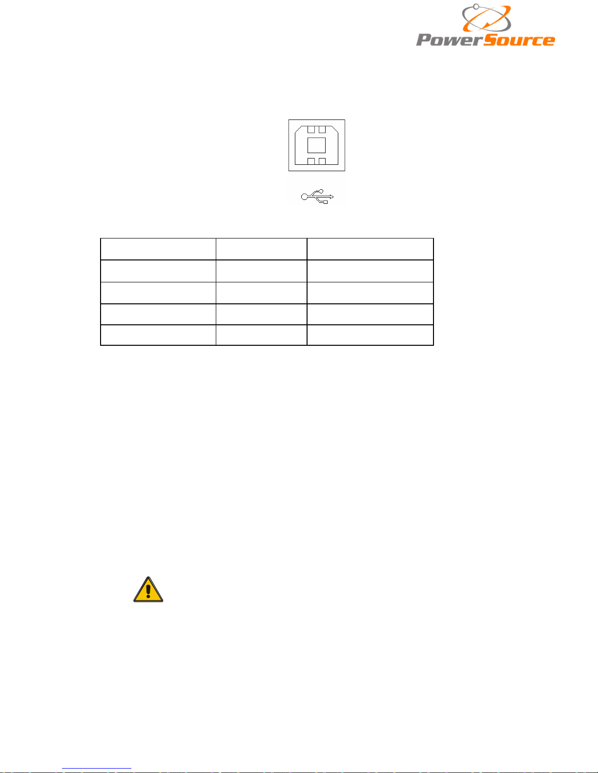
Appendix 3 USB communication port definition
Definition of port:
Connection between PC USB port and UPS USB port.
PC USB port
UPS USB port
Description
Pin 1
Pin 1
PC : +5V
Pin 2
Pin 2
PC : DPLUS signal
Pin 3
Pin 3
PC :DMINUS signal
Pin 4
Pin 4
Signal ground
Available function of USB
◆ Monitor UPS power status。
◆ Monitor UPS alarm info。
◆ Monitor UPS running parameters。
◆ Timing off/on setting。
Communication data format
Baud rate ---------- 9600bps
Byte length ---------- 8bit
End bit ---------- 1bit
Parity check ---------non
CAUTION!
USB & RS485 ports cannot be used at the same time.
Page 38
37
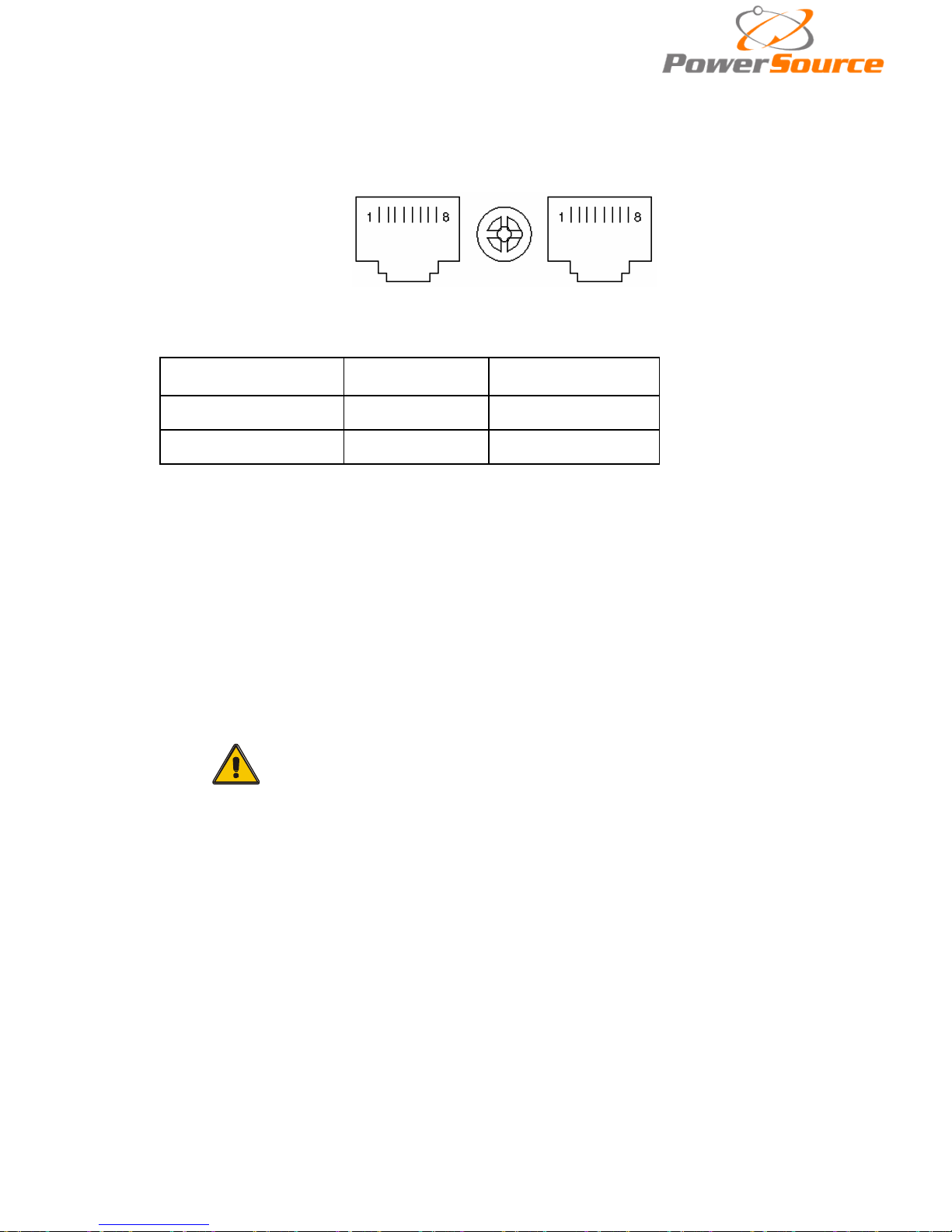
Appendix 4 RS485 communication port definition
Definition of port:
Connection between the Device’s RS485 port and UPS R S485 port.
device(RJ45) UPS(RJ45)
Description
Pin 1/5
Pin 1/5
485+ “A“
Pin 2/4
Pin 2/4
485 -“B”
Available function of RS485
◆ Monitor UPS power status。
◆ Monitor UPS alarm info。
◆ Monitor UPS running parameters。
◆ Timing off/on setting。
CAUTION!
USB & RS485 ports cannot be used at the same time.
Page 39
38
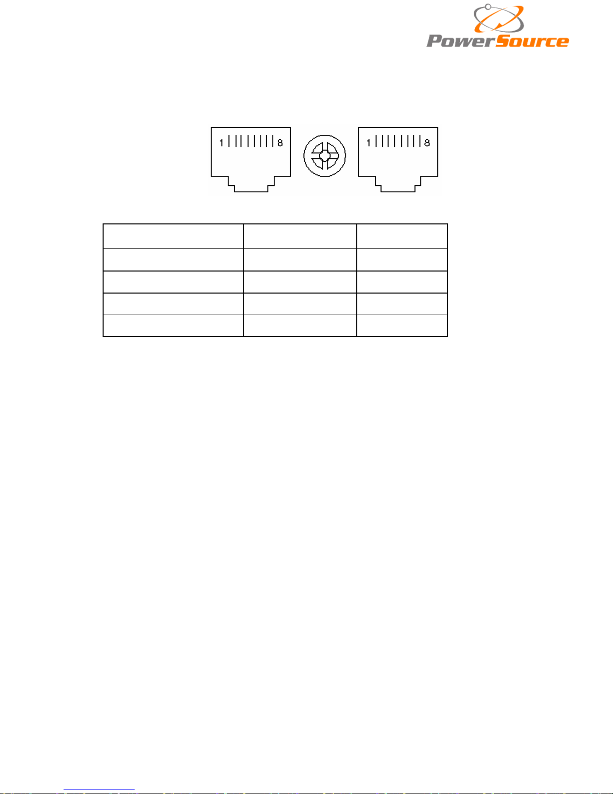
Appendix 5 BAT_T communication port definition
Definition of port:
Temperature sentor’s RS485 port and UPS’s RS485 port.
Temperature sentor(RJ45) UPS2 BAT_T(RJ45)
Description
Pin 1/5
Pin 1/5
TX
Pin 2/4
Pin 2/4
RX
Pin 7
Pin 7
12V
Pin 8
Pin 8
GND
Available function of BAT_T
◆Battery environment temperature monitoring.
◆Charging voltage modulation depending on batteries’ temperature
.
Page 40
39
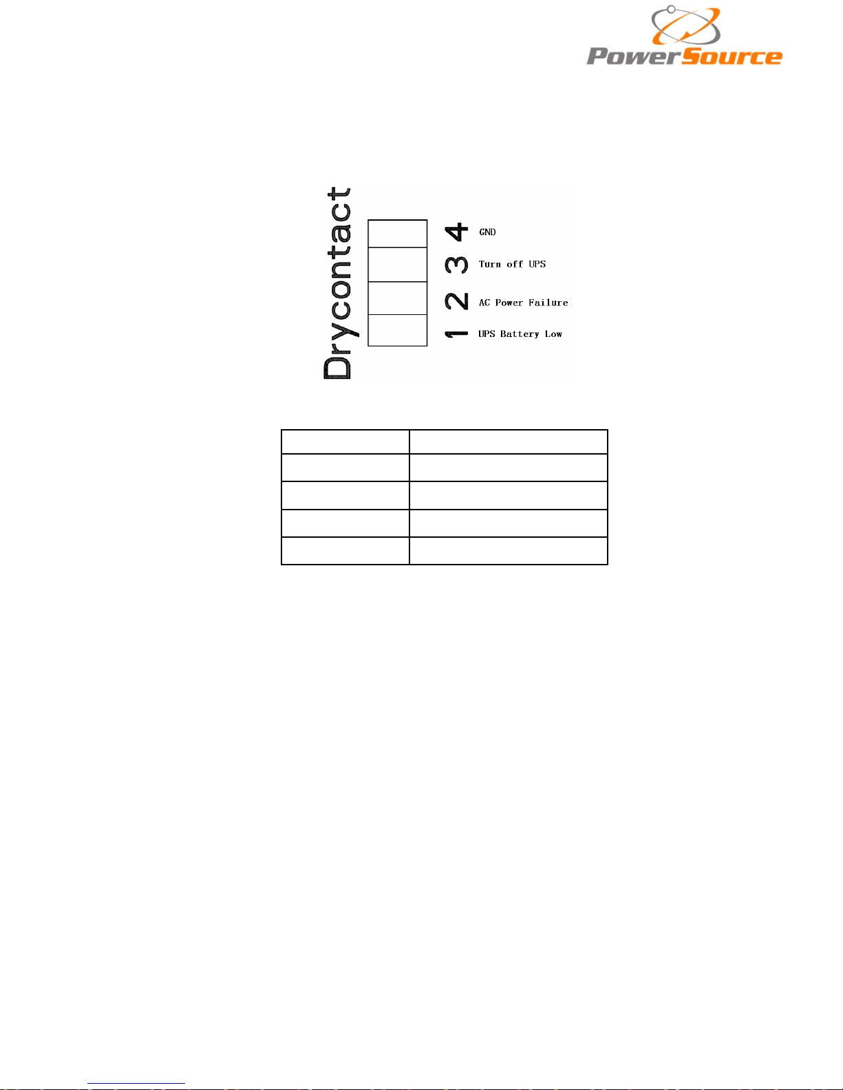
Appendix 6 Drycontact port communication port
definition
Definition of Male port:
Instruction:
UPS(DB9)
Instruction
Pin1 UPS Battery Low
Pin2 AC Power Failure
Pin3 Turn o ff UPS
Pin4 Common GND
Function descript ion:
◆ Monitor UPS status;
◆ Monitor UPS battery status;
◆ Shutdown UPS.
Page 41
40
Appendix 7 REPO instruction
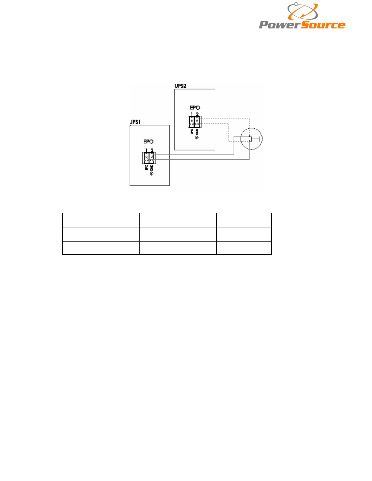
Definition of port:
Connection diagram:
Connection between the butt on and UPS REPO port.
Button
UPS REPO
Description
Pin 1
Pin 1
EPO
Pin 2
Pin 2
GND
◆A remote emer gency stop switch (Dr y contact signal and “normally open” - not provided) c an be
installed in a remote location and connec tion through simple wires to the REPO connector.
◆The remote switch can be connected to several UPS’s in a parallel architecture allowing the user to
stops all units at once.
 Loading...