

PowerSonic PS-4100, PS-260, PS-605, PS-445, PS-610 Technical Handbook
...
TECHNICAL HANDBOOK
SEALED LEAD-ACID BATTERIES
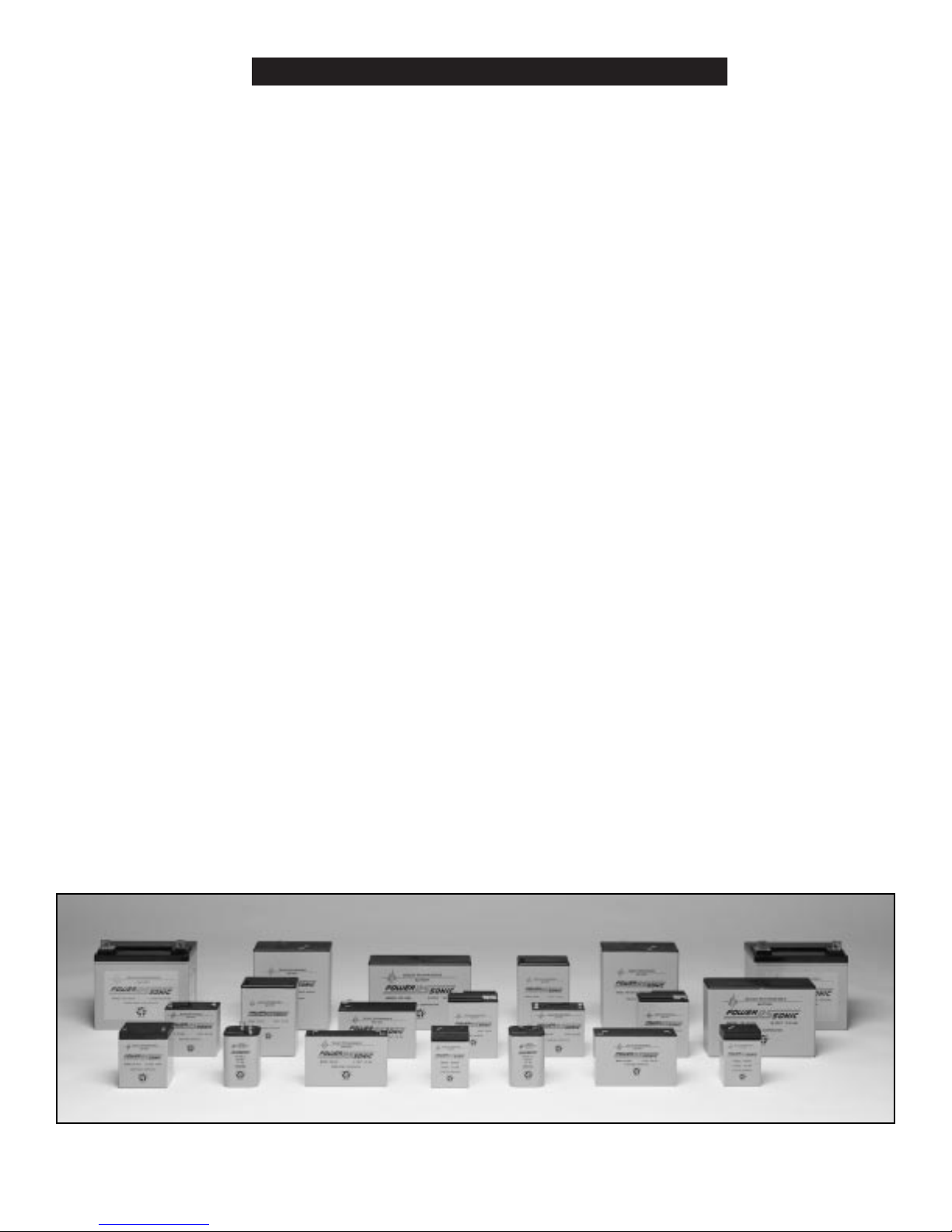
Sealed/Maintenance-Free
The valve regulated, spill-proof construction of the
Power-Sonic battery allows trouble-free, safe operation
in any position. There is no need to add electrolyte, as
gases generated during over-charge are recombined in a
unique “oxygen cycle.”
Long Shelf Life
A low self-discharge rate permits storage of fully charged
batteries for up to a year at room temperature before
charging is required. Lower storage temperatures enhance
shelf life characteristics even further.
Design Flexibility
Batteries may be used in series and/or parallel to obtain
choice of voltage and capacity. Due to recent design
breakthroughs, the same battery may be used in either
cyclic or standby applications. Over 50 models are available to choose from.
Deep Discharge Recovery
Special separators, advanced plate composition, and a
carefully balanced electrolyte system have greatly
improved the ability of recovering from excessively deep
discharge.
Economical
The high watt-hour per dollar value is made possible by
the materials used in a sealed lead-acid battery: they are
readily available and low in cost.
Easy Handling
No special handling precautions or shipping containers —
surface or air — are required due to the leak-proof con-
struction. Classified as non-hazardous commodity.
Compact
Power-Sonic batteries use state of the art design, high
grade materials, and a carefully controlled plate-making
process to provide excellent output per cell. The high
energy density results in superior power/volume and
power/weight ratios.
High Discharge Rate
Low internal resistance allows discharge currents of up to
ten times the rated capacity of the battery. Relatively
small batteries may thus be specified in applications
requiring high peak currents.
Wide Operating Temperature Range
Power-Sonic batteries may be discharged over a temperature range of -40°C to +60°C (-40°F to +140°F) and
charged at temperatures ranging from -20°C to +50°C
(4°F to +122°F).
Rugged Construction
The high impact resistant battery case is made either of
non-conductive ABS plastic or styrene. Large capacity
batteries frequently have polypropylene cases. All of
these case materials impart great resistance to shock,
vibration, chemicals and heat.
Long Service Life
Under normal operating conditions, four or five years of
dependable service life can be expected in stand-by applications, or between 200-1000 charge/discharge cycles
depending on average depth of discharge.
FEATURES
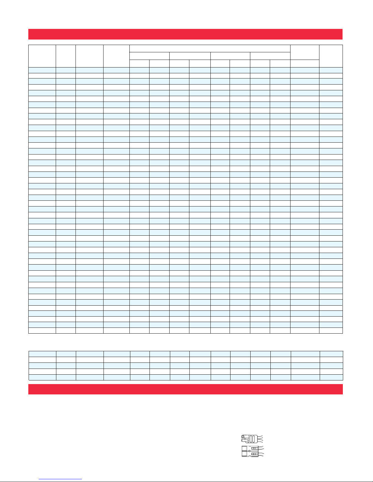
SPECIFICATIONS
SEALED LEAD-ACID BATTERIES
The PSG Series of batteries are models which correspond in size to Gates (Hawker-Sidley) batteries of the same voltage and capacity:
TERMINALS
F1
FASTON
0.187” x
0.032” quick
disconnect
tabs
F2
FASTON
0.250” x
0.032” quick
disconnect
tabs
P
FASTON
polarized:
Positive: “F
2”
Negative: “F
1”
PC
Pressure
contacts
SPRING
Spring terminals
for positive
and negative
contacts
NB
Terminal post
(lead alloy or tinplated brass with
5 mm Nut & Bolt
on
6200, 6360,
12180, 12260,
12280; with 6 mm
Nut & Bolt on
12400
HP
Heavy duty
post (lead alloy)
with
7.6 mm
diameter hole.
WL
Insulated, stranded wire leads terminated with:
• Molex Housing
5264-02 & 5263-PBT plug on PS-605
• AMP Housing 1-480318-0 & 8116-1 on 640 WL and 1208
• “250” female FASTON on 682 WL
TS/TH
• S-connector on 695 TS and 6120 TS toy batteries
• H-connector on
695 TH and 6120 TH toy batter-
1
PSG-
450 4 5.0 250 3.54 90 1.94 49 2.87 73 2.87 73 1.7 0.8
F
2
PSG-
480 4 8.0 400 3.54 90 1.94 49 4.00 102 4.00 102 2.5 1.1
F
2
PSG-
625 6 2.5 125 4.15 105 1.63 41 2.70 68 2.70 68 1.5 0.7
F
1
PSG-
650 6 5.0 250 5.28 134 1.94 49 3.00 76 3.00 76 2.5 1.1
F
2
PSG-
680 6 8.0 400 5.28 134 1.94 49 3.99 101 3.99 101 3.7 1.7
F
2
Nominal Discharge DIMENSIONS
Std.
Model
Nominal Capacity@ Current@
Length Width Height Ht. Over Terminal
Weight
Termi-
Voltage 20 hr.rate 20 hr.rate
nals
V A.H. mA
in. mm in mm in. mm in. mm lbs. kg.
PS
-260 2 6.0 300 1.97 50 1.34 34 3.94 100 4.13 105 0.90 0.41
F
1
PS
-445 4 4.5 225 1.89 48 2.09 53 3.70 94 3.86 98 1.4 0.65
F
2
PS
-470 4 7.0 350 2.52 64 2.08 53 3.70 94 3.92 100 1.9 0.9
F
1
PS
-490 4 9.0 450 3.97 101 1.73 44 3.74 95 4.02 102 2.8 1.28
F
2
PS
-4100 4 10.0 500 4.02 102 1.97 50 3.72 94 3.92 100 3.1 1.4
F
1
PS
-605 6 0.5 25 2.24 57 0.55 14 1.97 50 1.97 50 0.2 0.09 WL
PS
-610 6 1.0 50 2.00 51 1.65 42 2.00 51 2.20 56 0.6 0.3
F
1
PS
-612 6 1.3 65 3.82 97 0.94 24 2.00 51 2.19 56 0.6 0.3
F
1
PS
-630 6 3.0 150 5.28 134 1.34 34 2.35 60 2.56 65 1.5 0.7
F
1
PS
-632 6 3.2 160 2.60 66 1.30 33 4.65 118 4.80 122 1.5 0.7
F
1
PS
-640 6 4.5 225 2.76 70 1.89 48 4.02 102 4.25 108 1.95 0.9F1
or WL
PS
-650
L
6 5.0 250 2.63 67 2.63 67 3.78 96 4.28 109 2.0 0.9
Spring
PS
-665 6 6.5 325 3.86 98 2.20 56 4.05 103 4.05 103 3.0 1.4
P
PS
-670 6 7.0 350 5.95 151 1.34 34 3.70 94 3.86 98 3.0 1.4
F
1
PS-
682 6 8.0 400 3.86 98 2.20 56 4.65 118 4.65 118 3.3 1.5F1
or WL
PS
-695 6 9.5 475 4.26 108 2.75 70 5.54 141 5.54 141 4.9 2.2
P
PS-
695Toy 6 9.5 475 4.26 108 2.75 70 5.54 141 5.54 141 4.9 2.2 TS or TH
PS
-6100 6 10.0 500 5.95 151 2.00 51 3.70 94 3.86 98 4.6 2.1F1
or F
2
PS
-6120 6 12.0 600 4.26 108 2.75 70 5.54 141 5.54 141 5.2 2.4
P
PS-
6120Toy 6 12.0 600 4.26 108 2.75 70 5.54 141 5.54 141 5.2 2.4 TS or TH
PS
-6200 6 20.0 1000 6.18 157 3.27 83 4.92 125 4.92 125 8.2 3.7
NB
PS
-6360 6 36.0 1800 6.25 159 3.35 85 6.50 165 6.95 176 13.8 6.2 F2 or NB
PS
-832 8 3.2 160 5.28 134 1.42 36 2.49 63 2.70 69 1.9 0.85
F
1
PS
-1208 12 0.8 40 3.78 96 0.98 25 2.42 62 2.42 62 0.8 0.35
WL
PS
-1212 12 1.2 60 3.82 97 1.65 42 2.00 51 2.13 54 1.3 0.6
F
1
PS
-1220 12 2.2 110 7.01 178 1.34 34 2.36 60 2.56 65 1.9 0.85
F
1
PS
-1223 12 2.3 115 7.17 182 0.94 24 2.42 62 2.42 61.5 1.76 0.8
PC
PS-
1229 12 2.9 145 7.01 178 1.34 34 2.36 60 2.56 65 2.2 1.0
F
1
PS-
1230 12 3.0 150 5.23 134 2.64 67 2.36 60 2.60 66 2.6 1.2
F
1
PS-
1242 12 4.5 225 3.54 90 2.76 70 4.02 102 4.25 108 3.8 1.7
F
1
PS-
1252 12 5.0 250 3.54 90 2.76 70 4.02 102 4.25 108 4.2 1.9
F
2
PS-
1270 12 7.0 350 5.95 151 2.56 65 3.70 94 3.86 98 5.7 2.6
F
1
PS-
1282 12 8.0 400 3.86 98 4.40 112 4.65 118 4.65 118 6.7 3.0
F
1
PS-
12100 12 10.0 500 5.95 151 4.00 102 3.70 94 3.86 98 9.2 4.2F1
or F
2
PS-
12120 12 12.0 600 5.95 151 3.86 98 3.70 94 3.94 100 9.0 4.1
F
2
PS-
12120L12 12.0 600 8.38 213 2.75 70 5.50 140 5.50 140 10.7 4.8
P
PS-
12180 12 18.0 900 7.13 181 2.99 76 6.57 167 6.57 167 13.1 5.9 F2 or NB
PS-
12260 12 26.0 1300 6.89 175 6.54 166 4.95 126 4.95 126 20.8 9.4 F2 or NB
PS-
12280 12 28.0 1400 6.54 166 4.95 126 6.89 175 6.89 175 20.8 9.4
NB
PS-
12330* 12 33.0 1650 7.70 196 5.19 132 6.10 155 6.85 174 26.5 12.0
HP
PS-
12400 12 40.0 2000 7.72 196 6.42 163 6.85 174 6.85 174 30.5 13.8
NB
PS-
12550* 12 55.0 2750 9.50 241 5.45 138 8.10 206 8.95 227 41.1 18.7
HP
PS-
12600* 12 60.0 3000 10.25 260 6.60 168 8.20 208 9.45 240 54.4 24.7
HP
PS-
12750* 12 75.0 3750 10.25 260 6.60 168 8.20 208 9.45 240 55.1 25.0
HP
PS-
12800* 12 80.0 4000 12.00 305 6.60 168 8.20 208 9.45 240 62.4 28.4
HP
PS
-
121000* 12 100.0 5000 12.00 305 6.60 168 8.20 208 9.45 240 65.7 29.8
HP
* Also available with handle. To order, add “H” to model number. Note: for 12550H, 12600H, 12750H, 12800H, and 121000H overall length increases.
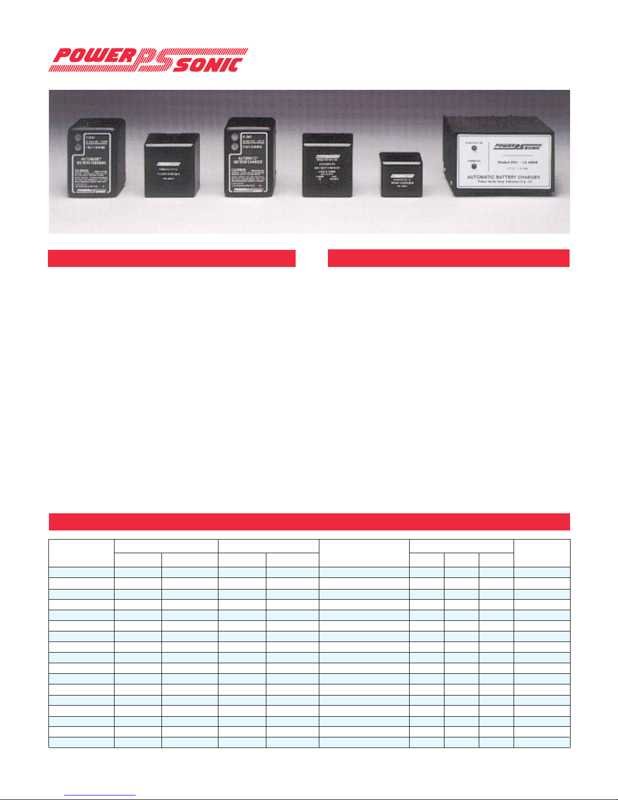
CHARACTERISTICS
Electronically regulated - current limited chargers for
sealed lead-acid type batteries.
Wall mount plug-in design for 250, 300, 500, 800 series
and 61000A; counter top design for 241000A, 2000, 4000
and 10Aseries.
Operating temperature range: 32°F – 104°F (0°C – 40°C).
Input voltage: 1 10/120VAC, 60Hz. PSC-122000Aand PSC-
241000A can be switched to accept 220/230 VAC, 50Hz.
LED indicators on “A” -type chargers – 250 & 500 series:
“POWER ON” and “CHARGING MODE” (ON for high-rate
charging, OFF when float charging). 300, 800, 1000, 2000,
4000,
and 10A series: “FLOAT” to indicate charging at float
voltage, “FAST CHARGE” to indicate high-rate charging.
Hi-impact resistant thermo-plastic housing for 250, 300,
500, and 800
series; metal housing for 1000, 2000, 4000,
and 10Aseries.
Screw-type terminals for 250 & 500 series, I/O cord with
battery connectors for 300, 800, 1000, 2000, 4000 and
10A series chargers.
“F” Series: Float chargers are designed to provide optimum life for batteries used in standby applications where
charging is continuous. The chargers deliver a constant
voltage of 2.25 to 2.30 volts per cell which allow the battery to seek its own current level and maintain itself in a
fully charged condition. This series is best suited for
burglar and fire alarm equipment, emergency lighting,
memory protection, or UPS systems where the battery
serves as back-up power to the AC source.
“A” Series: Automatic dual rate chargers sense battery
requirements and automatically switch from the fast
charge to float mode, or vice versa. LED’s provide
visual indication of the charging mode. Automatic
chargers combine the advantages of float and cycle
chargers; recharge time is short yet batteries are safe
from being overcharged. This charger is ideal for cyclic
applications where recharge time is critical and the
battery may be left on charge indefinitely. As a result
charging is fool-proof.
SPECIFICATIONS
SLA Battery Chargers
8
FEATURES
Output Voltage (V) Output Current (A) Dimensions (in.)
Weight
Model Type
Nominal Range Nominal Maximum Length Width Height (lbs.)
PSC-
6250
F
6 6.83 .30 .60
Fixed volt. float
2.20 1.96 1.88 0.5
PSC-
6250
A
6 6.75/7.35 .30 .60
Dual volt. auto.
2.20 1.96 1.88 0.5
PSC-
6300
A
6 6.84/7.35 .30 .30
Dual volt. auto.
2.75 2.75 3.75 1.36
PSC-
6500
A
6 6.75/7.35 .60 .75
Dual volt. auto.
2.55 1.88 2.89 0.8
PSC-
61000
A
6 6.84/7.35 1.00 1.00
Dual volt. auto.
2.75 2.75 3.75 1.36
PSC-
64000
A
6 6.75/7.35 3.50 4.00
Dual volt. auto.
5.70 5.80 3.30 6.0
PSC-
12250
F
12 13.65 .25 .40
Fixed volt. float
2.20 1.96 1.88 0.5
PSC-
12250
A
12 13.50/14.70 .25 .40
Dual volt. auto.
2.20 1.96 1.88 0.5
PSC-
12300
A
12 13.68/14.70 .30 .30
Dual volt. auto.
2.75 2.75 3.75 1.36
PSC-
12500
F
12 13.65 .50 .60
Fixed volt. float
2.55 1.88 2.89 0.8
PSC-
12500
A
12 13.50/14.70 .50 .60
Dual volt. auto.
2.55 1.88 2.89 0.8
PSC-
12800
A
12 13.68/14.70 .80 .80
Dual volt. auto.
2.75 2.75 3.75 1.36
PSC-
122000
A
12 13.50/14.70 2.00 2.00
Dual volt. auto.
5.50 3.50 2.75 4.5
PSC-
124000
A
12 13.50/14.70 4.00 4.75
Dual volt. auto.
5.70 5.80 3.30 6.0
PSC-
124000
AP
12 13.50/14.70 4.00 3.50/2.50
Charger/Power Supply
5.70 5.80 3.30 6.0
PSC-
12-10
A
12 13.50/14.70 10.00 10.00
Dual volt. auto.
7.95 6.10 4.50 9.0
PSC-
241000
A
24 27.00/29.40 1.00 1.00
Dual volt. auto.
5.50 3.50 2.75 4.5
Plates (Electrodes)
Plate construction is the key to producing a good battery.
Recognizing this, Power-Sonic utilizes the latest technology
and equipment to cast grids from a lead-calcium alloy
free of antimony. The small amount of calcium and tin in
the grid alloy imparts strength to the plate and guarantees durability even in extensive cycle service. Lead
oxide paste is added to the grid to form the electrically
active material. In the charged state, the negative plate
paste is pure lead and that of the positive lead oxide.
Both of these are in a porous or spongy form to optimize
surface area and thereby maximize capacity.
Separators
Power-Sonic separators are made of woven glass fiber
cloth with high heat and oxidation resistance. The material further offers superior electrolyte absorption and
retaining ability, as well as excellent ion conductivity.
Electrolyte
Immobilized dilute sulfuric acid: H2SO
4.
Container
Case material is either ABS, a high-impact proof plastic
resin, styrene, or a polypropylene-polyethylene copolymer with resistance to chemicals and flammability.
Leakproof Design & Operational Safety
Power-Sonic batteries have been approved for shipment
by air, both by D.O.T. and I.A.T.A.. U.L.’s component
recognition program for emergency lighting and power
batteries lists Power-Sonic under file numbers MH14328
and MH14838.
Terminals
Depending on the model, batteries come either with AMP
Faston type terminals made of tin plated brass, post type
terminals of the same composition with threaded nut and
bolt hardware, or heavy duty flag terminals made of lead
alloy. A special epoxy is used as sealing material surrounding the terminals.
Relief Valve
In case of excessive gas pressure build-up inside the battery (usually caused by abnormal charging) the relief
valve will open and relieve the pressure. The one-way
valve not only ensures that no air gets into the battery
where the oxygen would react with the plates causing
internal discharge, but also represents an important safety device in the event of excessive overcharge. Vent
release pressure is between 2-6 psi; the seal ring material is neoprene rubber.
Case Sealing
Depending on model, the case sealing is tongue and
groove with polyurethane, epoxy, or heat seal.
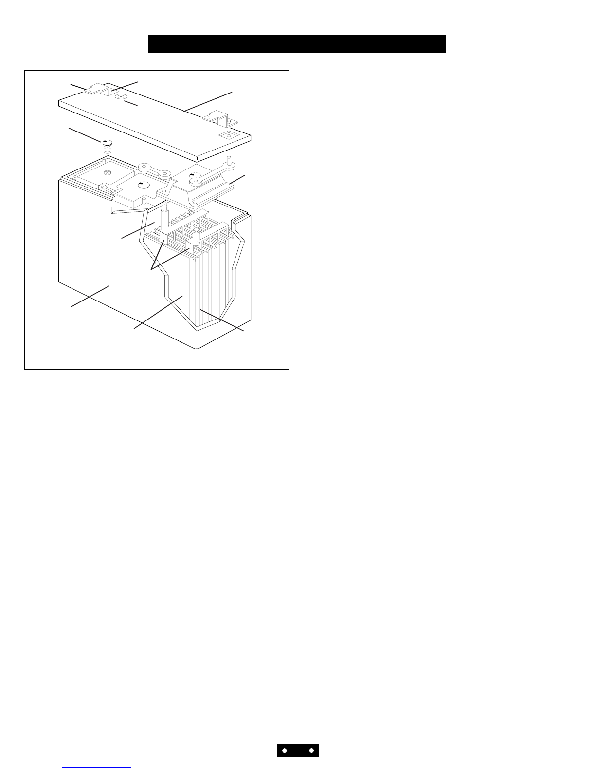
CONSTRUCTION
1
Terminal
Polarity
marking
One-way
self-sealing
vent
Cosmetic
top cover
Figure 1
Polystyrene
inner cover
Molded-in
plastic cell
divider
Two volt
element
Microporous
glass fiber
separator
Hi-impact
polystyrene case
Lead calcium
alloy grid
Color coded terminal
connection

The basic electrochemical reaction equation in a lead-acid battery can be written as follows:
Pb 2H2SO
4
PbO
2
Discharging
PbSO
4
2H2O PbSO
4
(porous lead) (sulfuric acid) (porous lead dioxide) (lead sulfate) (water) (lead sulfate)
active material electrolyte active material Charging active material electrolyte active material
of negative plate of positive plate of negative plate of positive plate
Discharge
During the discharge portion of the reaction, lead dioxide
(positive plate) and lead (negative plate) react with sulfuric acid to create lead sulfate, water and energy.
Charge
During the recharge phase of the reaction, the cycle is
reversed: the lead sulfate and water are electro-chemically converted to lead, lead oxide and sulfuric acid by an
external electrical charging source.
Oxygen Recombination
To produce a truly maintenance-free battery, it is necessary that gases generated during overcharge are recombined in a so-called “oxygen cycle”. Should oxygen and
hydrogen escape, a gradual drying out would occur,
eventually affecting capacity and battery life. During
charge, oxygen is generated at the positive and reacts
with and partially discharges the sponge lead of the negative. As charging continues, this oxygen recombines
with the hydrogen being generated by the negative,
forming water. The water content of the electrolyte thus
remains unchanged unless the charging rate is too high.
In case of rapid generation of oxygen gas exceeding the
absorbing capacity of the negative plate, the pressure
relief valve will open to release excessive gas.
Deep Discharge
The Power-Sonic battery is protected against cell shorting by the addition of a buffering agent that insures the
presence of acid ions even in a fully discharged state.
The need for expensive circuitry in the design of a system to prevent deep discharge and possible cell shorting
is thereby reduced considerably.
Power-Sonic defines “deep discharge” as one that allows
the battery voltage under load to go below the cut-off (or
“final”) voltage of a full discharge. The recommended
cutoff voltage varies with the discharge rate for a 6 volt
battery, for example, it is 5.25V at the 20-hour (0.05C)
rate, 5.10V at the 4-hour (0.2C) rate, and 4.5V at the
1/2- hour(1.0C) rate.
It is important to note that deep discharging a battery at
high rates for short periods is not nearly as severe as discharging a battery at low rates for long periods of time.
To clarify, let’s, analyze two examples:
• Battery A is discharged at the 1C rate to zero volts.
“C” for a 4 AH battery, for example, is 4 amps. Full
discharge is reached after about 30 minutes when the
battery voltage drops to 1.5V/cell. At this point, only
50% of rated capacity has been discharged (1C amps x
0.5 hrs = 0.5C Amp. Hrs.) Continuing the discharge to
zero volts will bring the total amount of discharged
ampere-hours to approximately 75% because the rapidly declining voltage quickly reduces current flow to a
trickle. The battery will recover easily from this type
of deep discharge.
• Battery B is discharged at the 0.01C rate to zero
volts. 0.01C for a 4 AH battery is 40mA. Full discharge
is reached after 100+ hours when the terminal voltage
drops to 1.75 V/cell. At this point, the battery has
already delivered 100% of its rated capacity (0.01 x
100 hrs = 1C Amp. Hrs.). Continuing the discharge to
zero volts will keep the battery under load for another
4-5 days(!), squeezing out every bit of stored energy.
This type of “deep” discharge is severe and is likely to
damage the battery. The sooner a severely discharged
battery is recharged, the better its chances to fully
recover.
THEORY OF OPERATION
2
 Loading...