

PowerSonic PS-121200 Technical Manual
H
W
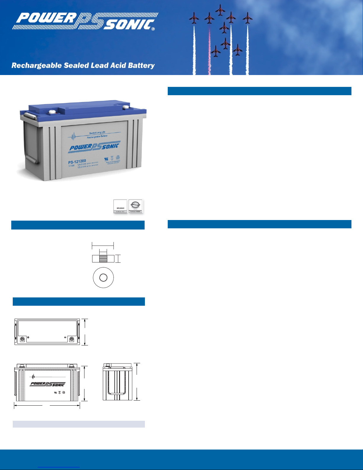
PS-121200
12 Volt 124.8 AH @ 20-hr. rate
120.0 AH @ 10-hr. rate
Sealed L ong L ife
Recharg eable Batter y
HT
PS-121200
®
Pb
12 Volt 124.8 A.H.
@ 20-hr. rate to 10.8V
MH2 084 5
NONS PI LL A B LE
120.0 A.H.
@ 10-hr. rate to 10.8V
Power-S onic Corpora tion
www.power-so nic .com
To
ensure safe and efficient operation always
refer to
the latest edition of
our T
echnical Manual, as published on
our website.
All data subject to change
without
notice.
www .seal edper forma nce.c om.au
Terminal
s
(mm)
C
Features
• Absorbent Glass Mat (AGM) technology for superior
performance
• Valve regulated, spill proof construction allows safe
operation in any position
• Power/volume ratio yielding unrivaled energy density
• Rugged impact resistant ABS case and cover (UL94-HB)
• T11 - THREADED
INSERT - 8mm STUD
Physical Dimensions: in (mm)
L: 16.14 (410) W: 6.97 (177) H: 8.86 (225) HT: 8.86 (225)
Tolerances are +/- 0.04 in. (+/- 1mm) and +/- 0.08 in. (+/- 2mm) for
height dimensions. All data subject to change without notice.
20mm
M8
7mm
• Approved for transport by air. D.O.T., I.A.T.A., F.A.A. and
C.A.B. certified
• U.L. recognized under file number MH 20845
Performance Specifications
Nominal Voltage ........................................................................ 12 volts (6 cells)
Nominal Capacity
20-hr. (6.24A to 10.50 volts) ........................................................ 124.8 AH
10-hr. (12.0A to 10.50 volts) ........................................................ 120.0 AH
8-hr. (14.3A to 10.50 volts).......................................................... 114.4 AH
5-hr. (20.64A to 10.20 volts) ..................................................... 103.2 AH
3-hr. (31.2A to 10.20 volts) ............................................................ 93.6 AH
1-hr. (73.2A to 9.60 volts) ............................................................ 73.2 AH
Approximate Weight ........................................................... 77.2 lbs. (35.0 kg)
Energy Density (10-hr. rate) .................................. 1.44 W-h/in3 (88.16 W-h/l)
Specific Energy (10-hr. rate) .............................. 18.65 W-h/lb (41.12 W-h/kg)
Internal Resistance (approx.) ..................................................... 4.0 milliohms
Max Short-Duration Discharge Current (10 Sec.).................... 374 amperes
Shelf Life (% of nominal capacity at 68°F (20°C))
1 Month ...................................................................................................... 97%
3 Months..................................................................................................... 91%
6 Months .................................................................................................... 83%
Operating Temperature Range
Charge.. ........................................................... -4°F (-20°C) to 122°F (50°C)
Discharge ....................................................... -40°F (-40°C) to 140°F (60°C)
Case ...................................................................................................... ABS Plastic
Power-Sonic Chargers ................................................................................... n/a
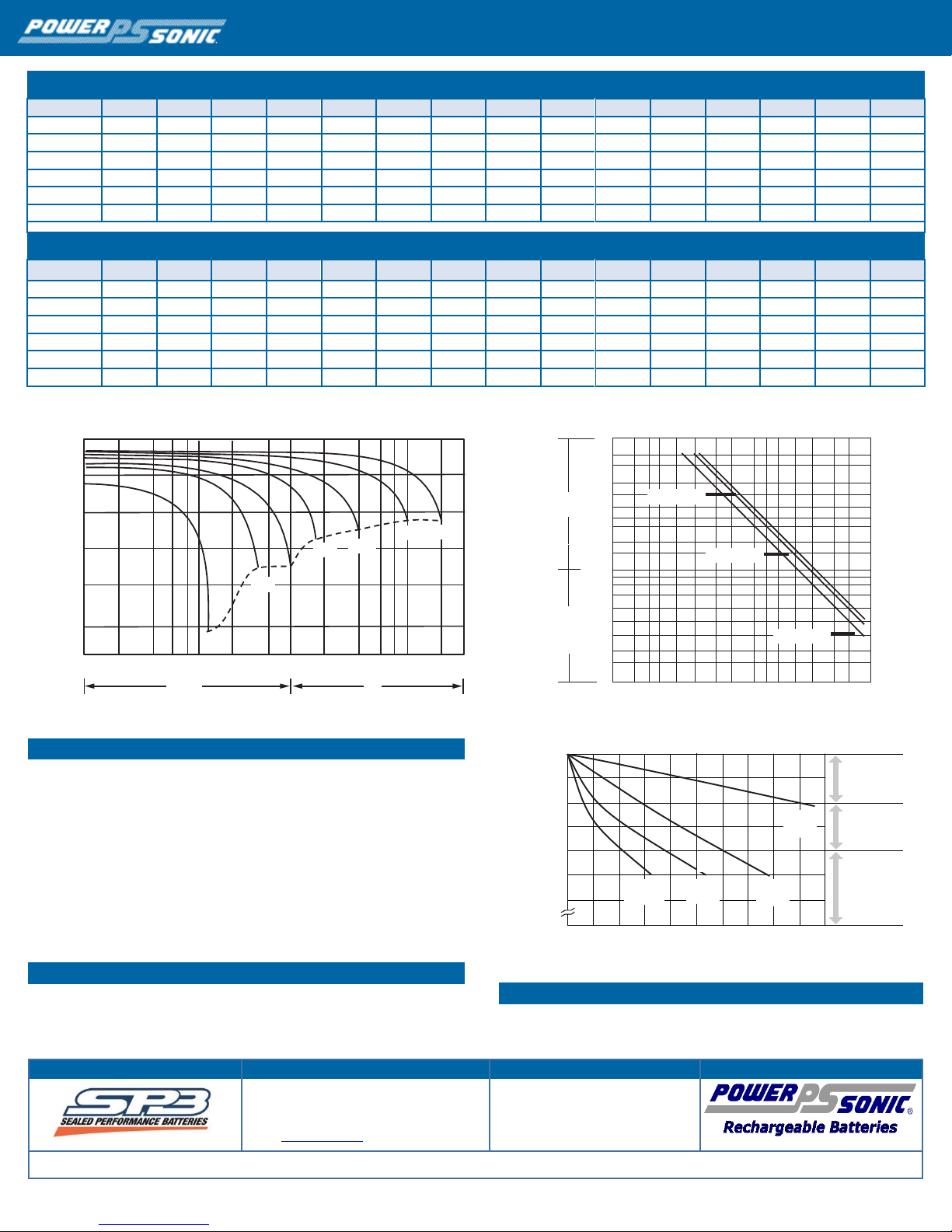
CONSTANT CURRENT DISCHARGE (Amperes) at 77° F (25° C)
Final Voltage
5 min
10 min
15 min
20 min
30 min
45 min
1H
2H
3H
4H
5H
6H
8H
10H
20H
1.85V
236.21
185.7
157.9
132.13
104.99
79.46
65.09
36.00
28.50
23.30
18.80
16.30
13.30
11.60
6.18
1.80V
317.05
237.2
190.8
156.17
123.85
92.46
72.91
39.30
30.70
24.80
20.10
17.50
14.10
12.00
6.24
1.75V
357.42
260.7
208.4
168.02
128.57
95.91
76.24
40.80
31.20
25.40
20.60
18.00
14.30
12.10
6.30
1.70V
393.64
284.2
222.5
176.52
133.86
99.70
78.66
42.40
32.10
26.10
21.20
18.40
14.50
12.20
6.42
1.65V
434.01
306.7
236.6
187.60
141.22
102.24
81.30
43.60
33.50
27.00
21.80
18.80
14.70
12.50
6.50
1.60V
478.74
332.9
253.0
199.80
149.04
106.49
84.18
45.10
34.50
27.80
22.50
19.20
14.90
12.60
6.54
CONSTANT POWER DISCHARGE (Watts/Cell) at 77° F (25° C)
Final Voltage
5 min
10 min
15 min
20 min
30 min
45 min
1H
2H
3H
4H
5H
6H
8H
10H
20H
1.85V
431.82
343.0
294.6
249.0
200.1
152.72
125.46
70.0
55.5
45.5
36.8
32.1
26.2
22.4
12.2
1.80V
573.51
433.1
351.2
290.0
232.5
176.20
139.84
75.9
59.4
48.3
39.3
34.3
27.7
23.7
12.3
1.75V
632.84
468.3
378.9
309.0
239.3
181.10
145.59
78.4
60.3
49.2
40.2
35.1
28.1
23.9
12.4
1.70V
677.58
498.9
398.9
322.2
247.7
187.70
149.73
81.3
61.9
50.4
41.1
35.8
28.5
24.1
12.7
1.65V
736.57
533.4
420.9
339.8
259.2
190.70
153.64
83.1
64.2
52.0
42.1
36.5
28.8
24.6
12.8
1.60V
793.62
565.9
442.7
358.0
271.7
197.60
158.20
85.5
65.9
53.4
43.4
37.2
29.1
24.8
12.9
Contact Information
DOMESTIC SALES
www.sealedperformance.com.au
Tel: (07) 3386 1102
1 Ant Road, Yatala
Fax: (07) 3102 9913
Brisbane QLD 4207
sales@spb.net.au
© 2015. Power-Sonic Corporation. All rights reserved. All trademarks are the property of their respective owners.
0810 1M
240
12
6.3
48
24.6
72
120
PS-121200 12 Volt 124.8 AH @ 20-hr. rate, 120 AH @ 10-hr. rate
®
0°C ( 32°F)
40°C (104°F)
25°C ( 77°F)
Terminal
Voltage (V)
Capacity
Rete
ntion
Rat
io
(%)
Discharg
e Time
(min) (h)
13 .0
Discharge Characteristics
12 .0
11 .0
10 .0
9.0
8.0
2 4
6 8 10
min
20
40 60
2 4
6 8 10 20
h
Discharge Time
Charging
Cycle Applications: Limit initial current to 36.0A. Charge until battery voltage
(under charge) reaches 14.4 to 14.7 volts at 68°F (20°C). Hold at 14.4 to 14.7
volts until current drops to under 1.20A. Battery is fully charged under these
conditions, and charger should be disconnected or switched to “float” voltage.
“Float” or “Stand-By” Service: Hold battery across constant voltage source of
13.5 to 13.8 volts continuously. When held at this voltage, the battery will seek its
own current level and maintain itself in a fully charged condition.
Note: Due to the self-discharge characteristics of this type of battery, it is
imperative that they be charged within 6 months of storage, otherwise permanent
loss of capacity might occur as a result of sulfation.
Chargers
Power-Sonic offers a wide range of chargers suitable for batteries up to 100AH.
Please refer to the Charger Selection Guide in our specification sheets for “C-Series
Switch Mode Chargers” and “Transformer Type A and F Series”. Please contact our
Technical department for advice if you have difficulty in locating suitable models.
Discharge Time vs. Discharge Current
10
9
8
7
6
5
4
3
2
60
50
40
30
20
100
80
60
40 (104
0
Further Information
Please refer to our website www.power-sonic.com for a complete range of useful
downloads, such as product catalogs, material safety data sheets (MSDS), ISO
certification, etc..
10
8
6
4
0
2 5 7 11 12 14 17 30 50 70 120 240 360 600
Discharge Current (A)
Shelf Life & Storage
0 2 4 6 8 10
40oC
Standing Period (Months)
30oC
o
(86 F)
F)
5oC
(41oF)
o
20oC
(68oF)
12 14 16 18 20
Charging is not
necessary unless
100% of capacity
is required.
Charging before
use is necessary
to help recover
full capacity.
Charge may fail
to restore full
capacity. Do not
let batteries reach
this state.
 Loading...