

Power-Sonic PDC-12400 User Manual
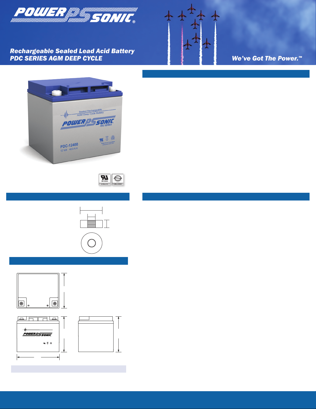
Sealed Rechargeable
AGM Deep Cycle Battery
PDC SERIES
PDC-12400
12 Volt 40.0 A.H.
Power-Sonic Corporation
B
A
T
T
E
R
Y
M
U
S
T
B
E
R
E
C
Y
C
L
E
D
Pb
NONSPILLABLE
www.power-sonic.com
MH20845
®
L
HT H
W
PDC-12400
16mm
6mm
M6
12 Volt 40.0 AH @ 20-hr. rate
38.0 AH @ 10-hr. rate
Features
Absorbent Glass Mat (AGM) technology for superior
•
performance
Valve regulated, spill proof construction allows safe
•
operation in any position
Oversize negative plates and a specialized paste
•
formulation provide true deep cycle performance.
Special additives in the paste ensure superior
•
performance in deep discharge situations.
Power/volume ratio yielding unrivaled energy density
•
Rugged impact resistant ABS case and cover (UL94-HB)
•
Approved for transport by air. D.O.T., I.A.T.A., F.A.A. and
•
C.A.B. certied
•
U.L. recognized under le number MH 20845
Terminals (mm)
Performance Specications
Nominal Voltage ........................................................................ 12 volts (6 cells)
Nominal Capacity
T6: Threaded insert w.
•
6 mm stud fastener
20-hr. (2.00A to 10.50 volts) ..........................................................
10-hr. (3.80A to 10.50 volts) .......................................................... 38.0 AH
8-hr. (4.65A to 10.50 volts) ........................................................... 37.2 AH
5-hr. (6.67A to 10.20 volts) ..........................................................
1-hr. (24.5A to 9.00 volts) .............................................................
Physical Dimensions: in (mm)
15-min. (75.0A to 9.00 volts) .............................................................. 18.7 AH
Approximate Weight ........................................................... 32.0 lbs. (14.5 kg)
Energy Density (20-hr. rate) ................................. 1.35 W-h/in3 (82.46 W-h/l)
Specic Energy (20-hr. rate) .............................. 14.25 W-h/lb (31.42 W-h/kg)
Internal Resistance (approx.) ..................................................... 9.0 milliohms
Max Discharge Current (7 Min.) ................................................ 114 amperes
Max Short-Duration Discharge Current (10 Sec.) ................... 380 amperes
Shelf Life (% of nominal capacity at 68°F (20°C))
1 Month
3 Months ..................................................................................................... 91%
6 Months .................................................................................................... 83%
Operating Temperature Range
L: 7.76 (197) W: 6.50 (165) H: 6.69 (170) HT: 6.69 (170)
Tolerances are +/- 0.04 in. (+/- 1mm) and +/- 0.08 in. (+/- 2mm) for
height dimensions. All data subject to change without notice.
To ensure safe and efcient operation always refer to the latest edition of our Technical Manual, as published on our website.
All data subject to change without notice.
Charge ..
Discharge ....................................................... -40°F (-40°C) to 140°F (60°C)
Case ...................................................................................................... ABS Plastic
Power-Sonic Chargers ............................................................. PSC-124000A-C
40.0 AH
33.3 AH
24.5 AH
...................................................................................................... 97%
........................................................... -4°F (-20°C) to 122°F (50°C)
www.power-sonic.com
PDC-12400 12 Volt 40.0 AH @ 20-hr. rate, 38.0 AH @ 10-hr. rate
®
1 2
4
6 8
10
20
40
60
2
4 6 8 10 20
min
h
4.0
4.5
5.0
5.5
6
6V Battery
(V)
12V Battery
(V)
.0
6.5
0
4
8
12
16 20
24
28
% (A) (V/cell)
Terminal Voltage (V)
Temperature: 25°C
Charge
Volume
Charging
Current
Charged
Voltage
Charge at 0.1C Amp Initial Charging Current and
2.45V/Cell Constant Voltage at 25°C
Discharge Time
Charging Time (Hours)
13.0
12.0
120
0.1C
0.08C
0.06C
0.04C
0.02C
2.5
2.4
2.3
2.2
2.1
0C
100
80
60
40
20
11.0
10.0
9.0
8.0
Charged Volume
Charge Voltage
(Constant 2.45V/Cell)
After 50% Discharge
After 100% Discharge
Charging Current
(Initial at 0.1C Amp)
2.04A
3.8A
8.13A
13.9A
24.5A
41.8A
98.8A
144A
0 200 4 00 6 0 0 80 0 1000 1200 140 0 16 00 1 8 00
20
40
60
80
100
120
0
0
4
8
12
16 20
24
28
% (A) (V/cell)
Capacity (%)
Charge
Volume
Charging
Current
Charged
Voltage
Charge at 0.1C Amp Initial Charging Current and
2.45V/Cell Constant Voltage at 25°C
Charging Time (Hours)
Number of Cycles
100%
DOD
50%
DOD
30%
DOD
Testing condition
Discharging:current 0.17C (FV 1.7V/cell);
Charging:current 2.45V/cell,max. 0.25CA;
Charging volume:125% of discharged capacity.
120
0.1C
0.08C
0.06C
0.04C
0.02C
2.5
2.4
2.3
2.2
2.1
0C
100
80
60
40
20
Charged Volume
Charge Voltage
(Constant 2.45V/Cell)
After 50% Discharge
After 100% Discharge
Charging Current
(Initial at 0.1C Amp)
1 2
4
6 8
10
20
40
60
2
4 6 8 10 20
min
h
4.0
4.5
5.0
5.5
6
6V Battery
(V)
12V Battery
(V)
.0
6.5
0 200 4 00 6 0 0 80 0 1000 1200 140 0 16 00 1 8 00
20
40
60
80
100
120
0
-
20
-10
0
10 20
30 40
50
0
20
40
60
80
100
120
0.0 5CA
0.1 0 CA
0.2 0CA
1CA
0.5 CA
2CA
3CA
0
4
8
12
16 20
24
28
% (A) (V/cell)
Terminal Voltage (V)
Capacity Ratio (%)
Capacity (%)
Temperature(°C)
Temperature: 25°C
Charge
Volume
Charging
Current
Charged
Voltage
Charge at 0.1C Amp Initial Charging Current and
2.45V/Cell Constant Voltage at 25°C
Discharge Time
Charging Time (Hours)
Number of Cycles
100%
DOD
50%
DOD
30%
DOD
Testing condition
Discharging:current 0.17C (FV 1.7V/cell);
Charging:current 2.45V/cell,max. 0.25CA;
Charging volume:125% of discharged capacity.
13.0
12.0
120
0.1C
0.08C
0.06C
0.04C
0.02C
2.5
2.4
2.3
2.2
2.1
0C
100
80
60
40
20
11.0
10.0
9.0
8.0
Charged Volume
Charge Voltage
(Constant 2.45V/Cell)
After 50% Discharge
After 100% Discharge
Charging Current
(Initial at 0.1C Amp)
2.04A
3.8A
8.13A
13.9A
24.5A
41.8A
98.8A
144A
1 2
4
6 8
10
20
40
60
2
4 6 8 10 20
min
h
4.0
4.5
5.0
5.5
6
6V Battery
(V)
12V Battery
(V)
.0
6.5
0 200 4 00 6 0 0 80 0 1000 1200 140 0 16 00 1 8 00
20
40
60
80
100
120
0
-
20
-10
0
10 20
30 40
50
0
20
40
60
80
100
120
0.0 5CA
0.1 0 CA
0.2 0CA
1CA
0.5 CA
2CA
3CA
8
10
12
0
4
6
60
80
10 0
0
2
20
40
A
B
C
0
4
8
12
16 20
24
28
% (A) (V/cell)
Terminal Voltage (V)
Capacity Ratio (%)
Capacity (%)
Remaining Capacity (%)
Temperature(°C)
Temperature: 25°C
Charge
Volume
Charging
Current
Charged
Voltage
Charge at 0.1C Amp Initial Charging Current and
2.45V/Cell Constant Voltage at 25°C
Discharge Time
Charging Time (Hours)
Number of Cycles
Storage Time (Months)
A
B
C
10°C
100%
DOD
50%
DOD
30%
DOD
30°C
40°C
No supplementary charge required
(Carry out supplementary charge before use if 100% capacity is required.)
Supplementary charge required before use.Optional charging way as below:
1.Charged for above 3 days at limted current 0.25CA and constant volatge 2.25V/cell.
2.Charged for above 20hours at limted current 0.25CA and constant volatge 2.45V/cell.
3.Charged for 8~10hours at limted current 0.05CA .
Supplementary charge may often fail to recover the capacity.
The battery should never be left standing till this is reached
25°C
Testing condition
Discharging:current 0.17C (FV 1.7V/cell);
Charging:current 2.45V/cell,max. 0.25CA;
Charging volume:125% of discharged capacity.
13.0
12.0
120
0.1C
0.08C
0.06C
0.04C
0.02C
2.5
2.4
2.3
2.2
2.1
0C
100
80
60
40
20
11.0
10.0
9.0
8.0
Charged Volume
Charge Voltage
(Constant 2.45V/Cell)
After 50% Discharge
After 100% Discharge
Charging Current
(Initial at 0.1C Amp)
2.04A
3.8A
8.13A
13.9A
24.5A
41.8A
98.8A
144A
0
4
8
12
16 20
24
28
% (A) (V/cell)
Charge
Volume
Charging
Current
Charged
Voltage
Charge at 0.1C Amp Initial Charging Current and
2.45V/Cell Constant Voltage at 25°C
Charging Time (Hours)
120
0.1C
0.08C
0.06C
0.04C
0.02C
2.5
2.4
2.3
2.2
2.1
0C
100
80
60
40
20
Charged Volume
Charge Voltage
(Constant 2.45V/Cell)
After 50% Discharge
After 100% Discharge
Charging Current
(Initial at 0.1C Amp)
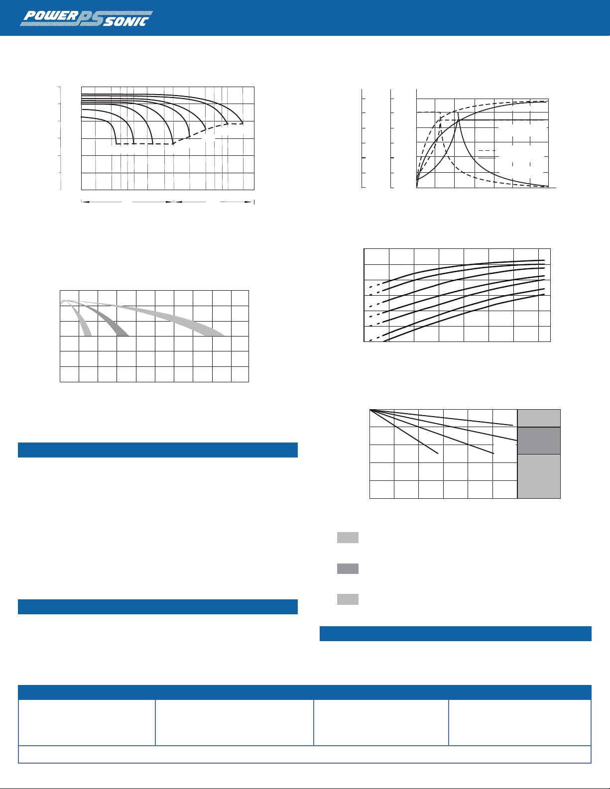
Discharge Characteristics
Cycle Life in Relation to Depth of Discharge
Charging Characteristics (Cycle Use)
Temperature Effects in Relation to Battery Capacity
Self Discharge Characteristics
Charging
Cycle Applications: Limit initial current to 11.4A. Charge until battery voltage
(under charge) reaches 14.4 to 14.7 volts at 68°F (20°C). Hold at 14.4 to 14.7
volts until current drops to under 407mA. Battery is fully charged under these
conditions, and charger should be disconnected or switched to “oat” voltage.
“Float” or “Stand-By” Service: Hold battery across constant voltage source of
13.5 to 13.8 volts continuously. When held at this voltage, the battery will seek its
own current level and maintain itself in a fully charged condition.
Note: Due to the self-discharge characteristics of this type of battery, it is
imperative that they be charged within 6 months of storage, otherwise permanent
loss of capacity might occur as a result of sulfation.
Chargers
Power-Sonic offers a wide range of chargers suitable for batteries up to 100AH.
Please refer to the Charger Selection Guide in our specication sheets for “C-Series
Switch Mode Chargers” and “Transformer Type A and F Series”. Please contact our
Technical department for advice if you have difculty in locating suitable models.
Contact Information
DOMESTIC SALES
Tel: +1-619-661-2020
Fax: +1-619-661-3650
national-sales@power-sonic.com
© 2012. Power-Sonic Corporation. All rights reserved. All trademarks are the property of their respective owners.
CORPORATE OFFICE • 7550 Panasonic Way • San Diego, CA 92154 • USA • Tel: +1-619-661-2020 • Fax: +1-619-661-3650
CUSTOMER SERVICE
Tel: +1-619-661-2030
Fax: +1-619-661-3648
customer-service@power-sonic.com
Further Information
Please refer to our website www.power-sonic.com for a complete range of useful
downloads, such as product catalogs, material safety data sheets (MSDS), ISO
certication, etc..
TECHNICAL SUPPORT
Tel: +1-619-661-2020
Fax: +1-619-661-3648
support@power-sonic.com
INTERNATIONAL SALES
Tel: +1-650-364-5001
Fax: +1-650-366-3662
international-sales@power-sonic.com
www.power-sonic.com
1012 1M
 Loading...