

Power-Sonic F Series User Manual
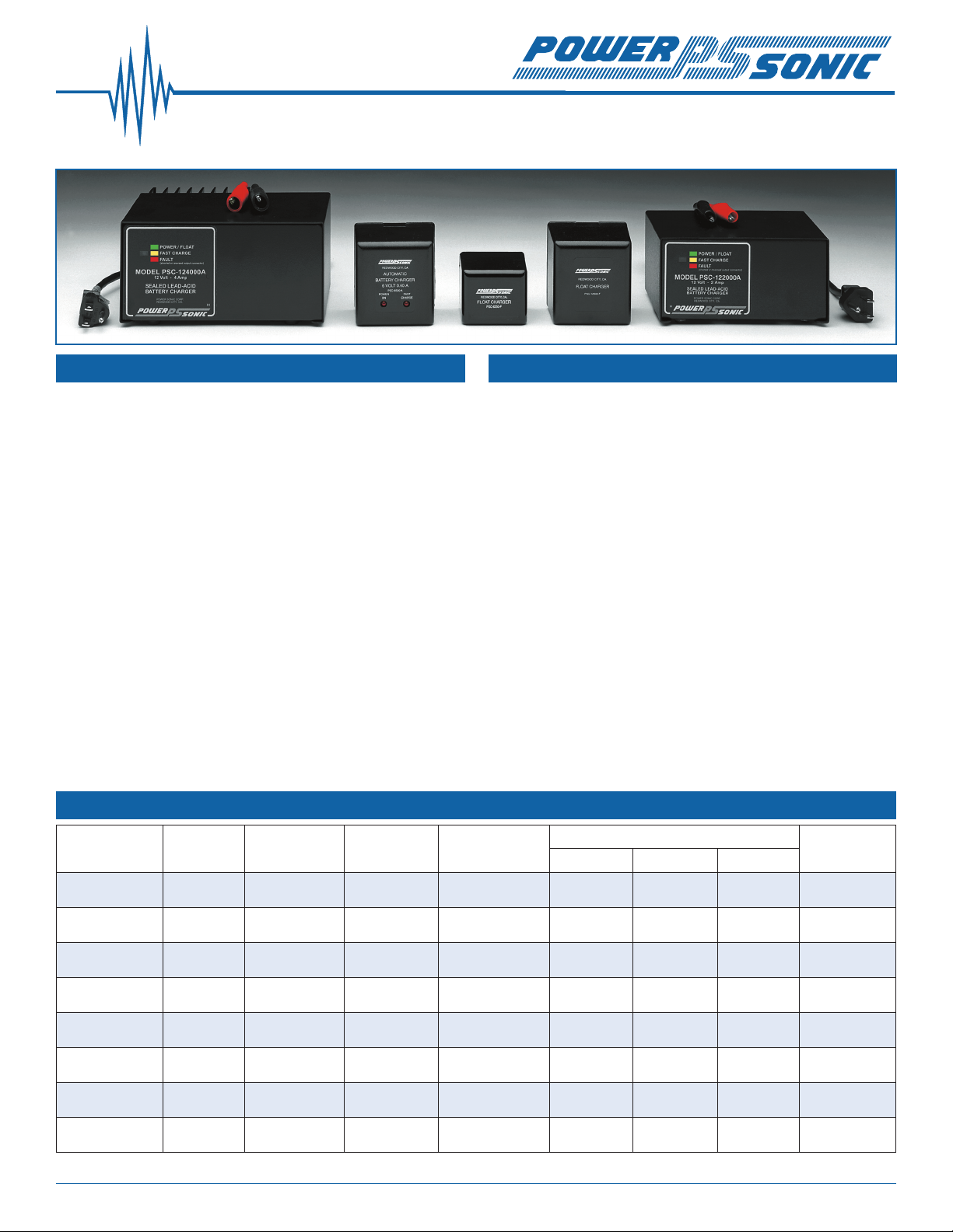
A&F Series Transformer Type Battery Chargers
FOR SLA BATTERIES
Features Operating Characteristics
Electronically regulated - current limited chargers for
sealed lead-acid type batteries.
Wall mount plug-in design for 250, 300, 500, 800 series
and 61000A; counter top design for 241000A, 2000, 4000
and 10A series.
Operating temperature range: 32ºF - 104ºF (0ºC - 40ºC).
Input voltage: 110/120 VAC, 60Hz. 122000A and 241000A
can be switched to accept 220/230 VAC, 50Hz.
LED’s: For 250A & 500A series: “POWER ON” and
“CHARGING MODE” (ON=high-rate charging, OFF=oat
charging). For 300, 800, 1000, & 10A series: “FLOAT” and
“FAST CHARGE” indicators. For 2000A, 241000A and 4000
series: single tri-color indicator.
Hi-impact resistant thermo-plastic housing for 250,
300, 500, and 800 series; metal housing for 1000, 2000,
4000, and 10A series.
Screw-type terminals for 250 & 500 series, I/O cord with
battery connectors for 300, 800, 1000, 2000, 4000 and
10A series chargers.
Specications
Model
Nominal
Voltage
Output Voltage
Float/Fast
Output
Current (mA)
“A” Series: Automatic dual rate chargers sense battery
requirements and automatically switch from the fast charge
to oat mode, or vice versa. LED’s provide visual indication
of the charging mode. Automatic chargers combine the
advantages of oat and cycle chargers; recharge time is
short yet batteries are safe from being overcharged. This
charger is ideal for cyclic applications where recharge time
is critical and the battery may be left on charge indenitely.
As a result charging is fool-proof.
“F” Series: Float chargers are designed to provide optimum
life for batteries used in standby applications where
charging is continuous. The chargers deliver a constant
voltage of 2.25 to 2.30 volts per cell which allow the battery
to seek its own current level and maintain itself in a fully
charged condition. This series is best suited for burglar
and re alarm equipment, emergency lighting, memory
protection, or UPS systems where the battery serves as
back-up power to the AC source.
Type
Dimensions: in. (mm)
Length Width Height
Weight
lbs. (kg)
PSC-6250F 6 6.83 / NA 400 Fixed volt oat 2.20 (56) 1.96 (50) 1.88 (48) 0.50 (0.23)
PSC-6250A 6 6.75 / 7.35 400 Dual Rate 2.20 (56) 1.96 (50) 1.88 (48) 0.50 (0.23)
PSC-6300A 6 6.84 / 7.35 300 Dual Rate 2.75 (69) 2.75 (70) 3.75 (95) 1.36 (0.62)
PSC-61000A 6 6.84 / 7.35 1000 Dual Rate 2.75 (70) 2.75 (70) 3.75 (95) 1.36 (0.62)
PSC-12800A 12 13.68 / 14.70 800 Dual Rate 2.75 (69) 2.75 (70) 3.75 (95) 1.36 (0.62)
PSC-122000A 12 13.50 / 14.70 2000 Dual Rate 5.55 (141) 3.60 (91) 2.89 (73) 3.80 (1.73)
PSC-124000A 12 13.50 / 14.70 4000 Dual Rate 6.65 (169) 5.30 (135) 3.40 (86) 7.40 (3.36)
PSC-124000AP 12 13.50 / 14.70 2,500/2,200 Charger/Pwr. Supply 6.65 (169) 5.30 (135) 3.40 (86) 7.40 (3.36)
We’ve Got The Power.
™
SLA Charger Selection Guide
Charger Model Max Output (mA)
PSC-6250F
PSC-6250A
†
†
Use with Battery
Voltage Capacity
400 6 0.5 - 2 AH U.L.
400 6 1 - 3 AH U.L.
U.L./CSA
Listing
PSC-6300A 300 6 1 - 3 AH CSA/NRTL*
PSC-61000A 1000 6 5 - 10 AH CSA/NRTL*
PSC-12800A 800 12 4 - 8 AH CSA/NRTL*
PSC-122000A** 2000 12 8 - 20 AH CSA
PSC-124000A** 4000 12 20 - 40 AH CSA
PSC-124000AP*** 3500 12 12- 40 AH CSA
* The “NRTL/C” mark appearing next to the CSA stamp indicates that the charger was also tested to meet U.L. requirements (UL 1310). Under the provisions of this agreement, CSA
and U.L. can now test to each others’ specications and thus obtain approval for both organizations.
** PSC-122000A and PSC-124000A can be switched to accept 115 VAC or 230 VAC input (47-63 Hz) allowing usage both here and abroad.
*** PSC-124000AP should be used when the automatic dual rate charger is used like a power supply. As such it can supply a continuous load current of up to 2.5A, yet still switch into
oat mode (13.8V) when the battery is fully charged.
Recharge time depends on the depth of the preceding
discharge and the output current of the charger. To
determine the approximate recharge time of a fully
discharged battery, divide the battery’s amp. hrs. by
the rated output current of the charger and multiply
the resulting number of hours by a factor of 1.75 to
compensate for the declining output current during the
charge cycle. If the amount of amp. hrs. discharged
from the battery is known, use it instead of the battery’s
capacity to make the calculation.
Power-Sonic does not offer chargers for batteries with capacities higher than 100 AH. If you have any queries or
difculties in locating a suitable charger for batteries above 100AH, our Technical department will be happy to help.
Notes
When charging batteries in series (positive terminal
of one battery is connected to negative of the other) all
batteries in the string will receive the same amount of
charge current, individual battery voltages may vary.
When charging batteries in parallel (positive terminals
are connected with positive terminals, negative terminals
with negative), all batteries in the string are subject to the
same charge voltage, but the charge current each battery
receives can and will vary until equalization is reached.
Contact Information
DOMESTIC SALES
Tel: +1-619-661-2020
Fax: +1-619-661-3650
national-sales@power-sonic.com
CORPORATE OFFICE • 7550 Panasonic Way • San Diego, CA 92154 • USA • Tel: +1-619-661-2020 • Fax: +1-619-661-3650
© 2010. Power-Sonic Corporation. All rights reserved. All trademarks are the property of their respective owners.
CUSTOMER SERVICE
Tel: +1-619-661-2030
Fax: +1-619-661-3648
customer-service@power-sonic.com
TECHNICAL SUPPORT
Tel: +1-619-661-2020
Fax: +1-619-661-3648
support@power-sonic.com
www.power-sonic.com
INTERNATIONAL SALES
Tel: +1-650-364-5001
Fax: +1-650-366-3662
international-sales@power-sonic.com
0810 1M
 Loading...