

Power-Sonic DCG12-65 User Manual
L
H
HT
W
Power-Sonic Corporation
B
A
T
T
E
R
Y
M
U
S
T
B
E
R
E
C
Y
C
L
E
D
Pb
NONSPILLABLE
www.power-sonic.com
MH20845
®
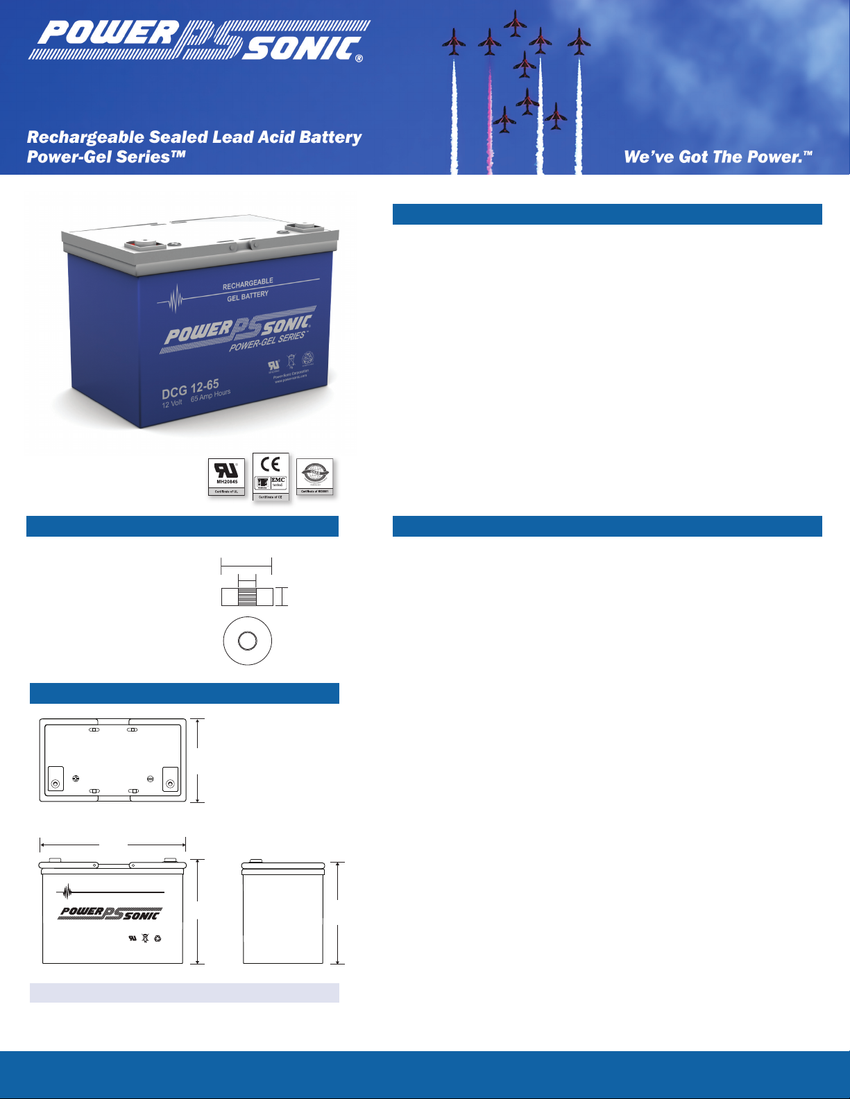
RECHARGEABLE
DCG 12-65
12 Volt 65 Amp Hours
POWER-GEL SERIES
GEL BATTERY
®
™
16mm
6mm
M6
DCG12-65
12 Volt 65 AH
Features
Thixotropic gel electrolyte for enhanced performance
•
Valve regulated, spill proof construction allows safe
•
operation in any position
Superior capabilities
•
Power/volume ratio yielding unrivaled energy density
•
Rugged ABS plastic (UL94-HB) case and cover
•
Approved for transport by air. D.O.T., I.A.T.A., F.A.A. and
•
C.A.B. certi ed
U.L. recognized - MH 20845
•
CE compliant
•
Terminals (mm)
T6: Threaded insert w.
•
6 mm stud fastener
Physical Dimensions: in(mm)
Performance Specifi cations
Nominal Voltage ............................................................................ 12 volts (6 cells)
Nominal Capacity
20-hr. (3.25A to 10.5 volts) ............................................................ 65.0 AH
10-hr. (6.00A to 10.5 volts) ............................................................ 60.0 AH
5-hr. (11.60A to 10.5 volts) .......................................................... 58.0 AH
3-hr. (17.20A to 10.5 volts) ........................................................... 51.6 AH
1-hr. (40.3A to 9.0 volts) .............................................................. 40.3 AH
Approximate Weight ................................................................ 48.0 lbs. (21.8 kg)
Energy Density (20-hr. rate) ..................................... 1.41 W-h/in3 (86.33 W-h/l)
Speci c Energy (20-hr. rate) ................................ 16.25 W-h/lb (35.83 W-h/kg)
Internal Resistance (approx.) ......................................................... 4.5 milliohms
Shelf Life (% of nominal capacity at 68°F (20°C))
1 Month ..................................................................................................... 0.97
3 Months .................................................................................................... 0.91
6 Months ................................................................................................... 0.83
Operating Temperature Range
Charge .. ........................................................... -4°F (-20°C) to 122°F (50°C)
L: 10.25 (260) W: 6.60 (168) H: 8.15 (207) HT: 8.98 (228)
Tolerances are +/- 0.04 in. (+/- 1mm) and +/- 0.08 in. (+/- 2mm)
for height dimensions. All data subject to change without notice.
To ensure safe and effi cient operation always refer to the latest edition of our Technical Manual, as published on our website.
All data subject to change without notice.
Discharge ....................................................... -40°F (-40°C) to 140°F (60°C)
Case .....................................................................................ABS Plastic (UL94 HB)
Recommended Power-Sonic Chargers .............................................................n/a
www.power-sonic.com
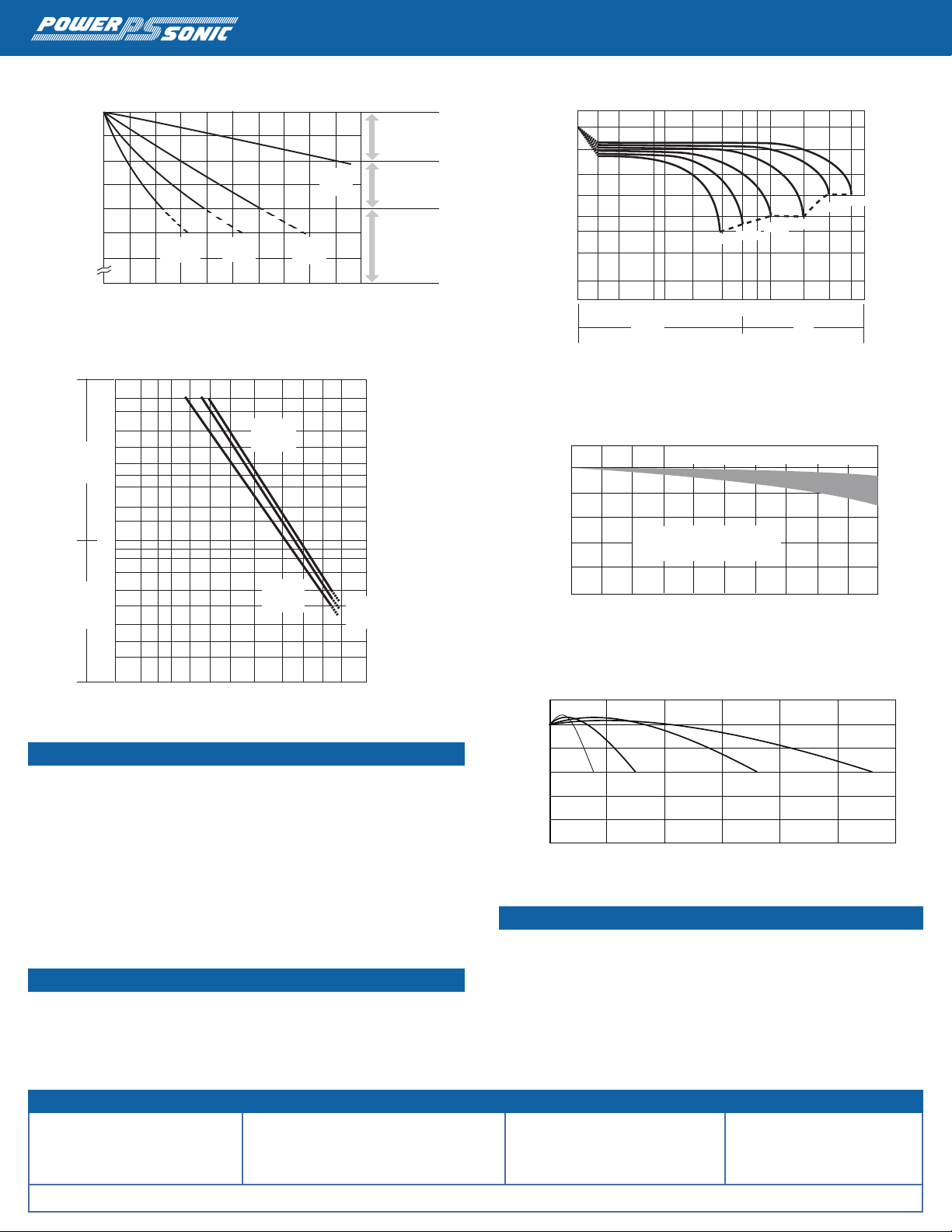
Capacity Retention Ratio (%)
Standing Period (Months)
100
80
60
40
0
0 2 4 6 8 10 12 14 16 18 20
40oC
(104oF)
30oC
(86oF)
20oC
(68oF)
5oC
(41oF)
Chargingis not
necessary unless
100% of capacity
is required.
Chargingbefore
use is necessary
to help recover
full capacity.
Chargemayfail
to restore full
capacity. Do not
let batteries reach
this state.
100
80
60
40
20
0
0 1 2 3 4
Ambient Temperature 20˚C (68˚F)
Float Charging Voltage
2.25 - 2.30 V/Cell
Retention Capacity (%)
Years
DCG12-65 12 Volt 65 AH
®
Capacity (%)
120
500
100%
DOD
50%
DOD
30%
DOD
20%
DOD
1000 1500 2000 2500 3000
100
80
60
40
20
0
Number of Cycles (Time)
10
9
8
7
6
5
4
3
2
60
50
40
30
20
10
8
6
0 1 2 4 6 7.5 9 11.5 24 45 73 105
Discharge Time
Discharge Current (A)
min h
0ºC
(32ºF)
40ºC
(104ºF)
25ºC
(77ºF)
13
12
11
10.8
10.5
9.6
9
7.8
Loading Voltage (V)
Discharge Time
0 3
min h
35 510 10 2016 30 60 2
70A
40.3A
17.2A
11.6A
6.58A
3.5A
Shelf Life & Storage
Discharge Time vs. Discharge Current
Discharge Characteristics
Life Characteristics in Stand-By Use
Charging
Cycle Applications: Limit initial current to 19.5A. Charge until battery voltage (under
charge) reaches 13.90 to 14.20 volts at 68°F (20°C). Hold at 13.90 to 14.20
volts until current drops to under 650mA. Battery is fully charged under these
conditions, and charger should be disconnected or switched to “oat” voltage.
“Float” or “Stand-By” Service: Hold battery across constant voltage source of 13.50
to 13.80 volts continuously. When held at this voltage, the battery will seek its own
current level and maintain itself in a fully charged condition.
Note: Due to the self-discharge characteristics, it is imperative that they be charged
within 6 months of storage, otherwise permanent loss of capacity might occur as a
result of sulfation.
Chargers
Power-Sonic offers a wide range of chargers suitable for batteries up to 100AH.
Please refer to the Charger Selection Guide in our specication sheets for “C-Series
Switch Mode Chargers” and “Transformer Type A and F Series”. Please contact our
Technical department for advice if you have difculty in locating suitable models.
Contact Information
DOMESTIC SALES
Tel: +1-619-661-2020
Fax: +1-619-661-3650
national-sales@power-sonic.com
CORPORATE OFFICE • 7550 Panasonic Way • San Diego, CA 92154 • USA • Tel: +1-619-661-2020 • Fax: +1-619-661-3650
CUSTOMER SERVICE
Tel: +1-619-661-2030
Fax: +1-619-661-3648
customer-service@power-sonic.com
Life Characteristics in Cyclic Use
Further Information
Please refer to our website www.power-sonic.com for a complete range of useful
downloads, such as product catalogs, material safety data sheets (MSDS), ISO
certication, etc..
www.power-sonic.com
TECHNICAL SUPPORT
Tel: +1-619-661-2020
Fax: +1-619-661-3648
support@power-sonic.com
INTERNATIONAL SALES
Tel: +1-650-364-5001
Fax: +1-650-366-3662
battery@power-sonic.com
0309 1M
 Loading...