

Page 1

Owner’s Manual
Page 2

Table of Contents
Product Introduction
Explanation of Warning Messages
Danger
Warning
Chemical Hazard
Personal Injury
Requirements for Detergents and Sanitizers
Detergents
Sanitizers
Factory Assistance
Operating Instructions
Filling The System
Rinse Water
Sanitizer Water
Adding Detergents and Sanitizers
Manual Dispensing
Auto Dispensing
Wash Cycle
Controls & Features
Starting and Stopping the Wash Action
Introducing Pots and Pans to the Power Soak
Properly Scrapping Pots and Pans
Loading and Using the Wash Sink
Loading and Washing Utensils
Unloading the Wash Sink
Rinsing Pots & Pans
Sanitizing Pots & Pans
Drying of Pots & Pans
Deep Cleaning and "Night Washing"
Wash, Rinse and Sanitizer Clean-up
Page 3
Page 4
Page 5
Pages 6-8
Pages 9-14
1
Page 3

Table of Contents - Continued
Preventive Maintenance
Troubleshooting
Routine Preventive Maintenance
Daily
Monthly
Notes
Pages 15-16
Pages 17-21
Facility Owner/Manager Section
Authorized Service Agency Section
Component Operation & Checks
Parts List
Electrical Schematic
Pump and Motor Assembly
Installation
Notes
Electrical Requirements
Providing Proper Electrical Service
Plumbing Requirements
Pages 22-30
Pages 31-32
Page 33
Pages 34-38
Pages 39-40
2
Page 4

Product Introduction
Thank you for purchasing a Power Soak ware washing system.
Your new Power Soak pot, pan and utensil washing system will provide years of
dependable, efficient and trouble-free service.
As a Power Soak owner, you will benefit in numerous ways:
• Your ware washing operation will be more efficient.
• Pots, pans and utensils will be cleaner.
• The overall level of sanitation in your scullery area will improve.
• Ware washing hours will decrease as employee morale increases.
• Chemical and water usage will decrease.
Every system is manufactured to last, with only high-quality, heavy-duty, 14 gauge
stainless steel used in its construction. All electrical components used in a Power Soak
system are of the highest quality. The faucets and drains are designed for quick filling and
emptying of the system's sinks.
At Metcraft, we take pride in manufacturing the Power Soak line and are committed to
standing behind our customers and products 100%. Should you ever need assistance, please
contact us directly at the factory by dialing 800-444-9624 or fax: 816-761-0544.
4
3
Page 5
Explanation of Warning Messages
Be sure to read, understand and follow all DANGER, WARNING, and CAUTION
messages located in this guide and on the equipment.
Danger
Personal Injury and Property Damage hazard.
May result in serious injury or death.
May cause extensive equipment damage
Warning
Property Damage Hazard.
May result in property or equipment damage.
Personal Injury Hazard
Hazard from sharp objects.
May result in serious injury or death.
Chemical Hazard
May result in serious injury or death. Instructions, labels and
Material Safety Data Sheets (MSDSs) should be supplied with all
detergents and sanitizing chemicals. The manufacturers, importers
and distributors of your cleaning chemicals are responsible for
providing this information.
Metcraft is not a chemical manufacturer, importer or distributor. Metcraft, Inc. can assist
your chemical representative but will not make specific brand recommendations.
4
Page 6

5
Page 7
Requirements for Detergents and
Sanitizers
Detergents
Remember, improper detergents may damage equipment! Use of the correct detergent in
your Power Soak system is critical to its washing performance. If you are having problems
with cleaning results, please contact the factory.
Your new system requires a low-foaming, metal/aluminum-safe
detergent that is safe for the hands. The detergent should have good
grease cutting abilities but not have an excessively high pH level.
Sanitizers
The method of sanitizing used in your Power Soak system is a "chemical sanitizing"
method. There are a number of products on the market that work well. Your chemical sales
representative should assist you in selecting the proper sanitizer for your application.
Check with your cleaning chemical provider to determine detergent concentration, sanitizer
"parts per million" (ppm) and sanitizer submersion times to meet local health codes.
Factory Assistance
If your chemical sales representative is having difficulty selecting a detergent or sanitizer,
or if you are getting poor results with the chemicals your representative has recommended,
please contact the factory at 800-444-9624.
6
Page 8

Operating Instructions
7
Page 9

Preparing the System
Filling the System
At the beginning of each day or shift, fill the sinks with water that is metered to
approximately the correct operating temperatures:
• Wash sink (115°F / 48°C)
• Rinse sink (75°F / 24°C)
• Sanitizer sink (75°F / 24°C)
All sinks should be filled to, but not above, the “waterline” marks.
Fill the wash sink (the sink with the water jets) with water that is approximately 115°F /
48°C. You can use the hot and cold taps on the faucet to adjust the water to the appropriate
temperature. A good rule of thumb is that the water should be hot to the touch but not so
hot that it is uncomfortable.
Rinse Water
If your method for rinsing wares is of the “submersion” type, fill the rinse sink (middle
sink) with water that is approximately room temperature, 75°F / 24°C. There is no need to
fill the rinse sink if your location uses a sprayer for rinsing wares.
Sanitizer Water
Fill the sanitizer sink (the last sink) with water that is approximately room temperature,
75°F / 24°C.
Your Chemical Company Should Be Aware of the
Following:
The detergent must be low foaming, metal/aluminum-safe and not excessively caustic.
Most standard sanitizers are acceptable.
8
Page 10

Adding Detergents & Sanitizers
Manual Chemical Dispensing
After the sinks have been filled with water, add the proper amount of detergent and
sanitizer. The detergent goes into the wash sink (the sink with the water jets) and the
sanitizer goes into the sanitizer sink (the last sink).
Be sure to add the proper amount of chemicals to each sink. The amount to be used should
be provided by your chemical supplier. Do not add the detergent or sanitizer to the sink
prior to or during filling.
Automatic Chemical Dispensing
Your Power Soak may be equipped with an automatic chemical dispensing system. Be
sure to follow the chemical company’s instructions regarding the use and care of the
dispenser.
Wash Cycle
Most detergents and sanitizers lose effectiveness as time goes on. Some local health
departments have requirements limiting the amount of time water can be used for cleaning
before the water should be changed. Most chemical companies recommend changing wash
water after a certain time frame. Those times vary, but are generally around four hours.
Check with your chemical provider.
Your Power Soak sink is equipped with a timer preset at four hours. This means that your
Power Soak will turn off four hours after pressing the start button.
The following steps should be taken after the sink times out:
• Empty the wash sink
• Refill with fresh water
• Add your detergent
• Press the Start button
Check with your chemical provider on how often to replace your sanitizer.
9
Page 11

10
Page 12

Controls and Features
Start Button (green)
Starts the washing action and starts the timer. Your Power Soak sink will run for four
hours after this button is pressed.
Stop Button (red)
Stops the washing action and resets the timer.
Heat Switch (black on/off switch)
Turns on power to the heat control. The heat control measures the water temperature and
decides whether to heat the water more.
Digital Display (heat control)
Not visible on all models. Shows you the current temperature of the water. This will only
display when the heat switch is on.
11
Page 13

Controls and Features - Continued
Starting and stopping the wash action
To start the wash action, press the green “START” button. A strong “rolling” wash action
should be present.
To stop the wash action, press the red “STOP” button.
Introducing Pots and Pans to the PowerSoak
Dirty pots and pans should be brought to the Power Soak in a timely manner. Do not allow
items to sit and air dry. The quicker that items are brought to the Power Soak and put in
the wash tank, the easier they are to clean!
Properly Scrapping Pots and Pans
Excess soils should be removed from the pots and pans prior to dropping them in the wash
sink.
Deposit the excess soils into a garbage can.
Some systems may have an optional pre-scrapping area with a pre-rinse spray. If so, soils
may be deposited into the scrapper sink.
12
Page 14

Controls and Features - Continued
Loading and Using the Wash Sink
The Power Soak is a “random loading” system. This means that Power Soak items are not
racked for washing. Instead, they are randomly loaded one at a time.
As items are brought to the system and scrapped, they should be immediately dropped into
the wash sink.
If there is no movement of items in the wash sink, or if items are stationary above the
waterline, the system has been overloaded and some items must be removed.
It is very important not to overload the wash sink, as it reduces the effectiveness of the
wash action.
Some pots and pans stack for storage. This is referred to as “nesting” when it occurs
during a Power Soak wash cycle. Make sure that nested items are separated and loaded one
at a time. Nested items in the wash sink will not be properly washed.
Power Soak is a “continuous motion” system. This means that the system does not operate
on a set cycle time like cabinet-type washing systems. Instead, during normal operating
hours where washing is required, the system is (normally) left running. The Power Soak is
energy efficient, and it does not cause excessive wear to leave it running continuously.
Typically, it takes between three to fifteen minutes to wash items. Some heavily soiled or
burnt-on items may take longer to clean.
13
Page 15

13
Controls & Features - Continued
Loading and Washing Utensils
Each Power Soak system comes with a utensil basket that hangs in the wash sink. All
utensils and other small wares should be loaded into and washed inside this basket.
Do not wash knives or other sharp objects in the Power Soak. Doing so may cause bodily
injury.
Unloading the Wash Sink
The employee responsible for pot washing should routinely pass by the Power Soak and
remove clean items from the wash sink.
Items that are not 100% clean can be quickly finished off with a scrub pad or dropped back
into the wash sink for additional cleaning.
Remember: it is not necessary to turn the wash action off to load or unload items from the
wash sink. There are no moving parts within the wash sink that could cause bodily harm.
14
Page 16

14
Controls & Features - Continued
Rinsing Pots and Pans
Clean items that have been removed from the wash sink should be thoroughly rinsed. This
is achieved by spraying them off or dipping them in the rinse sink (center).
It is important that any remaining detergent residue is removed from the items prior to
sanitizing.
If items are rinsed by the "dipping" method, it is important to keep the water "fresh" by
frequently draining and filling the rinse sink.
Sanitizing Pots & Pans
After items have been properly rinsed they must be sanitized in the sanitizing sink. (last).
It is necessary for each item to remain submersed in the sanitizing solution for a specific
amount of time. The amount of time varies according to the type of sanitizer being used
and local health codes.
Be sure to follow your chemical sales representative's instructions to ensure that all items
are properly sanitized.
Drying of Pots & Pans
After items have been sanitized, they should be thoroughly dried on a clean drain board or
on adjacent drying shelves.
Be sure to adhere to all local health codes and recommendations for proper drying and
stacking of items.
15
Page 17

15
Controls & Features - Continued
Deep Cleaning and "Night Washing"
Extremely soiled items and pieces of cooking equipment that require regular, intensive
cleaning can be washed in the Power Soak system overnight.
Load the items to be deep cleaned into the Power Soak's wash sink, turn the system on and
leave it running overnight.
The Power Soak will automatically shut down after the four-hour wash cycle, and the
heater in the wash tank will keep the temperature of the water at a constant 115°F until the
morning crew arrives.
Items that have been cleaned overnight can be removed, rinsed, sanitized (if necessary) and
put away or back in place.
Use your Power Soak as a "total cleaning system!" Remember, any item in your operation
that can be submersed for cleaning and is not fragile can be washed without labor in your
PowerSoak!
Here are some examples of items that are typically deep-cleaned overnight in the "Night
Wash" cycle:
• Hood Filters
• Roasting Pans
• Stove Tops
• Frying Equipment
Many other items in your operation may qualify. Be creative and set up a regular "Night
Wash" program for improved sanitation.
Wash, Rinse and Sanitizer Clean-Up
Between each water change and at the end of each night, all tanks and drain boards should
be thoroughly cleaned with hot, soapy water.
It is also recommended to wipe down all the tanks and drain boards with a sanitizing agent.
Ask your chemical provider to recommend a sanitizer for this application.
16
Page 18
Preventive Maintenance
Your system requires minimal, routine preventive maintenance. As such, the following
should be done on a routine basis to ensure that your system remains reliable:
Daily
Clean the liquid level sensors. These sensors are located on the side walls of the wash and
sanitizer tanks. They are the white plastic discs with metal centers. Clean the sensor faces
thoroughly. If cleaned regularly, a washcloth and soapy water are all that is required.
If the liquid level sensors are not cleaned regularly, the machine
may fail to operate; or it may be possible to run it without water,
which may cause serious damage to the unit.
Monthly
IMPORTANT: Turn off the power to the unit at the main breaker
prior to performing the following task!
Clean the pump motor fan shroud with a damp, soapy rag. The motor shroud is the
"vented" cover located at the end of the motor (closest to the control panel). This will
prevent grease and dust from accumulating in the cover's openings, which can obstruct the
airflow that cools the motor.
De-lime the wash sink. Simply add a de-liming agent to a sink of warm, fresh water and
run the system overnight.
Ask your chemical sales representative to recommend a specific de-liming agent.
There are no other preventive maintenance procedures that you will need to perform on
your Power Soak system. You need not be concerned about greasing the motor bearings, as
they are permanently sealed. If you have any questions regarding the preventive
maintenance procedures, please contact the factory at 800-444-9624.
17
Page 19

Notes
______________________________________________
______________________________________________
______________________________________________
______________________________________________
______________________________________________
______________________________________________
______________________________________________
______________________________________________
______________________________________________
______________________________________________
______________________________________________
______________________________________________
______________________________________________
______________________________________________
______________________________________________
______________________________________________
______________________________________________
______________________________________________
______________________________________________
______________________________________________
______________________________________________
______________________________________________
______________________________________________
______________________________________________
______________________________________________
______________________________________________
18
Page 20

Troubleshooting
19
Page 21
Facility Owner/Manager Section
The only troubleshooting procedure that the facility owner or
manager can perform is listed immediately below. All other
procedures must be performed by an authorized service agency. To
obtain the name of a recommended service agent in your area,
please call the Metcraft, Inc. Power Soak Service Department at
800-444-9624.
Pump and Heater do not work
Please perform the following in order:
• Drain the sink.
• Turn off the circuit breaker for your sink.
• Clean the liquid level sensor (LLS). This is located on the right or left inside wall
(same side as control panel) of the wash sink, behind the removable baffle. The
LLS is a white plastic disk with a silver metal center. Use warm soapy water.
• Fill the sink.
• Turn on the circuit breaker for your sink.
• Start the sink.
20
Page 22
Authorized Service Agency Section
Hazard to untrained or unauthorized personnel.
The following procedures are provided for use only by an
authorized service agency. No facility owner, manager, employee
or other unauthorized person should attempt to perform any of these
procedures. To obtain the name of a recommended service agent in
your area, please call the Metcraft, Inc. Power Soak Service
Department at 800-444-9624.
When performing troubleshooting procedures, the authorized
service agency will need to open the Power Soak system's main
electrical enclosure.
Properly close the control panel before reconnecting the circuits.
Refer to the previous checklist under the "Facility Owner / Manager
Section" before proceeding to the following checklist items:
Pump and Heater do not work
Look For Correction
1
No water in sink Fill sink with water
2
LIQUID LEVEL SENSOR dirty Clean LIQUID LEVEL SENSOR
3
No incoming power to unit Reset customer’s breaker in breaker control panel
4
Blown fuses Replace blown fuse – Refer to wiring diagram for correct fuses
5
Loose wires Tighten wires
6
LIQUID LEVEL SENSOR setting is too low See page 23
7
Defective LIQUID LEVEL CONTROL or SOCKET Check and replace as necessary
21
Page 23
If amp draw is greater than 10% of motor rating and all of above check
Authorized Service Agency Section
- Continued
Heater works – Pump does not work
Look For Correction
1
Tripped OVERLOAD Push red RESET bar on OVERLOAD
2
Loose wires Tighten wires
3
Defective START or STOP switch Check and replace as necessary
4
Defective CONTACTOR/OVERLOAD Check and replace as necessary
5
TIMER settings incorrect Check – See page 24
6
Defective TIMER Check and replace as necessary
7
Defective PUMP MOTOR Check and replace as necessary
Overload trips
Look For Correction
1 Low voltage to unit Check with Volt meter while running
2 Debris in PUMP intake Clean
3 Debris in IMPELLER Remove PUMP and clean
4 Defective CONTACTOR Check and replace as necessary
5 Defective OVERLOAD Check and replace as necessary
6 Defective PUMP MOTOR
out, then replace MOTOR
22
Page 24
Authorized Service Agency Section
- Continued
Pump works – Heater does not work
Look For Correction
1 Loose wires Tighten wires
2 Defective SWITCH Check and replace as necessary
3 Defective HEAT ELEMENT Check and replace as necessary
4 Defective HEAT CONTROL Check and replace as necessary
5 Defective THERMOCOUPLE Check and replace as necessary
6 Defective HEAT CONTACTOR Check and replace as necessary
Intermittent running
Look For
1
See 2,5,6,7 under
2
See 5, 6 under Heater Works – Pump does not work
Pump and Heater do not work
Pump leaks
Look For Correction
1 PUMP CASING PLUG loose or defective Tighten or replace
2 Defective PUMP SEAL Replace
23
Page 25
Component Operation and Checks
The following checks should only be performed by qualified
technicians using extreme caution.
Electrical hazard to untrained personnel may result in electrical
shock, burns, or death.
Heater Contactor
If there is 208v-230v across the coil and the contactor does not pull in, the contactor is
defective. If there is 208v-230v across terminals L1 and L2 and the contactor is pulled in,
but no voltage across terminals T1 and T2, the contactor is defective.
Heater Element
Check the heat element as follows:
1. TURN POWER OFF AT BREAKER PANEL.
2. Make sure the connections at terminals T1 and T2 on the heater contactor are tight
and the heater contactor is open.
3. Check the resistance between terminals T1 and T2 on the heater contactor.
Resistance should be 21 to 24 ohms. If not, the heat element is defective. If there is
no resistance, check the wiring connections in the heater box before assuming the
element is defective.
4. If there is no water in wash sink, fill until heat element is completely submerged.
5. Set test meter to read resistance and check for resistance between terminals T1 on
the heater contactor and ground and T2 on the heater contactor and ground. If there
is measured resistance to ground, the heat element is defective.
Heater ON/OFF Selector Switch
TURN POWER OFF AT BREAKER PANEL. In the "off" position, there should be no
continuity across terminals 3 and 4. In the "on" position, there should be continuity
between terminals 3 and 4. Remove the wires before checking for continuity.
Push ON / Push OFF Start and Stop Buttons
TURN POWER OFF AT BREAKER PANEL. The stop button should have continuity at
rest and no continuity when pushed in. The start button should have no continuity at rest
and continuity when pushed in. Remove the wires before checking for continuity.
24
Page 26

Component Operation and Checks
Liquid Level Control and Sensor
The liquid level control sends a trickle current (1/1000 amp) out terminal 5 to the liquid
level sensor. If there is water in the wash sink, the current passes through it to the wash
sink wall and back to the liquid level sensor to terminal 6. On some machines, the wire
from terminal 6 is hooked up to a second probe instead of the wash sink wall. Reversing
these 2 wires will not affect the operation. After the circuit is complete, a 10 second time
delay is initiated. The purpose of this delay is to prevent rapid cycling of the relay should
the water rise and fall below the sensor while the sink is filling. At the end of the time
delay, the relay in the liquid level control will close sending current to operate the various
components in the control panel. If the red "power" light on the timer is on, the liquid level
control is ok.
On some models, the sensitivity of the liquid level control is adjustable. To adjust the
sensitivity, clean the liquid level sensor, TURN POWER OFF AT BREAKER PANEL and
check the resistance between the liquid level sensor and the wash sink wall (or second
probe). It should be 25,000 to 35,000 ohms. If not, adjust the sensitivity as required.
25,000 to 35,000 ohms is generally between 0 and 1 on the dial. If there is no resistance,
the wires from terminal 5 and 6 to the liquid level sensor and sink wall are loose, or the
liquid level control or socket is defective.
If adjusting the sensitivity setting does not allow the machine to operate, the liquid level
control can be checked as follows:
1. Set sensitivity as indicated above
2. Make sure wash sink is filled to the fill line. If the red "power" light on the timer is
on, the liquid level control is ok.
3. Remove liquid level control from socket.
4. Check voltage across terminals 2 and 7 of the socket and 1 and 7 of the socket. It
should be 208v-230v. If no voltage, check the breaker, fuses, and wiring to the
socket.
5. TURN POWER OFF AT BREAKER PANEL. Make sure there is continuity
between terminal 3 of the socket and terminal 4 on the heat on/off selector switch.
If not, trace the wire and make the necessary repair.
6. Reinstall the liquid level control. Wait 10 seconds and check the voltage across
terminal 4 on the heat on/off selector switch and L2 incoming power. If no voltage,
the liquid level control or socket is defective.
25
Page 27

Component Operation and Checks
Timer
The timer controls how long the pump will run after the "start" push button is pushed in.
Two different timers have been used. They function the same but the settings differ. The
timer settings should be as follows:
MODE
RANGE
FACE NUMBERS
DIAL SETTING
When the "start" push button is pushed, the timer is activated and sends L1 power to
terminal A1 on the motor starter/overload.
The timer can be checked as follows:
1. Make sure the timer is set as indicated above.
2. If the red "power" light is on, go to step 5.
3. Check voltage across terminal 10 on the timer socket and L1 incoming power. It
should be 208v-230v. If there is no voltage, check the breaker, fuses, transformer
and wiring.
4. Check voltage across terminal 2 on the timer socket and L2 incoming power and
terminal 11 on the timer socket and L2 incoming power. It should be 208v-230v.
If there is no voltage, check the breaker, fuses, transformer, liquid level control,
stop switch and wiring. Make the necessary repair.
5. TURN POWER OFF AT BREAKER PANEL. Remove the timer from the socket.
6. Make sure there is continuity between terminal 9 on the socket and terminal 95 on
the thermal overload. If not, trace the wire and make the necessary repair.
7. Make sure there is continuity between terminal 6 on the socket and terminal 3 on
the "start" push button. If not, trace the wire and make the necessary repair.
8. Push and hold the "start" push button in and check for continuity between terminals
3 and 4 on switch. If there is no continuity, replace the "start" switch.
9. Reinstall the timer and turn power on. Wait 10 seconds for the liquid level control
to activate. The red "power" light should come on.
10. Check voltage across terminal 4 on the "start" push button and L2 incoming power.
It should be 208v-230v. If there is no voltage, trace the wire to the "stop" switch
and make the necessary repair.
11. Push and release the "start" push button. Check voltage across terminal 95 on the
thermal overload and L2 incoming power. It should be 208v-230v. The green "OP"
light should flash on the ISSC timer. The red "OUT" light should illuminate on the
IDEC timer. If there is no voltage, the time is defective.
ISSC Timer IDEC timer
SF D
HRS 10H
0 through 10 0 through 1
4 4
26
Page 28

Component Operation and Checks
Pump Contactor
The thermal overload can be checked as follows:
1. If there is 208-230v across the coil (terminals A1 and A2) and the contactor does
not pull in, the contactor is defective.
2. TURN POWER OFF AT BREAKER PANEL.
3. Remove the wires from terminals T1 and T3 on the thermal overload.
4. Push the contactor closed manually and check for continuity across pump contactor
terminals L1 and T1, L2 and T2, L3 and T3. If no continuity on any of these, the
contactor is defective.
Thermal Overload
The blue reset button should be in the down position (automatic reset). The dial should be
set at 10. The trip indicator is located between the dial and the symbols "LR2".
The thermal overload can be checked as follows:
1. TURN POWER OFF AT BREAKER PANEL. Remove the wires from terminals
95 and 96.
2. Make sure the thermal overload is not tripped. If the thermal overload is tripped,
reset it. If the thermal overload has tripped recently, you may have to wait several
minutes for it to cool down before it will reset.
3. Check for continuity across terminals 95 and 96. If no continuity, the thermal
overload is defective or the reset is tripped.
4. Make sure the T1, T2, and T3 terminals on the pump contactor
5. Remove the wires from terminal T1 and T3 on the thermal overload.
6. Check for continuity across T1 on the pump contactor and T1 on the overload, T2
on the pump contactor and T2 on the overload, T3 on the pump contactor and T3 on
the overload. If no continuity on any of these, the overload is defective.
are tight.
27
Page 29
Component Operation and Checks
Heater Controller
The heat controller controls the wash tank temperature. On some models, this display is
not visible. If the display is visible, the Heat Control is made by either Watlow, or RKC.
They function similarly, but are visually different. If the display is not visible, the Heat
Control is made by RKC.
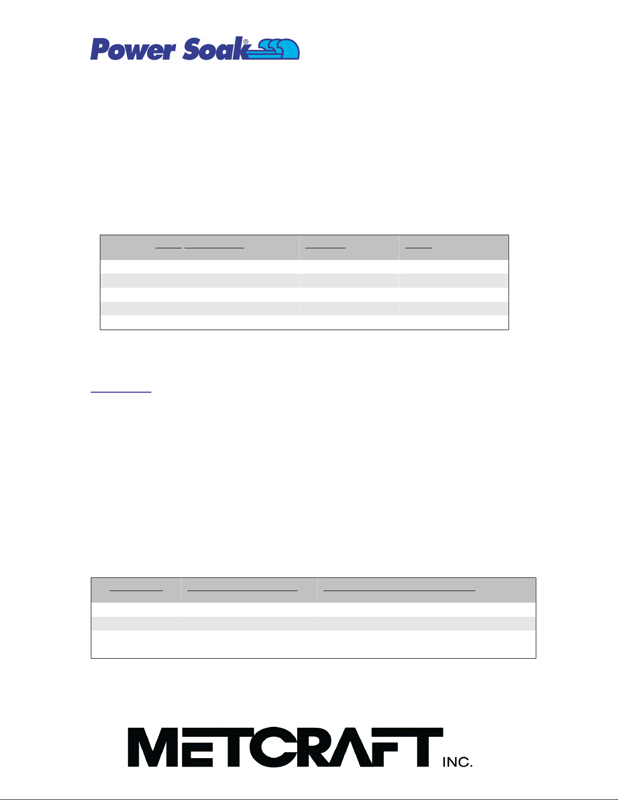
Wiring configuration
Wire Description Watlow RCK
Thermocouple red (-) Pin 1 Pin 9
Thermocouple white (+) Pin 2 Pin 8
L1 from heat switch (black) Pins 6 & 7 Pins 1 & 4
L2 from heat contactor (white) Pin 1 Pin 2
Signal to heat contactor (red) Pin 5 Pin 3
Watlow Heat Control
The red illuminated display will indicate the actual temperature on top and the set
temperature on the bottom. The set temperature is displayed when the “set” button is
pushed. To adjust the set temperature, push and hold the “set” button and push the “arrow
up” or “arrow down” button. The range of adjustment is typically 114°F to 118°F. If the
water temperature falls below 110°F, the display will flash “LO”. If the water temperature
rises above 120°F, the display will flash “hI”. The red indicator light at “2” will light
when the controller is sending current to the heater contactor.
The Watlow heat controller will display the following error messages to assist in
troubleshooting:
Note: Excessive moisture can cause these error messages.
DISPLAY PROBABLE CAUSE RECOMMENDED ACTION
Er 2 Programming error See programming on page 28
Er 4 , Er 5 Microprocessor defective Replace heat controller
Er 6 , Er7 Thermocouple defective,
loose, broken wire
Check the thermocouple connections and
thermocouple. Replace as necessary.
28
Page 30

Component Operation and Checks
Watlow Heater Controller - Continued
The Watlow heat controller can be checked as follows:
1. Make sure the heat controller is wired as indicated above. Turn heater on/off
selector switch to "on".
2. If the heat controller is displaying any of the above error messages, take the
recommended action. If there is no display, go to step 4. If the heat controller is
displaying the actual and set temperature, go to step 7.
3. Program the heat controller. See programming on page 28. If the heat controller
cannot be programmed or programming does not correct the display, replace the
heat controller.
4. Check voltage across terminal 7 on the heat controller and L2 incoming power, and
terminal 6 on the heat controller and L2 incoming power. It should be 208v-230v.
If not, check the breaker, fuses, switch, liquid level control and wiring. Make the
necessary repair.
5. Check voltage across terminal 8 on the heat controller and L1 incoming power. It
should be 208v-230v. If not, check the breaker, fuses, transformer and wiring.
Make the necessary repair.
6. If the voltage checks ok in step 4 and 5 and the display is not lit, the heat controller
is defective.
7. Adjust the set temperature to 120 degrees as indicated above. If the set temperature
will not adjust, go to step 3.
8. Make sure actual temperature is less than 115 degrees. Check voltage across
terminal 5 on the heat controller and L2 incoming power. It should be 208v-230v.
If no voltage, the heat controller is defective. Note: The red indicator light at “2”
should also be on.
9. Adjust the set temperature to 114 degrees as indicated above.
10. Make sure the actual temperature is greater than 116 degrees.
11. There should be no voltage across terminal 5 on the heat controller and L2
incoming power. If there is 208v-230v, the heat controller is defective. Note: The
red indicator light at “2” should be off.
29
Page 31

Component Operation and Checks
Programming the Watlow Heat Controller
1. Push "up" and "down" arrows simultaneously for 5 seconds. The display should
read "CnF9”. If not, push the “down” arrow repeatedly until it does.
2. Push and hold the “set” button. The display will read “no”. Change to “YES” by
pushing the “up” arrow. Release the “set” button.
3. The display should read "tA9”. If not, push the “up” arrow repeatedly until it does.
Push and hold the “set” button. Push the “up” arrow repeatedly until the screen goes
blank. Release the “set” button.
4. Press the “down” arrow. The display will read "In”. Push and hold the “set”
button. The display should read “J”. If not, adjust by pushing the “up” arrow.
Release the “set” button.
5. Press the “down” arrow. The display will read "C_F”. Push and hold the “set”
button. The display should read “oF”. If not, adjust by pushing the “up” arrow.
Release the “set” button.
6. Press the “down” arrow. The display will read "rL”. Push and hold the “set”
button. The display should read “114”. If not, adjust by pushing the “up” or
“down” arrow‡. Release the “set” button.
7. Press the “down” arrow. The display will read "rh”. Push and hold the “set”
button. The display should read “118”. If not, adjust by pushing the “up” or
“down” arrow. Release the “set” button. Return to step 6 if necessary.
8. Press the “down” arrow. The display will read "Ot1”. Push and hold the “set”
button. The display should read “ALM”. If not, adjust by pushing the “up” arrow.
Release the “set” button.
9. Press the “down” arrow. The display will read "Ot2”. Push and hold the “set”
button. The display should read “hEAt”. If not, adjust by pushing the “up” arrow.
Release the “set” button.
10. Press the “down” arrow. The display will read "dl5P”. Push and hold the “set”
button. The display should read “Ac”. If not, adjust by pushing the “up” arrow.
Release the “set” button.
11. Press the “down” arrow. The display will read "ALtY”. Push and hold the “set”
button. The display should read “Prno”. If not, adjust by pushing the “up” arrow.
Release the “set” button.
‡
If the display will not go to 114, perform step 7 first, then return to step 6.
30
Page 32

Component Operation and Checks
Programming the Watlow Heat Controller
12. Press the “down” arrow. The display will read "AhY5”. Push and hold the “set”
button. The display should read “1”. If not, adjust by pushing the “up” arrow.
Release the “set” button.
13. Press the “down” arrow. The display will read "LAT”. Push and hold the “set”
button. The display should read “no”. If not, adjust by pushing the “up” arrow.
Release the “set” button.
14. Press the “down” arrow. The display will read "5 IL”. Push and hold the “set”
button. The display should read “no”. If not, adjust by pushing the “up” arrow.
Release the “set” button.
15. Press the “down” arrow. The display will read "FAIL”. Push and hold the “set”
button. The display should read “6PL5”. If not, adjust by pushing the “up” arrow.
Release the “set” button.
16. Press the “down” arrow. The display will read "5LOC”. Push and hold the “set”
button. The display should read “no”. If not, adjust by pushing the “up” arrow.
Release the “set” button.
17. Push "up" and "down" arrows simultaneously for 5 seconds. The display will read
the actual temperature. It may also flash “LO” or “hI”. If an accurate reference
thermometer is available, measure the temperature in the wash sink. Compare to
the reading on the heat controller and note the difference (thermometer reading
minus heat control reading). This number will be used in step 24.
18. Push "up" and "down" arrows simultaneously for 5 seconds. The display will read
“AUT”. It may also flash “LO” or “hI”. Push and hold the “set” button. The
display should read “no”. If not, adjust by pushing the “up” arrow. Release the
“set” button.
19. Press the “down” arrow. The display will read "ALO”. It may also flash “LO” or
“hI”. Push and hold the “set” button. The display should read “110”. If not, adjust
by pushing the “up” or “down” arrow§. Release the “set” button.
20. Press the “down” arrow. The display will read "Ah1”. It may also flash “LO” or
“hI”. Push and hold the “set” button. The display should read “122”. If not, adjust
by pushing the “up” or “down” arrow. Release the “set” button. Return to step 19
if necessary.
§
If the display will not go to 110, perform step 20 first, then return to step 19.
31
Page 33

Component Operation and Checks
Programming the Watlow Heat Controller
21. Press the “down” arrow. The display will read "P,d”. It may also flash “LO” or
“hI”. Push and hold the “set” button. The display should read “no”. If not, adjust
by pushing the “up” or “down” arrow. Release the “set” button.
22. Press the “down” arrow. The display will read "Pb h”. It may also flash “LO” or
“hI”. Push and hold the “set” button. The display should read “0”. If not, adjust by
pushing the “down” arrow. Release the “set” button.
23. Press the “down” arrow. The display will read "hY5h”. It may also flash “LO” or
“hI”. Push and hold the “set” button. The display should read “2”. If not, adjust by
pushing the “down” arrow. Release the “set” button.
24. Press the “down” arrow. The display will read "CAL”. It may also flash “LO” or
“hI”. Push and hold the “set” button. The display should read the number
determined in step 17. If not, adjust by pushing the “down” arrow**. Release the
“set” button.
25. Push "up" and "down" arrows simultaneously for 5 seconds. The display will read
the actual temperature. It may also flash “LO” or “hI”. Release the “up” and
“down” arrows.
26. Push "up" and "down" arrows simultaneously for 5 seconds. The display will read
“AUT”. It may also flash “LO” or “hI”. Release the “up” and “down” arrows.
Push the “down” arrow repeatedly until the display reads "CnF9”.
27. Push and hold the “set” button. The display will read “no”. Change to “YES” by
pushing the “up” arrow. Release the “set” button.
28. The display will read “In”. Push the “up” arrow.
29. The display will read "tA9”. Push and hold the “set” button. The display will go
blank. Push the “down” arrow. The display will read “PCOA”. Release the “set”
button.
30. Push "up" and "down" arrows simultaneously for 5 seconds. The display will read
the actual temperature. It may also flash “LO” or “hI”. Release the “up” and
“down” arrows.
The Watlow heat control is now programmed.
****
If a thermometer was not available for step 17, use zero.
32
Page 34
Component Operation and Checks
RKC Heater Controller
The set temperature will be shown in the red illuminated display on the top right corner.
The actual temperature will be shown in the green illuminated display in the center. The
set temperature will then start blinking. You then push the "arrow up" or "arrow down"
button to the temperature setting you would like. When finished, press the “set” button
again. The range of adjustment is typically 114 to 120 degrees.
The RKC heat control is pre-programmed. There is no programming required.
There are three messages that may show up different than above:
• “uuuu” – This means that the current temperature of the water is below the
operating range (114°F-120°F). This is normal after filling the sink with water
below 114°F, and the heat contactor is pulled in (heating). If the heat contactor is
not pulled in, there is a problem. See troubleshooting guide.
• “oooo” – This means that the current temperature of the water is above the
operating range (114°F-120°F). This is normal after filling the sink with water
above 120°F, and the heat contactor is not pulled in (not heating). If the heat
contactor is pulled in, there is a problem. See troubleshooting guide.
• “Err” – If this happens, call the Metcraft service department at 800-944-0404.
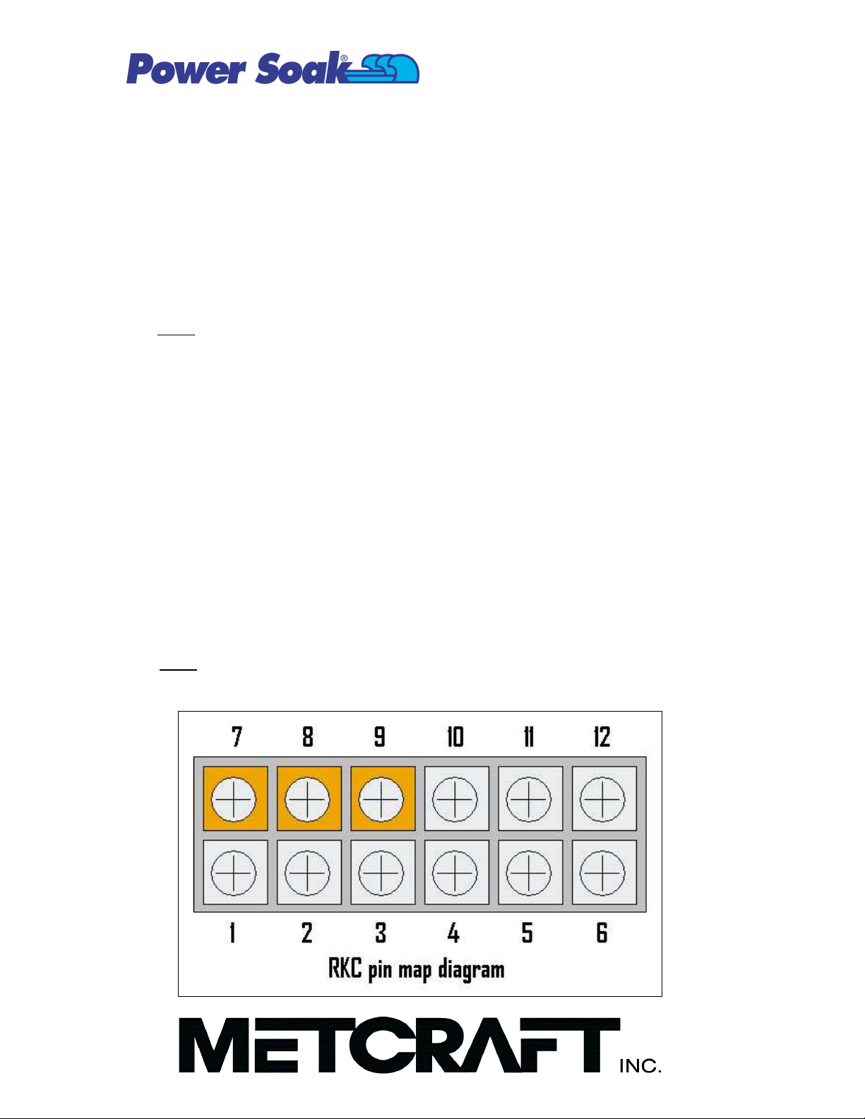
The RKC heat control pins are marked, but may be difficult to identify. The following
diagram maps the pin locations. Note the three gold pins as reference:
33
Page 35
Parts List
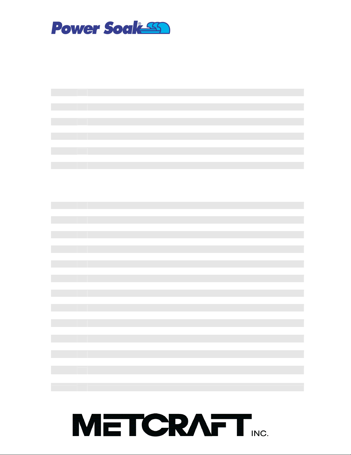
Pump Parts
29501
29507
26572
29743
21356
22446
25976
21884
25975
19345
24463
RS1011
Heater Parts
23985 GASKET-HEATER BOX ( SERIAL #’S 1000-1349 )
24181
24179
24849
24848
24847
28925
28926
21457
23727
CB1327
21203
18797
23983
23987
23988
24030 THERMOCOUPLE
19443
19296
23986 HEAT CONTROL
25757
25539
17263
17137
17127
CB1327
MOTOR-LEESON 2HP 230V
MOTOR-LEESON 2HP 208V
FAN-BALDOR MOTOR
PUMP WITH MOTOR, IMPELLER AND CASING GASKET (W/B 2HP)
FRAME ADAPTOR WITH WEAR RING
SHAFT SLEEVE
SNAP RING
IMPELLER
IMPELLER KEY
GASKET-PUMP CASING (W)
SEAL KIT-PUMP
PUMP CLEANOUT PLUG
HEATER BOX RIGHT HAND UNITS ( SERIAL #’S 1000-1349 )
HEATER BOX LEFT HAND UNITS ( SERIAL #’S 1000-1349 )
GASKET-HEATER BOX ( SERIAL #’S 1350 AND UP )
HEATER BOX RIGHT HAND UNITS ( SERIAL #’S 1350 AND UP )
HEATER BOX LEFT HAND UNITS ( SERIAL #’S 1350 AND UP )
MODIFIED HEATER BOX LEFT HAND UNITS ( SERIAL #’S 1350 AND UP )
MODIFIED HEATER BOX RIGHT HAND UNITS ( SERIAL #’S 1350 AND UP )
SWITCH OPERATOR-HEATER
SWITCH BLOCK-HEATER
CAP NUT (4)
VENT PLUG
TERMINAL BLOCK
DECAL-HEATER BOX
SENSOR PROBE
GASKET-SENSOR PROBE
GASKET-THERMOCOUPLE
QUENCH ARC
GUARD PLATE-HEAT CONTROL
BUTTON ASSEMBLY & BEZEL-HEAT CONTROL
SINK HEATER
GASKET-HEATER
STUD #10-24 X ¾” (4)
NUT CAP #10-24 RUBBER SEAL (4)
34
Page 36

052
Parts List - Continued
Control Panel Parts
23949
23894
23895
23896
23727
21458
29444
17394
24223
24224
19885
21473
21472
23579
23580
20281
20637
20280
29939
27833
SCREW-CONTROL PANEL (2)
GASKET-CONTROL PANEL
START SWITCH-PUSH BUTTON
STOP SWITCH-PUSH BUTTON
SWITCH BLOCK-STOP
SWITCH BLOCK-START ( SERIAL #S 1026 AND ABOVE )
SWITCH BLOCK-START ( SERIAL #S 1000-1025 )
CONTACTOR-PUMP
CONTACTOR-HEATER
TIMER
SOCKET, TIMER
LIQUID LEVEL CONTROL
SOCKET, LIQUID LEVEL CONTROL
HOLD DOWN CLIP, LIQUID LEVEL CONTROL (2)
FUSE BLOCK, MAIN
MOUNT-FUSE BLOCK
GROUDING BLOCK
FUSE BLOCK, CONTROL CIRCUIT
FUSE 1 BUSSMAN LP-CC-30 (2)
FUSE 3 BUSSMAN ABC 2
OVERLOAD
#10-24 THREADED STUD (6)
HEX NUT ¼” X 20 (6)
NUT SERT #10-24 (2)
103-
RS1471
103-020
103-014
Miscellaneous Parts
24724
24853
24860
24841
24936
100-343
35
INTAKE BAFFLE ( SERIAL #’S 1000-1349 )
INTAKE BAFFLE 28” ( SERIAL #’S 1350 AND UP )
INTAKE BAFFLE 25” ( SERIAL #’S 1350 AND UP )
INSIDE HEATER COVER (BEFORE 3/1/99 SLIDE ON-SLIDE OFF )
INSIDE HEATER COVER (AFTER 3/1/99 HINGED )
"O" RING - LEVER DRAIN
Page 37
Electrical Schematic
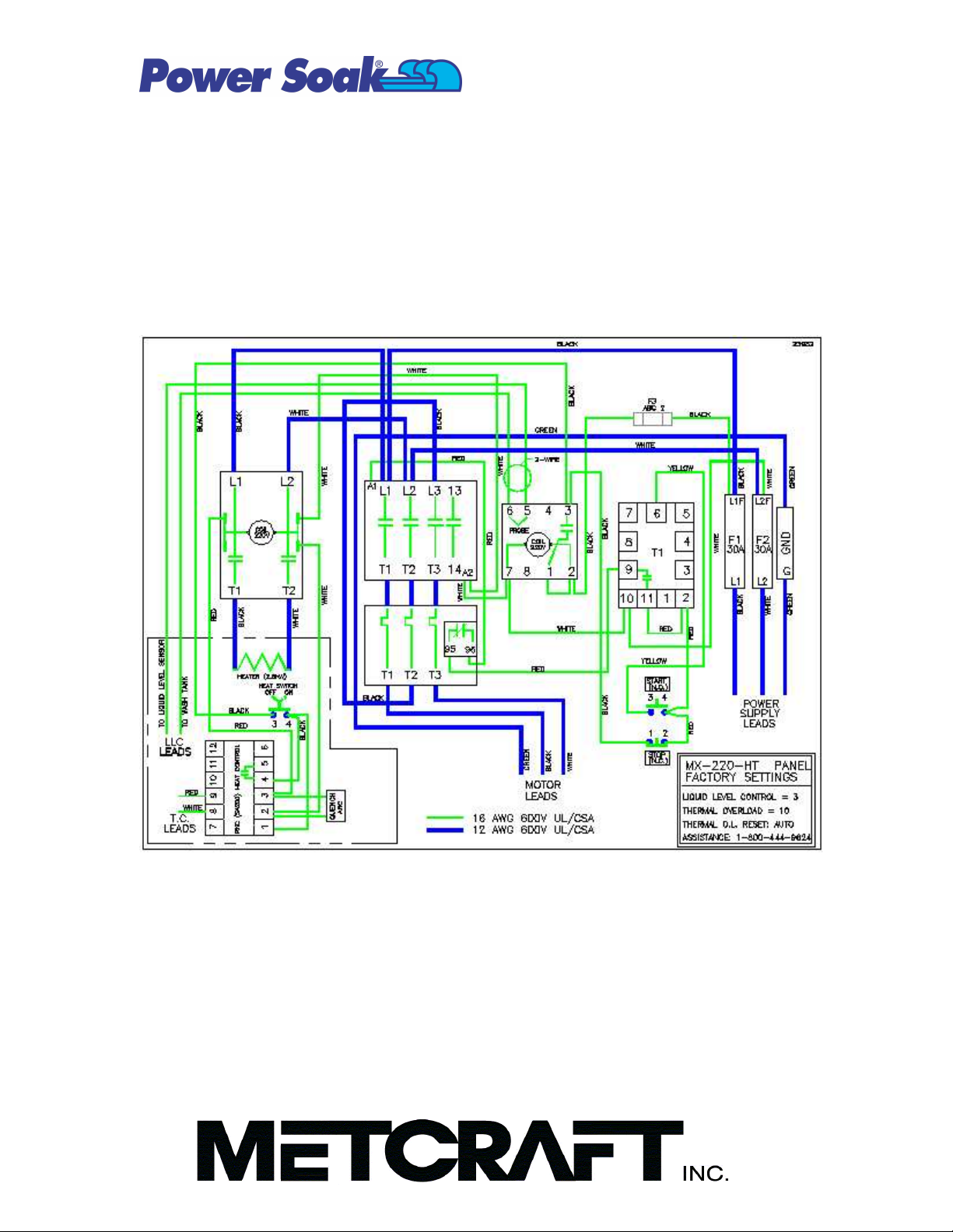
This schematic reflects the wiring for a RKC heat control, which replaces the Watlow heat
control.
36
Page 38
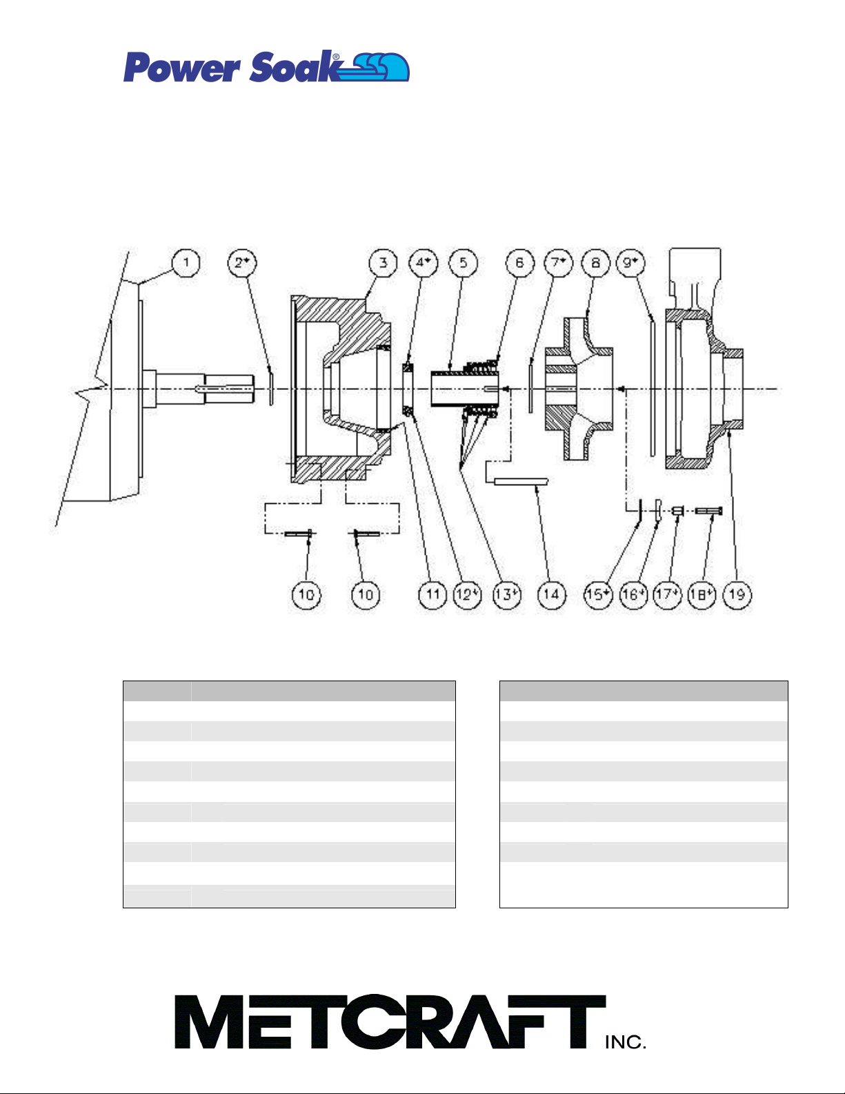
Motor and Pump Assembly
Exploded view
Item
1
2
3
4
5
6
7
8
9
10
* indicates parts included in the seal kit
Description
Motor, 2 HP, 50 Hz, 1 Ph, 230V 11
*
Sleeve O-ring 12
Black adapter with wear ring 13
*
Seat O-ring 14
Shaft sleeve 15
Retaining ring 16
*
Sleeve gasket 17
Impeller 18
*
Casing gasket 19
Screw
Item
Description
Adapter ring
*
Seal seat
*
Sleeve subassembly
Impeller key
*
Impeller washer gasket
*
Impeller washer
*
Impeller screw seal
*
Impeller screw
Casing
37
Page 39

Motor and Pump Assembly
Disassembly Procedure
1. Remove casing cap screws, which hold adapter to casing.
2. Pry adapter from casing with pry bar or large screwdriver and remove adapter and
motor from casing.
3. Using a suitable holder to keep impeller from turning, remove impeller cap screw
washer and gaskets. Be careful not to damage precision surfaces of impeller.
4. Remove impeller and impeller key from shaft.
5. With impeller and key removed, the shaft sleeve and the mechanical seal assembly can
be removed as a unit. Sometimes, the sleeve is difficult to remove due to rust from
moisture accumulation. If this is the case, applying heat to the sleeve exterior with a
torch and/or a gear puller may help. The heat allows the sleeve to expand. However,
too much heat may allow the shaft to expand as well.
6. Remove adapter cap screws, which hold adapter to motor.
7. Remove adapter from motor by prying with pry bar or screwdriver.
8. With adapter removed, the seal and seat ring can be pushed out with the fingers.
38
Page 40

Motor and Pump Assembly
Inspection and Repair of Components
With pump wet end disassembled, clean all parts and check for worn or damaged areas. It
is seldom economical on these pumps to repair damaged or worn parts. Therefore, when a
part is found unusable, it should be replaced.
Casing
Clean and inspect gasket surfaces for damaged areas that would cause leaks. Check
wearing ring surfaces for excessive wear.
Impeller
Check wearing ring surfaces for excess wear and gasket surfaces of impeller hub for
damage. If excessively worn or eroded, the impeller should be replaced.
Adapter
Clean and inspect gasket surfaces. Remove any dirt or scale from mechanical seal cavity.
Check adapter ring for wear and excess clearance.
Shaft Sleeve
Check for any damage to gasket surface on impeller end, O-ring groove on motor end, or
outside diameter where rubber bellow of mechanical seal contacts.
Mechanical Seal
It is not recommended that the mechanical seal be reused unless the pump has never been
run. A mechanical seal is like a gasket in this respect. Using an old one leaves too much
chance of failure to make the gamble worthwhile, considering the usual cost of installing
and removing a pump from it’s system.
Motor or Frame Shaft
Check the shaft for any bent condition by installing the shaft sleeve, clamping a dial
indicator to the motor face and reading runout at center of sleeve while turning shaft by
hand. Maximum allowable runout is .002 inches for proper performance of mechanical
39
Page 41

seal. Anything beyond this will require repairs to the motor, which are beyond the scope of
these instructions. Check motor fan and shroud for damage and clean, if necessary.
Motor and Pump Assembly
Assembly Procedure
The PowerSoak pumps are easy to put together. The hardest part, requiring the most care,
is installation of the mechanical seal parts.
Study the exploded diagram and become familiar with the name of each part. The diagram
shows the relative order of assembly, but also READ THE FOLLOWING
INSTRUCTIONS.
1. Make sure all of the parts are clean and ready for assembly. This means no dirt or
pieces of old gasket in the joints between the motor, adapter, and casing. Make sure the
parts around mechanical seal are clean. Dirt and misalignment will ruin a mechanical
seal.
2. Install the shaft sleeve o-ring in the place against the motor shaft shoulder. Don’t
let it be cut by the sharp edges of the keyway.
3. Push the mechanical seal seat squarely in the adapter. Use fingers only. A little
liquid soap (or light oil if soap not available) can be wiped on the outside of the seat
ring to make it slip easily into position. Don’t let it be cut by the edges of the adapter.
Don’t install the adapter on the motor face yet.
4. Check the shaft sleeve fit on the motor shaft. It should slide easily into place. If it
doesn’t, find out why. Do not try to drive the shaft sleeve onto the shaft with a
hammer. Check to make sure there are no score marks or scratches on the sleeve.
5. Install the adapter and tighten the cap screws, which hold tit to the motor face.
6. Remove any dirt particles and coat the lapped face of the mechanical seal with
clean SAE 10 or SAE 20 oil. DO NOT USE GREASE.
7. Slide the shaft sleeve on the shaft so that it covers the shaft sleeve o-ring and butts
against the shoulder.
8. Coat the shaft sleeve lightly with liquid soap (or light oil if soap not available).
40
Page 42

9. Carefully remove any particles from the lapped face of the carbon washer (part of
the mechanical seal) and coat it with clean SAE 10 or SAE 20 oil. DO NOT USE
GREASE.
41
Page 43

Motor and Pump Assembly
Assembly Procedure - Continued
10. Install the mechanical seal on the shaft sleeve by hand. A twisting motion may be
needed to make it ride smoothly over the shoulders on the sleeve. Push it by hand until
it contacts the seat, make sure the spring and spring holder line up properly. *(see note)
11. Install the snap ring using one hand to hold the snap ring pliers and the other hand to
compress the spring. When the spring pressure is released, the spring will push the
shaft sleeve outward, exposing the shaft sleeve o-ring to view temporarily.
12. Install the impeller key, first twisting the shaft sleeve on the shaft until the keyways
line up.
13. Install the shaft sleeve gasket.
14. Place the impeller on the shaft engaging the key.
15. Put the impeller screw gasket, impeller washer, and impeller washer gasket
together on the impeller screw as an assembly.
16. Install the impeller screw subassemblies. With one hand, push the impeller back
against the mechanical seal spring and with the other hand turn the impeller screw in
hand tight.
17. Check to see if the shaft sleeve has moved to its final position covering most of the
shaft sleeve o-ring.
18. Tighten the impeller screw to 15 ft-lb. torque.
19. Install the casing gasket on the shoulder of the adapter.
20. Install the casing and tighten all the casing screws.
21. Turn the motor shaft and check for any bindings or rubs caused by such things as
damaged or mis-aligned parts. Re-check all casing bolts for tightness. Tighten casing
bolts one at a time, turning the motor shaft, until rub disappears.
*NOTE
An optional procedure for assembly of the mechanical seal consists of mounting the
mechanical seal and the snap ring on the sleeve as a subassembly, which is then
placed in position on the motor shaft. Experienced pump mechanics may find that
this is more convenient as long as they recognize that this way introduces some
additional hazards of damaging or improper assembly of precision seal parts.
42
Page 44

43
Page 45
Installation Guide
The installation and initial operational check of your new system
must be performed only by licensed and certified plumbers and
electricians.
Be sure to follow all applicable national and local electrical codes
when installing the electrical supply and/or a new breaker. DO NOT
connect the system using a power cord and plug or an extension cord
of any kind.
Please refer to the detailed installation instructions that were sent with your Power Soak
system.
Providing Proper Electrical Service
The requirements of your new system are on the serial number plate located on the front of
the wash sink, adjacent to the control panel enclosure and inside the enclosure itself.
All PowerSoak systems have a single point electrical connection, and a dedicated circuit is
required.
44
Page 46

Providing Proper Electrical Service
The system is completely pre-wired and tested at the factory, and a hard-wired connection
from an appropriate power source junction box is all that is required.
The installer is to provide a disconnect that should be incorporated in the fixed wiring.
Properly sized watertight conduit, fittings and parts are required, as well as the appropriate
gauge wire.
If your system is a “left-to-right” unit, you should locate the power source junction box at
the left end of the system. (The opposite would be true for a “right-to-left” system.)
Ideally, the junction box should be located on the wall directly behind the pump motor and
control panel.
A wiring diagram is located in the system’s control panel enclosure. Specific part numbers
and part information can be obtained from the factory by calling 800-444-9624.
Plumbing Requirements
Your unit requires the following plumbing connections:
• 3/4” (19mm) or 1/2” (12 mm) hot and cold water supply lines.
• One wastewater connection (minimum 1 1/2” / 38mm).
45
Page 47

Notes
______________________________________________
______________________________________________
______________________________________________
______________________________________________
______________________________________________
______________________________________________
______________________________________________
______________________________________________
______________________________________________
______________________________________________
______________________________________________
______________________________________________
______________________________________________
______________________________________________
______________________________________________
______________________________________________
______________________________________________
______________________________________________
______________________________________________
______________________________________________
______________________________________________
______________________________________________
______________________________________________
______________________________________________
______________________________________________
46
Page 48

______________________________________________
47
Page 49

Notes
______________________________________________
______________________________________________
______________________________________________
______________________________________________
______________________________________________
______________________________________________
______________________________________________
______________________________________________
______________________________________________
______________________________________________
______________________________________________
______________________________________________
______________________________________________
______________________________________________
______________________________________________
______________________________________________
______________________________________________
______________________________________________
______________________________________________
______________________________________________
______________________________________________
______________________________________________
______________________________________________
______________________________________________
______________________________________________
______________________________________________
48
Page 50

Power Soak is a registered trademark of Cantrell Industries, Inc.
The Power Soak design and concept is fully patented.
13910 Kessler Drive, Grandview, MO 64030
Phone: (816) 761-3250 Fax: (816) 761-0544
(800) 444-9624
www.powersoak.com
49
 Loading...