

Page 1
INSTRUCTION MANUAL
7500W Portable Generator
Model # PS48
Have product questions or need technical support? Please feel free to contact us!
Website: www.Amerisuninc.com
Toll free: 1-800-791-9458 Mon-Fri 9-5 EST
Email: support@amerisuninc.com
Page 2

2
Page 3

CONTENTS
Technical data…...………………………………………………………... 3
Introduction………………………………………………………………. 4
Safety information…….………………………………………………... 4
General safety procedures ……....……………………………………… 5
Important safety instructions……………………………………………. 6
Knowing your generator………………………………………………… 7
Generator preparation…………………………………………………... 8
Step 1 Setup wheel kit…………………………………………. 8
Step 2 Add oil…………………………………………………… 8
Step 3 Add gasoline……………………………………………… 9
Step 4 Ground the generator……………………………………. 10
Step 5 Connect the battery…………………………………… 10
Starting the generator………....………………………………………… 11
Stopping the generator…………………………………………………. 13
Using the generator……………………………………………………... 13
Maintenance……………………………………………………………... 15
Storage & transport procedures…………………………………………. 20
Troubleshooting…………………………………………………………. 20
Wiring diagram…………………………………………………………. 21
Exploded view & parts list……………………………………………… 22
Warranty………………………………………………………………… 26
TECHNICAL DATA
7500W Generator Model # PS48
Engine type: 4 stroke, OHV, single cylinder with forced air cooling system
Spark plug: F6TC
Spark plug gap: 0.7-0.8 mm (0.028-0.031 in)
Spark plug torque: 1/2-3/4 turn after gasket contacts base or 15 ft.lb
Displacement: 420 cc
Fuel tank capacity: 7.4 gallons / 87 octane minimum
Oil capacity: 37 fl.oz
Lubrication system: Splash lubrication
Rated wattage: 7000W
Surge wattage: 7500W
Rated voltage: 120V/ 240V
Rated amperage: 58.3A/29.2A
Frequency: 60Hz
Phase: Single
Battery: 12VDC, 14Ah
Dimensions (L x W x H): 29.1x21.9x24.4 inches
Run time on 50% load: 9.5 hours
Noise rating: 78 dB at 23 feet
Weight: 206 lb.
3
Page 4

4
INTRODUCTION
Thank You for Purchasing a PowerSmart® Product. This manual provides information regarding the safe
operation and maintenance of this product. Every effort has been made to ensure the accuracy of the
information in this manual. PowerSmart® reserves the right to change this product and specifications at
any time without prior notice.
Please keep this manual available to all users during the entire life of the generator.
This manual contains special messages to bring attention to potential safety concerns,
generator damage as well as helpful operating and servicing information. Please read all the
information carefully to avoid injury and machine damage.
QUESTIONS? PROBLEMS?
In order to answer questions and solve problems in the most efficient and speedy manner, contact
Customer Service at (800) 791-9458, Mon-Fri 9am-5pm EST or email: support@amerisuninc.com.
NOTICE REGARDING EMISSIONS
Engines that are certified to comply with U.S. EPA emission regulations for SORE (Small Off Road
Equipment), are certified to operate on regular unleaded gasoline, and may include the following
emission control systems: (EM) Engine Modifications and (TWC) Three-Way Catalyst (if so equipped).
SAFETY INFORMATION
Before operating this generator, read and observe all warnings, cautions, and instructions on the
generator and in this Owner’s Manual.
NOTE: The following safety information is not meant to cover all possible conditions and situations that
may occur. Read the entire Owner’s Manual for safety and operating instructions. Failure to follow
instructions and safety information could result in serious injury or death.
This safety alert symbol is used to identify safety information about hazards that can result in personal
injury.
A signal word (DANGER, WARNING, or CAUTION) is used with the alert symbol to
indicate the likelihood and the potential severity of injury. In addition, a hazard symbol may
be used to represent the type of hazard.
DANGER indicates a hazard, which, if not avoided, will result in death or serious injury.
WARNING indicates a hazard, which, if not avoided, could result in death or serious injury.
CAUTION indicates a hazard, which, if not avoided, might result in minor or moderate injury.
CAUTION when used without the alert symbol, indicates a situation that could result in damage to the
engine or generator.
Page 5
5
GENERAL SAFETY PROCEDURES
For any questions regarding the hazard and safety notices listed in this manual or on the product, please
call (800) 791-9458 Mon-Fri 9-5 EST before using the generator.
DANGER: CARBON MONOXIDE
Using a generator indoors CAN KILL YOU IN MINUTES. Generator exhaust contains carbon monoxide
(CO). This is a poison gas you cannot see or smell. If you can smell the generator exhaust, you are
breathing CO. But even if you cannot smell the exhaust, you could be breathing CO.
NEVER use a generator inside homes, garages, crawlspaces, or other partly enclosed areas. Deadly levels
of carbon monoxide can build up in these areas. Using a fan or opening windows and doors does NOT
supply enough fresh air. ONLY use a generator outside and far away from windows, doors, and vents.
These openings can pull in generator exhaust.
Even if you use a generator correctly, CO may leak into the home. ALWAYS use a battery-powered or
battery-backup CO alarm in the home. If you start to feel sick, dizzy, or weak after the generator has been
running, move to fresh air RIGHT AWAY. See a doctor. You may have carbon monoxide poisoning.
WARNING: The exhaust from this product contains chemicals known to the State of
California to cause cancer, birth defects, or other reproductive harm.
WARNING: This generator may emit highly flammable and explosive gasoline vapors,
which can cause severe burns or even death if ignited. A nearby open flame can lead to
explosion even if it isn’t directly in contact with gasoline.
• Do not operate near open flame.
• Do not smoke near generator.
• Always operate on a firm, level surface.
• Always turn generator off before refueling. Allow generator to cool for at least 2 minutes before
removing fuel cap. Loosen cap slowly to relieve pressure in tank.
• Do not overfill fuel tank. Gasoline may expand during operation. Do not fill to the top of the tank.
Allow for expansion.
• Always check for spilled fuel before operating.
• Empty fuel tank before storing or transporting the generator.
WARNING: This generator produces powerful voltage, which can result in electrocution.
• ALWAYS ground the generator before using it (see the “Ground the Generator” portion of the
“GENERATOR PREPARATION” section).
• Generator should only be plugged into electrical devices, either directly or with an extension
cord.
NEVER connect to a building electrical system without a qualified electrician. Such connections must
comply with local electrical laws and codes. Failure to comply can create a back-feed, which may result
in serious injury or death to utility workers.
• Use a ground fault circuit interrupter (GFCI) in highly conductive areas such as metal decking or
steel work. GFCIs are available in-line with some extension cords.
• Do not use in rainy conditions.
• Do not touch bare wires or receptacles (outlets).
• Do not allow children or non-qualified persons to operate.
Page 6

6
WARNING: This generator produces heat when running. Temperatures near exhaust can
exceed 1500F (650 C).
Do not touch hot surfaces. Pay attention to warning labels on the generator identifying hot parts of the
machine.
Allow generator to cool down after use before touching engine or areas of the generator that become hot
during use.
CAUTION: Misuse of this generator can damage it or shorten its life.
Only use generator for its intended purposes.
Operate only on dry, level surfaces.
Allow generator to run for several minutes before connecting electrical devices.
Shut off and disconnect any malfunctioning devices from generator.
Do not exceed the wattage capacity of the generator by plugging in more electrical devices than the unit
can handle.
Do not turn on electrical devices until after they are connected to the generator.
Turn off all connected electrical devices before stopping the generator.
Turn the engine switch to “OFF” position when the engine is not running.
IMPORTANT SAFETY INSTRUCTIONS
SAVE THESE INSTRUCTIONS – This manual contains important instructions for the PowerSmart®
3500W generator that should be followed during installation and maintenance of the generator.
Generators vibrate in normal use. During and after the use of the generator, inspect both the generator as
well as extension and power supply cords for damage resulting from vibration. Have damaged items
repaired or replaced as necessary. Do not use plugs or cords that show signs of damage such as broken or
cracked insulation.
For power outages, permanently installed stationary generators are better suited for providing backup
power to the home. Even a properly connected portable generator can become overloaded. This may
result in overheating or stressing of the components, possibly leading to a generator failure.
WARNING: If this generator is used as a supply for a building’s wiring system, the generator
must be installed by a qualified electrician and connected to a transfer switch as a separately
derived system in accordance with the National Electrical Code, NFPA 70. The generator
shall be connected to a transfer switch that switches all conductors excluding the equipment grounding
conductor. The frame of the generator shall be connected to an approved grounding electrode.
Page 7
7
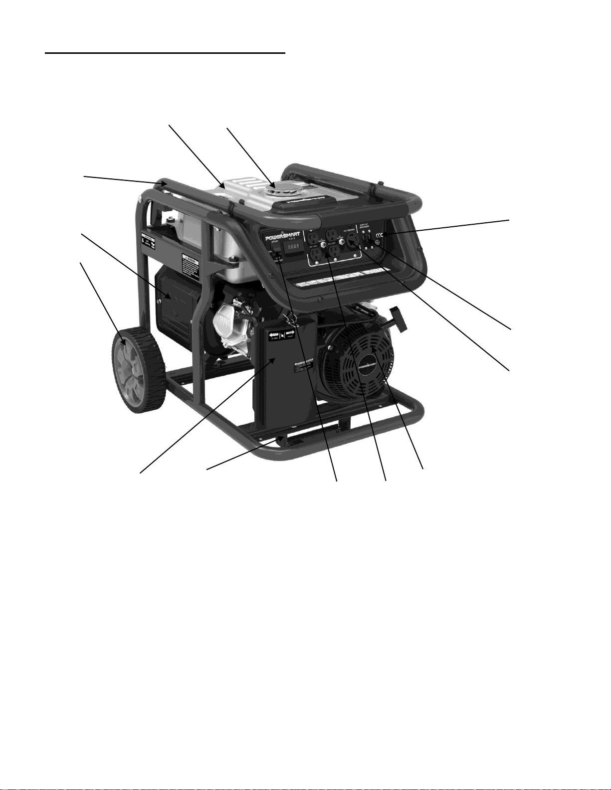
KNOWING YOUR GENERATOR
Use the illustrations below to become familiar with the locations and functions of the various components
and controls of this generator.
1 Handle
8
Recoil starter
2 Muffler
9
30A 120V/240V Receptacle
3 Wheel
10 Circuit breaker
4 Air cleaner
11 Grounding nut
5 Front foot
12 Fuel tank cap
6 Engine switch
13 Fuel tank
7 20A Duplex Receptacle
13 12
1
2
3
11
10
9
4 5 6 7 8
Page 8
8
PREPARATION
The following section describes steps necessary to prepare the generator for use. If after reading this
section, you are unsure about how to perform any of the steps please call (800) 791-9458 Mon-Fri 9-5
EST for customer service. Failure to perform these steps properly can damage the generator or shorten its
life.
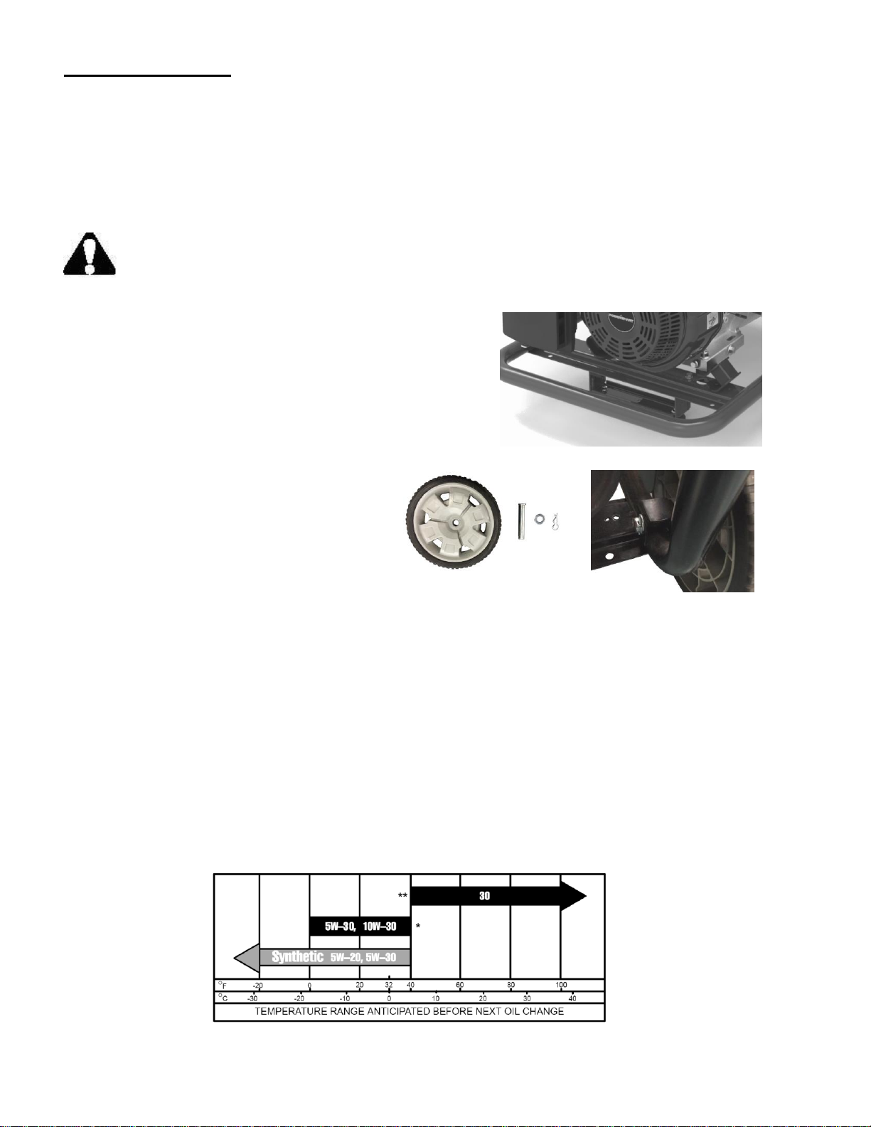
Step 1 - SETUP WHEEL KIT
WARNING: This generator is heavy. Assembly procedures may require lifting equipment or
two people.
ATTACH FRONT FOOT
To attach the feet to the generator, perform the following
steps:
1. Find a wooden block or a similarly sturdy item that is at
least three inches thick. Stack the end of the generator
with the recoil starter onto the wooden block.
2. Setup front foot as attached picture.
ATTACH WHEELS
To attach the wheels to the generator, perform
the following steps:
1. Rest the exhaust end of the generator on
the same wooden block used for attaching
the front foot.
2. Slide the wheel onto the axle.
3. Slide the wheel shaft with the cotter pin hole inward through the frame.
Secure using the cotter pin.
4. Repeat steps 2 and 3 for the other wheel.
Step 2 - ADD OIL
The generator is shipped without oil. User must add the proper amount of oil before operating the
generator for the first time. The oil capacity of the engine crankcase is 37 fl. oz. For general use (above
40° F), we recommend 30W, 4-stroke engine oil.
ENGINE OIL RECOMMENDATIONS
Select good quality detergent oil bearing the American Petroleum Institute (API) service classifications
SJ, SL, or SM (synthetic oils may be used). Use the ASE viscosity grade of oil from the following chart
that matches the starting temperature anticipated before the next oil changes.
Engine Oil Temperature Recommendations
Page 9
9
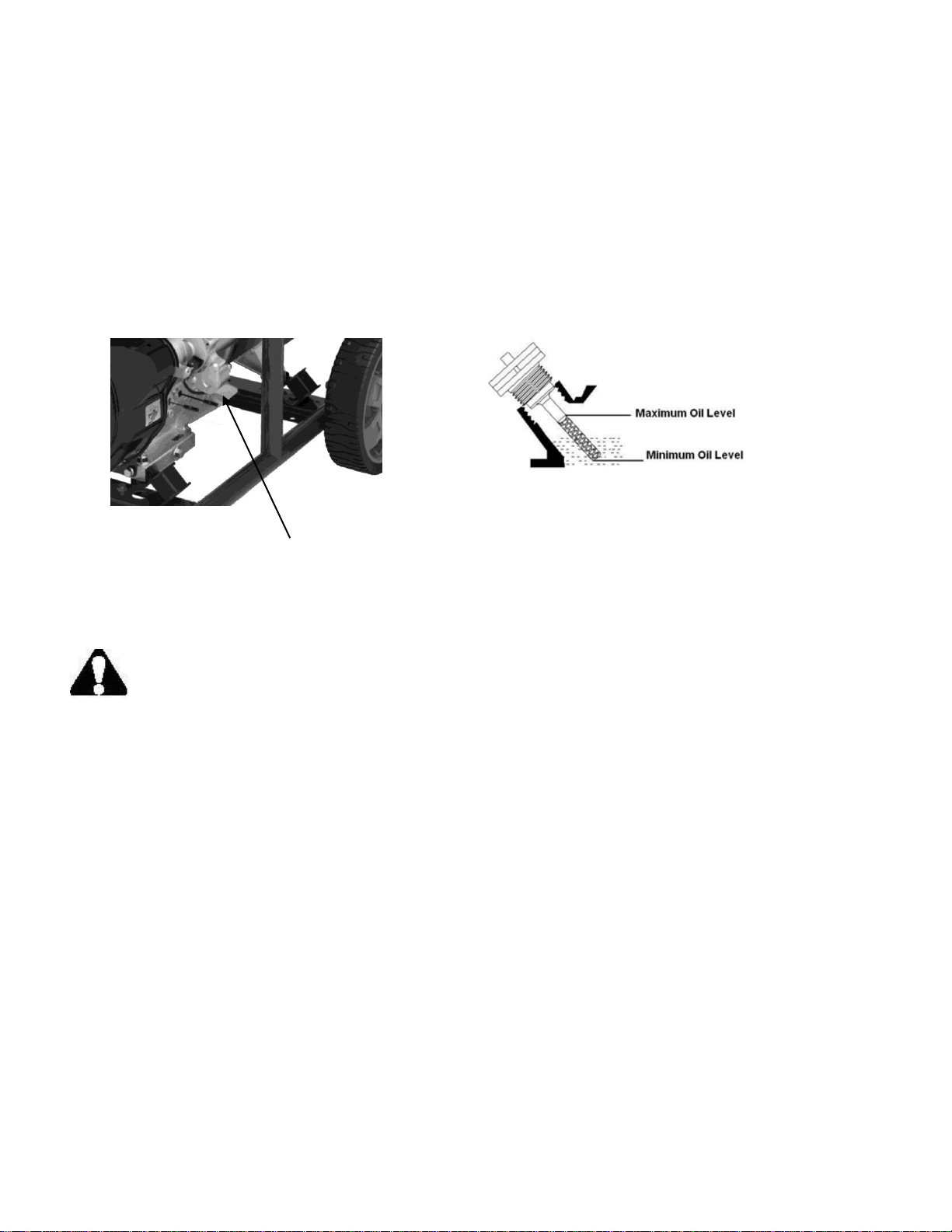
To add oil, follow these steps:
1. Make sure the generator is on a level surface. Tilting the generator to assist in filling will cause oil to
flow into engine areas and will cause damage. Keep generator level!
2. Remove the dipstick from the engine.
3. Add oil slowly as to not overflow the unit.
4. To check the oil level, wipe the dipstick with a clean rag. Insert the dipstick into the oil fill opening
without screwing it in. Remove the dipstick to check the oil mark.
5. Slowly add more oil and repeat step 4 until the oil mark reaches to the top of the dipstick. Do not
overfill the crankcase. The generator is equipped with a low-oil sensor and will not start if the amount
of oil is insufficient.
6. Check for oil leaks. Tighten dipstick firmly.
Step 3 - ADD GASOLINE
WARNING: This generator may emit highly flammable and explosive gasoline vapors,
which can cause severe burns or even death if ignited. A nearby open flame can lead to
explosion even if not directly in contact with gasoline.
Use fresh (within 30 days from purchase), lead-free gasoline with a minimum of 87 octane rating. Do not
mix oil with gasoline.
To add gasoline, follow these steps:
1. Make sure the generator is on a level surface.
2. Unscrew fuel cap and set aside. NOTE: The fuel cap may be tight and hard to unscrew.
3. Slowly add unleaded gasoline to the fuel tank. Be careful not to overfill. The capacity of the fuel tank
is 7.4 gallons. NOTE: Do not fill the fuel tank to the very top. Gasoline will expand and spill over
during use even with the fuel cap in place.
4. Reinstall fuel cap and wipe clean any spilled gasoline with a dry cloth.
IMPORTANT:
• Never use an oil/gasoline mixture.
• Never use old gasoline.
• Avoid getting dirt or water into the fuel tank.
• Gasoline can age in the tank and make starting difficult. Never store generator for extended
periods of time with fuel in the tank or the carburetor.
• Turn the fuel cock off and drain the fuel from the carburetor.
Oil Dipstick
Page 10

10
Step 4 - GROUND THE GENERATOR
WARNING: Failure to properly ground the generator can
result in electrocution.
Ground the generator by tightening the grounding nut on the
front control panel against a grounding wire. A generally acceptable
grounding wire is a No. 12 AWG (American Wire Gauge) stranded
copper wire. This grounding wire should be connected at the other end
to a copper, brass, or steel-grounding rod that is driven into the earth.
Wire and grounding rods are not included in generator contents.
Grounding codes can vary by location. Contact a local electrician to
check the area codes.
Step 5 – CONNECT THE BATTERY
WARNING: Battery gives off explosive hydrogen gas.
Keep battery away from spark, flame, or cigarette.
Do not connect or disconnect battery while generator is running.
Service or use battery only in well ventilated areas.
WARNING: Battery contains sulfuric acid. Battery acid is poisonous. Tilting the generator
with the battery installed can cause battery acid to spill.
Wear protective clothing and eyewear when servicing battery.
Keep out of reach of children.
Do not tilt generator with battery installed.
If battery acid gets on your skin, wash with water immediately.
If battery acid gets in your eyes, flush with water for at least 15 minutes and call a doctor immediately.
If battery acid is swallowed, drink a large amount of water or milk. Then drink milk of magnesia or
vegetable oil. Call a doctor immediately.
The generator comes with the battery disconnected for safety. To use the electric start, the battery needs
to be connected. To connect the battery:
1. Remove the protective covering from the free end of the negative battery cable. This cable is
connected to the generator on the other end and is located in the vicinity of the battery.
2. Attach the free end of the negative cable to the battery and secure the connection.
NOTE: If you do not plan to use the generator for a long period of time, it is a good idea to disconnect the
negative battery cable from the battery for storage. After disconnecting the cable, cover the free end with
an insulator such as electrical tape.
NOTE: After completing the above preparation, the generator is ready to be started.
Grounding Nut
Page 11

11
STARTING THE GENERATOR
Before starting the generator, make sure you have read and performed the steps in the “Generator
Preparation” section of this manual. If you are unsure about how to perform any of the steps in this
manual, please call (800) 791-9458 Mon-Fri 9-5 EST for customer service.
DANGER: CARBON MONOXIDE.
Using a generator indoors CAN KILL YOU IN MINUTES.
Generator exhaust contains carbon monoxide (CO). This is a poison gas you cannot see or smell. If you
can smell the generator exhaust, you are breathing CO. Even if you cannot smell the exhaust, you may be
breathing CO.
NEVER use a generator inside homes, garages, crawlspaces, or other partly enclosed areas. Deadly
levels of carbon monoxide can build up in these areas. Using a fan or opening windows and doors does
NOT supply enough fresh air.
ONLY use a generator outside and far away from windows, doors, and vents. These openings can pull in
generator exhaust. Even if you use a generator correctly, CO may leak into the home. ALWAYS use a
battery-powered or battery-backup CO alarm in the home.
If you start to feel sick, dizzy, or weak after the generator has been running, move to fresh air RIGHT
AWAY. See a doctor. You may have carbon monoxide poisoning.
WARNING: This generator produces powerful voltage, which can result in electrocution.
ALWAYS ground the generator before using it (see the “Ground the Generator” portion of the
“Generator Preparation” section).
• Generator should only be plugged into electrical devices, either directly or with an extension cord.
NEVER connect to a building electrical system without a qualified electrician. Such connections
must comply with local electrical laws and codes. Failure to comply can create a back-feed, which
may result in serious injury or death to utility workers.
• Use a ground fault circuit interrupter (GFCI) in highly conductive areas such as metal decking or steel
work. GFCIs are available in-line with some extension cords.
• Do not use in rainy or wet conditions.
• Do not touch bare wires or receptacles (outlets).
• Do not allow children or non-qualified persons to operate.
CAUTION: Disconnect all electrical loads from the generator before attempting to start.
Page 12

12
MANUAL START THE ENGINE
To manual start the generator, perform the following steps:
1. Unplug all electrical devices from the generator during ignition. Otherwise
it will be difficult for the engine to start.
2. Check that the generator is properly grounded (Refer to “GROUND THE
GENERATOR”).
3. Check the oil and fuel levels.
4. Turn the fuel valve to the “ON” position.
5. Move the choke lever to the “CLOSE” position.
6. Set the ON/OFF Switch to the “ON” position.
7. Pull on the recoil starter handle slowly until a slight
resistance is felt, then pull quickly to start the engine.
Return cord gently into the recoil starter. Never allow the
cord to snap back.
8. If engine fails to start, repeat step 7. NOTE: After
repeated failed attempts to start the engine, please consult
the troubleshooting guide before attempting again. If problems
persist, please call (800) 791-9458 M-F 9am-5pm EST.
9. Once the engine has started, slowly return the choke lever all the
way to the “OPEN” position.
10. Allow the engine to run for several minutes before attempting to
connect any electrical devices. This allows the generator to
stabilize its speed and temperature.
ELECTRIC START THE ENGINE
To start the generator using the electric start function, perform the following steps:
1. Make sure no electrical devices are connected to the generator. Such devices can make it difficult for
the engine to start.
2. Check that the generator is properly grounded (Refer to “Ground the Generator”).
3. Check the oil and gas levels.
4. Turn the fuel valve to the “ON” position.
5. Move the choke lever to the “Start” position.
6. Set the engine switch to the “ON” position.
7. Press the engine switch to the “START” position for 2-3 seconds or until the engine starts. NOTE: If
the engine does not start after 2-3 seconds, release the switch from the start position. Keeping the
switch in the START position too long can damage the starter.
8. If engine fails to start, wait 10 seconds, then repeat step 7. NOTE: After repeated attempts to start the
engine, please consult the troubleshooting guide before attempting again. If problems persist please
call (800) 791-9458 Mon-Fri 9-5 EST.
9. Once the engine has started. Slowly move the choke lever all the way to the “Run” position. Allow
the generator to run for several minutes before attempting to connect any electrical devices.
Engine Switch
Page 13

13
STOPPING THE GENERATOR
TO STOP THE GENERATOR
1. Turn off all electrical devices prior to unplugging them from the generator. Unplugging running
devices can cause damage to the generator.
2. Turn the “ON/OFF” switch to the “OFF” position.
3. Turn the fuel valve to the “OFF” (horizontal) position.
WARNING: Allow the generator to cool for several minutes before touching areas that
become hot during use.
CAUTION: Allowing gasoline to sit in the fuel tank for long periods of time can make it difficult to start
the generator in the future. Never store the generator for extended periods of time with fuel in the fuel
tank. Refer to Generator Storage Section.
USING THE GENERATOR
WARNING: When this generator is used on a building’s wiring system, the generator must be installed
by a qualified electrician and connected to a transfer switch as a separately derived system in accordance
with the National Electrical Code, NFPA 70. The generator shall be connected to a transfer switch that
switches all conductors other than the equipment grounding conductor. The frame of the generator shall
be connected to an approved grounding electrode.
For power outages, permanently installed stationary generators are better suited for providing backup
power to the home. Even a properly connected portable generator can become overloaded. This may
result in overheating or stressing the machine’s components, possibly leading to a generator failure.
Before connecting electrical devices, allow the generator to run for a few minutes to stabilize the speed
and voltage output.
CAUTION: Become familiar with the markings on the panel before connecting electrical devices.
Connect electrical devices running on AC current according to their wattage requirements. The chart
below shows the rated and surge wattage of the generator.
Model
Rated Wattage
Surge Wattage
PS48
7000W
7500W
The rated (running) wattage is the wattage the generator can produce on a continuous basis.
The surge wattage is the maximum amount of power the generator can produce for an extremely short
period of time (seconds). Many electrical devices such as refrigerators require short bursts of extra power
in addition to the rated wattage listed by the device to start their motors. The surge wattage ability of the
generator covers this extra power requirement.
The total running wattage requirement of the electrical devices connected to the generator should not
exceed the rated wattage of the generator itself. To calculate the total wattage requirement of the
electrical devices you plan to connect, find the rated (or running) wattage of each device. This number
Page 14

14
should be listed somewhere on the device or in its instruction manual. If this wattage cannot be found,
calculate it by multiplying the Voltage requirement by the Amperage drawn:
Watts = Volts x Amperes
If these specifications are not available, estimate the wattages requirement of the device by using the
chart in next page.
When the rated wattage requirement of each electrical device has been determined, add these numbers to
find the total rated wattage needed. If this number exceeds the rated wattage of the generator, DO NOT
connect all these devices. Select a combination of electrical devices, which have a total rated wattage
lower than or equal to the rated wattage of the generator.
CAUTION: The generator can run at its surge wattage capacity for only a short time. Connect electrical
devices requiring a rated (running) wattage equal to or less than the rated wattage of the generator. Never
connect devices requiring a rated wattage equal to the surge wattage of the generator. This can trip the
circuit protectors (circuit breakers).
Tool or appliance
Rated watts
Additional surge watts
Electric water heater (40 Gal)
4000
0
Hot plate
2500
0
Radial arm saw
2000
2000
Electric stove (each element)
1500-2800
0
Circular saw
1500
1500
Air compressor (1 HP)
1500
3000
Window air conditioner
1200
1800
Miter saw
1200
1200
Microwave
1000
0
Well water pump
1000
1000
Reciprocating saw
960
1040
Sump pump
800
1200
Refrigerator freezer
800
1200
Furnace blower
800
1300
Computer
800
0
Electric drill
600
900
Television
500
0
Deep freezer
500
500
Garage door opener
480
0
Stereo
400
0
Box fan
300
600
Clock radio
300
0
Security system
180
0
DVD player
100
0
Common light bulb
75
0
Estimated wattage requirements of common electrical devices
Note: The above wattage figures are estimates. Check the wattage listed on the electrical device before
consulting this chart. Once the electrical devices that will be powered by the generator have been
determined, connect these devices.
CAUTION: Do not connect 50Hz loads to the generator.
Page 15

15
SOME NOTES ABOUT POWER CORDS
Long or thin cords can drain the power provided to an electrical device by the generator. When using
such cords, allow for a slightly higher rated wattage requirement by the electrical device. See below for
recommended cords based on the power requirement of the electrical device.
Ampere Rating
Total Length of Cord in feet
More Than
Not More Than
25
50
100
150 0 6
18
16
16
14 6 10
18
16
14
12
10
12
16
16
14
12
12
16
14
12
Not Recommended
Maximum extension cord lengths by power requirement
If an overload occurs, shut down the generator. Unplug all electrical devices and wait five minutes. Then,
start the unit back up again to get power back.
MAINTENANCE
Proper routine maintenance of the generator will help prolong the life of the machine. Please perform
maintenance checks and operations according to the schedule in below chart.
Recommended
maintenance schedule
Each 8
hours or
daily
First 8
hours
Every 25
hours
Every 3
months or
50 hours
Every 6
months or
100 hours
Every
year
As
necessary
Engine
oil
Check
lever
x
Replace
x x*
x*
Air
cleaner
Check x x
Clean x
Spark
plug
Check
/Clean
x
Change
x x
Fuel tank
Check
lever
x
*Clean/change more often under dusty conditions or operating under heavy load.
Recommended maintenance schedule
CLEANING THE GENERATOR
Never clean the generator when it is running! Never clean with a bucket of water or a hose. Water can get
inside the working parts of the generator and cause a short circuit or corrosion.
Always try to use the generator in a cool, dry place. If the generator becomes dirty, clean the exterior with
a damp cloth, a soft brush, a vacuum or pressurized air.
CHECKING THE OIL
The oil capacity of the engine crankcase is 37 fl. oz.
Page 16
16
Check the oil level of the generator according to the Recommended Maintenance Schedule above. The
generator is equipped with an automatic shutoff to protect it from running on low oil. This is a critical
step for proper engine starting. To check the oil level:
1. Make sure the generator is on a level surface.
2. Clean around oil fill. Remove dipstick and wipe the
dipstick with a clean rag. Insert the dipstick into the oil
fill opening without screwing in. Remove the dipstick to
check the oil mark. Add oil if the oil mark covers less
than one half of the dipstick.
3. Slowly add more oil and repeat step 2 until the oil mark
reaches to the top of dipstick. Do not over fill the
crankcase.
4. Reinstall oil dipstick.
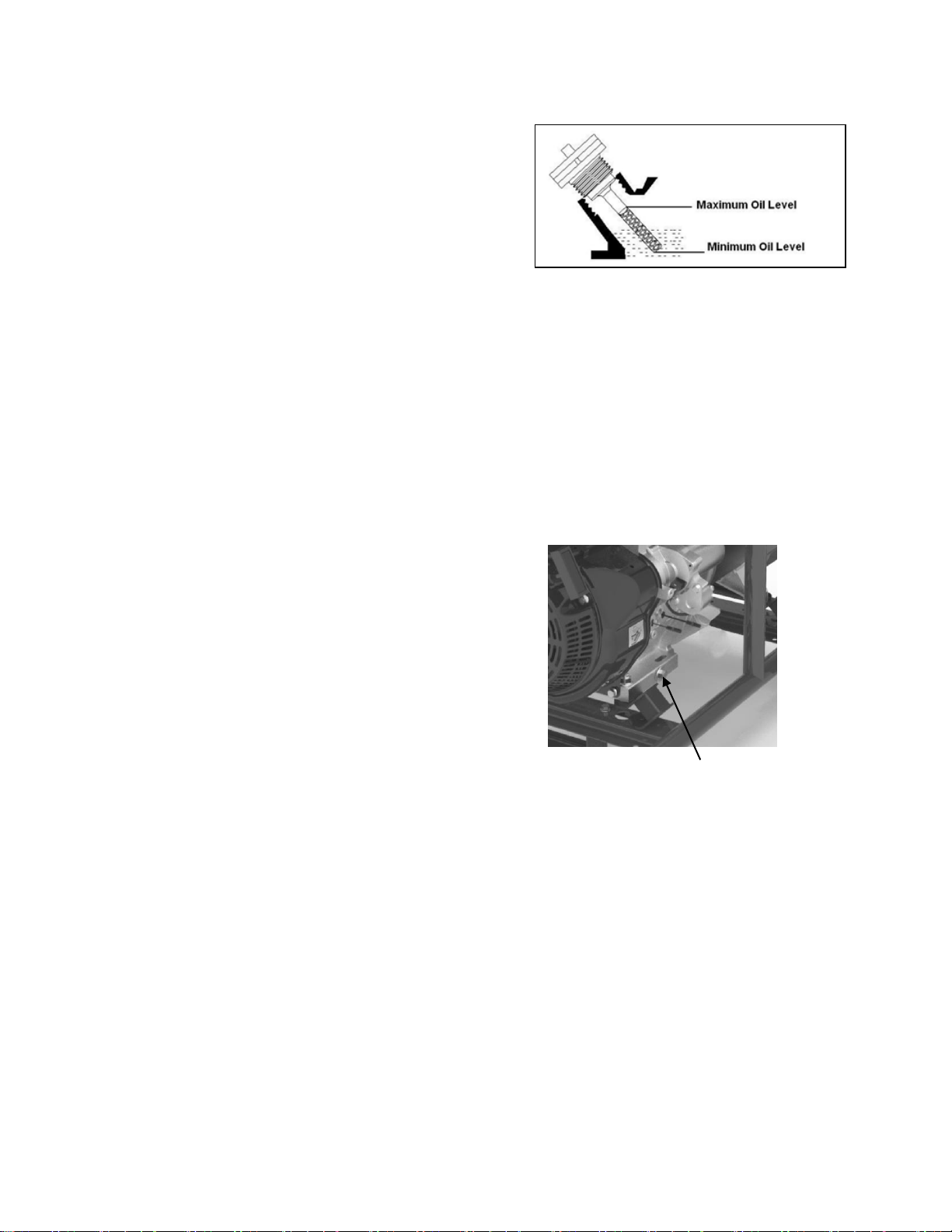
CHANGING/ADDING OIL
Change the oil according to the Recommended Maintenance Schedule. Change the oil when the engine is
warm. This will allow for complete drainage. Change oil more often if operating under heavy load or high
ambient temperatures. It is also necessary to drain the oil from the crankcase if it has become
contaminated with water or dirt. The oil capacity of the generator engine is 37 fl.oz. Add oil when the oil
level is low. For proper type and weight of oil refer to “add oil” portion of the “Generator Preparation”
section.
To drain oil, follow these steps:
1. Place a container underneath the engine to catch oil as it
drains.
2. Using a wrench, unscrew the oil drain bolt. Allow all the
oil to drain from the engine.
3. Reinstall the oil drain bolt and tighten with a wrench.
To refill the crankcase with oil, follow these steps:
1. Make sure the generator is on a level surface. Tilting the generator to assist in filling will cause oil to
flow into engine areas and will cause damage. Keep generator level!
2. Remove the dipstick from the engine.
3. Using a funnel or appropriate dispenser, add the correct amount of oil (37 fl.oz) into the crankcase.
The engine is equipped with a low oil sensor and will not start if the amount of oil is insufficient.
4. Reinstall dipstick.
NOTE: Never dispose of used motor oil in the trash or down a drain. Please call a local recycling center
or auto garage to arrange oil disposal.
AIR CLEANER MAINTENANCE
Routine maintenance of the air cleaner helps maintain proper airflow to the carburetor. Occasionally
check that the air cleaner is free of excessive dirt. Refer to Recommended Maintenance Schedule page
15. For air cleaner detail:
1. Unhinge the clasps at the top and bottom of the air cleaner cover.
Drain Bolt
Page 17
2. Remove the sponge-like element from the casing.
3. Wipe the dirt from inside the empty air cleaner casing.
4. Wash the sponge -like element in household detergent and warm water. Small amount of oil in the
element is normal and necessary for the engine to work properly.
5. Reinstall the sponge-like element in the air cleaner casing and reinstall the cover.
CAUTION: running the engine with dirty, damaged or missing air cleaner elemen t will cause the engine
to wear out prematurely.
17
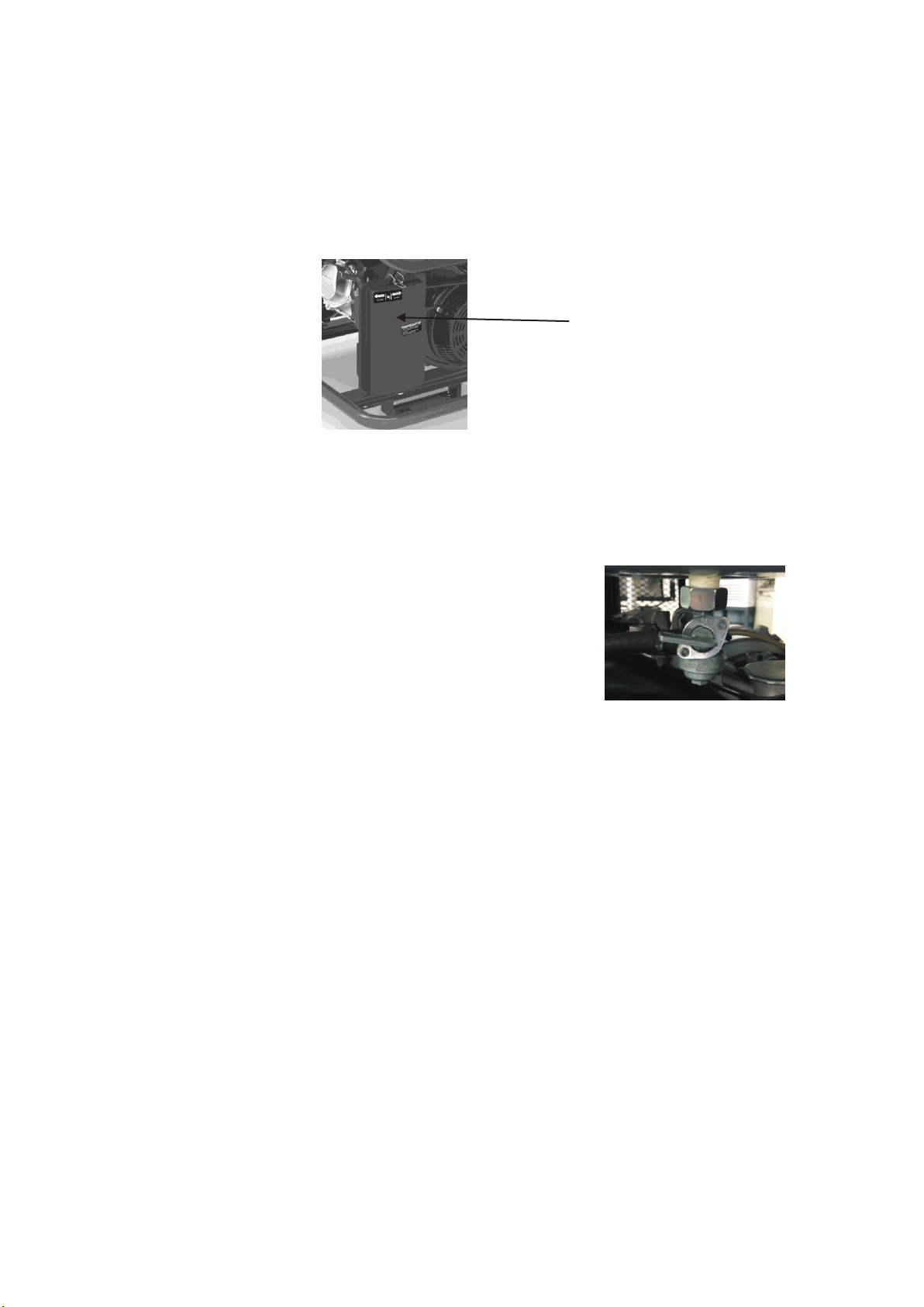
FUEL VALVE CUP CLEANING
The fuel valve cup is a small well underneath the fuel valve. It helps to
trap dirt and water that may be in the fuel tank before it can enter the
engine. To clean the fuel valve cup:
1. Turn the fuel valve to the “OFF” position.
2. Unscrew the fuel valve cup from the fuel valve using a wrench. Turn
the valve toward you and unscrew.
3. Clean the cup of all sediments using a rag or brush.
4. Reinstall the fuel valve cup.
SPARK PLUG MAINTENANCE
Spark plug: F6TC
The spark plug is important for proper engine operation. A good spark plug should be intact, free of
deposits, and properly gapped. Refer to Recommended Maintenance Schedule.. To inspect the spark plug:
1. Remove spark plug boot. Be careful not to tear insulation or wire.
2. Unscrew the spark plug from the engine using the spark plug wrench provided. There is limited space
for the wrench to turn. Use both rows of holes in the spark plug wrench to gain leverage to loosen the
plug.
3. Visually inspect the spark plug for cracks or excessive electrode wear. Replace as necessary.
4. Measure the plug gap with a wire gauge. The gap should be 0.7 to 0.8 mm (0.028-0.031 in).
5. If re-using the spark plug, use a wire brush to clean any dirt from around the spark plug base then
re-gap the spark plug.
6. Screw the spark plug back into the spark plug hole using the spark plug wrench. Do not over-tighten
spark plug. Recommended tightening of spark plug is 1/2 to 3/4 of a turn after spark plug gasket contacts
spark plug hole. Reinstall the spark plug boot.
Air Cleaner
Cover
Page 18

18
DRAINING THE FUEL TANK
Clean fuel tank each year or before storing the generator for extended periods of time. To drain the fuel
tank and carburetor:
1. Turn the fuel valve to the “OFF” position.
2. Remove the fuel line between the fuel valve and carburetor. Caution: A small amount of fuel may
leak from the hose during removal.
3. Attach a fuel line (not included with the generator) to the exposed end of the fuel valve.
4. Position fuel line into an appropriate container and open the fuel valve allowing fuel to flow into the
container.
5. Once fuel is drained, shut off the fuel valve.
6. Start and run the engine until fuel runs out.
7. Remove the fuel valve cup (See “FUEL VALVE CUP CLEANING”).
8. Empty the fuel valve cup of any fuel and clean.
9. Reinstall the fuel valve cup.
10. Store the emptied gasoline in a suitable place.
CAUTION: Do not store fuel for more than 3 months.
Page 19
19
HIGH ALTITUDE OPERATION ABOVE 3000 FEET
The fuel system on this generator may be influenced by operation at higher altitudes. Proper operation
can be ensured by installing an altitude kit at altitudes higher than 3000 feet above sea level. At elevations
above 8000 feet, the engine may experience decrease performance, even with the proper main jet.
Operating this generator without the proper altitude kit installed may increase the engine’s emissions and
decrease fuel economy and performance. The kit should be installed by a qualified mechanic.
WARNING! To prevent serious injury from fire: Follow kit procedures in a well-ventilated area away
from ignition sources. If the engine is hot from use, shut the engine off and wait for it to cool before
proceeding.
Notice: Warranty Void if necessary adjustments are not made for high altitude use.
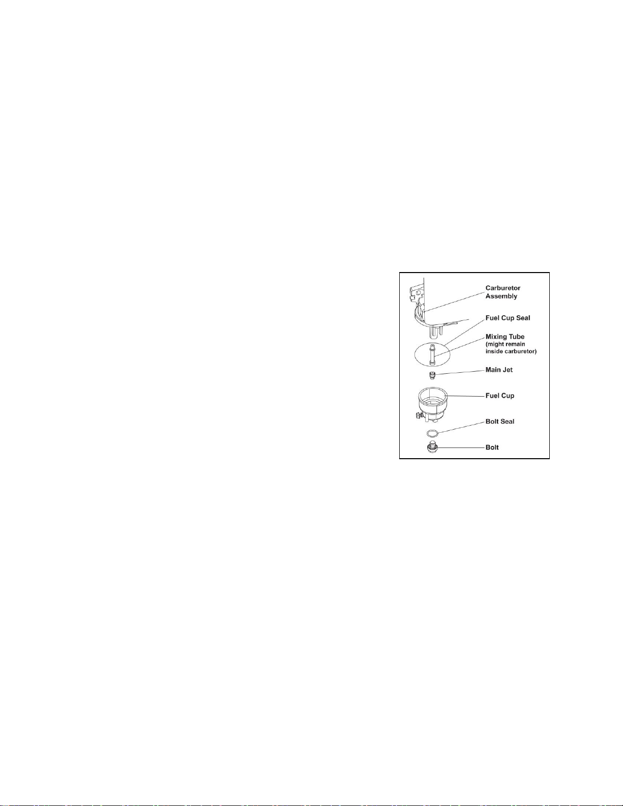
The altitude kit (PS48-115) includes below parts: bolt seal, fuel cup seal and main jet.
High Altitude Kit Installation Instructions
1. Turn off the engine.
2. Close the fuel valve.
3. Place a bowl under the fuel cup to catch any spilled fuel.
4. Unthread the bolt holding the fuel cup.
Caution! Carburetor bowl may have gas in it which will leak upon
removing the bolt.
5. Remove the bolt, bolt seal, fuel cup, fuel cup seal and main jet from
the body of the carburetor assembly.
6. Replace the main jet with the replacement jet needed for your
altitude range.
Note: The fuel cup seal and bolt seal may be damaged during removal
and should be replaced with the new ones from the kit.
7. Replace the Fuel Cup Seal, fuel cup, Bolt seal and bolt. Tighten in
place.
8. Wipe up any spilled fuel and allow excess to evaporate before starting engine. To prevent FIRE, do
not start the engine while the smell of fuel hangs in the air.
Page 20

20
STORAGE & TRANSPORT PROCEDURES
CAUTION: Never place any type of storage cover on the generator while it is still hot.
If the generator is being stored for short periods of time (30 to 60 days), add stabilized fuel to the fuel tank
until full. NOTE: Filling the tank reduces the amount of air in the tank and helps reduce deterioration of
fuel. Run the engine for 2 – 3 minutes allowing stabilized fuel mixture to circulate through the carburetor.
When storing the generator for extended periods of time:
• Drain the fuel tank (see “Draining the Fuel Tank” in the “Maintenance” section).
• Change oil.
• Do not obstruct any ventilation openings.
• Keep the generator in a cool dry area.
When transporting generator:
• Tighten fuel cap and vacuum relief valve. Drain the fuel tank if possible (see “Draining the Fuel
Tank” in the “Maintenance” section).
• Keep the generator upright. Never place the generator side down. Doing so will make it difficult to
start.
TROUBLESHOOTING
Problem
Cause
Solution
Engine
will not
start.
Engine switch is set to "OFF".
Set engine switch to "ON".
Fuel valve is turned to "OFF".
Turn fuel valve to "ON" position.
Choke is open.
Close the choke.
Engine is out of gas.
Add gasoline.
Engine is filled with contaminated or old gas.
Change the gas in the tank. Drain the gas in
the carburetor.
Spark plug is dirty.
Clean spark plug.
Spark plug is broken.
Replace spark plug.
Generator is not on level surface.
Move generator to a level surface to prevent
low oil shutdown from triggering.
Oil is low.
Add or replace oil.
Air cleaner is dirty.
Clean or replace air cleaner element.
Engine
runs but
there is no
output.
Circuit breaker button is off.
Wait for 2 minutes and move the circuit
breaker button to the "ON" position.
Bad connecting wires/cables.
If you are using an extension cord, try a
different one.
Bad electrical device connected to generator.
Try connecting a different device.
Generator
runs but
doesn’t
support all
electrical
devices
connected.
Generator is overloaded.
Perform these steps:
1. Turn off all electrical devices.
2. Unplug all electrical devices.
3. Turn off generator.
4. Wait several minutes.
5. Restart generator.
6. Try to connect fewer electrical loads
to the generator.
Short in one of the connected devices.
Try disconnecting any faulty or
short-circuited electrical loads.
Air cleaner is dirty.
Clean or replace air cleaner.
Page 21
21
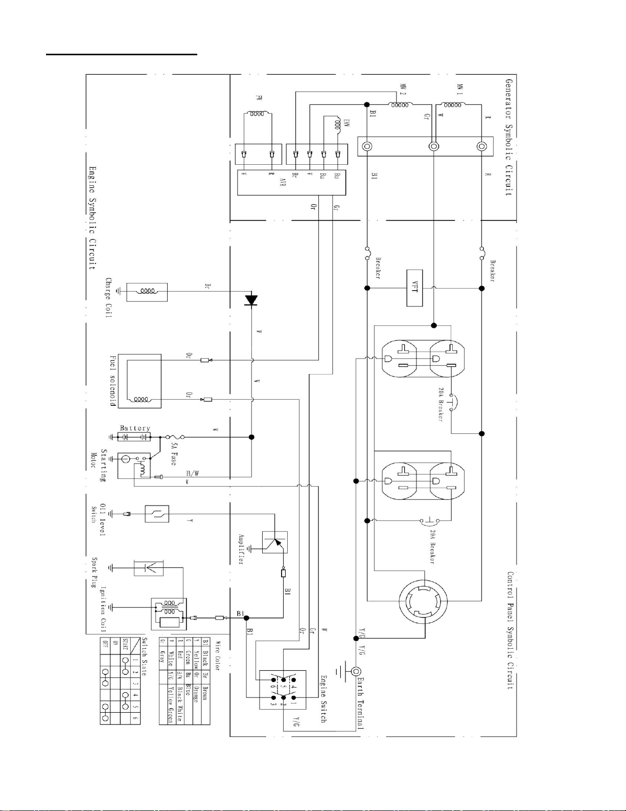
WIRING DIAGRAM
Page 22
22
EXPLODED VIEW AND PARTS LIST
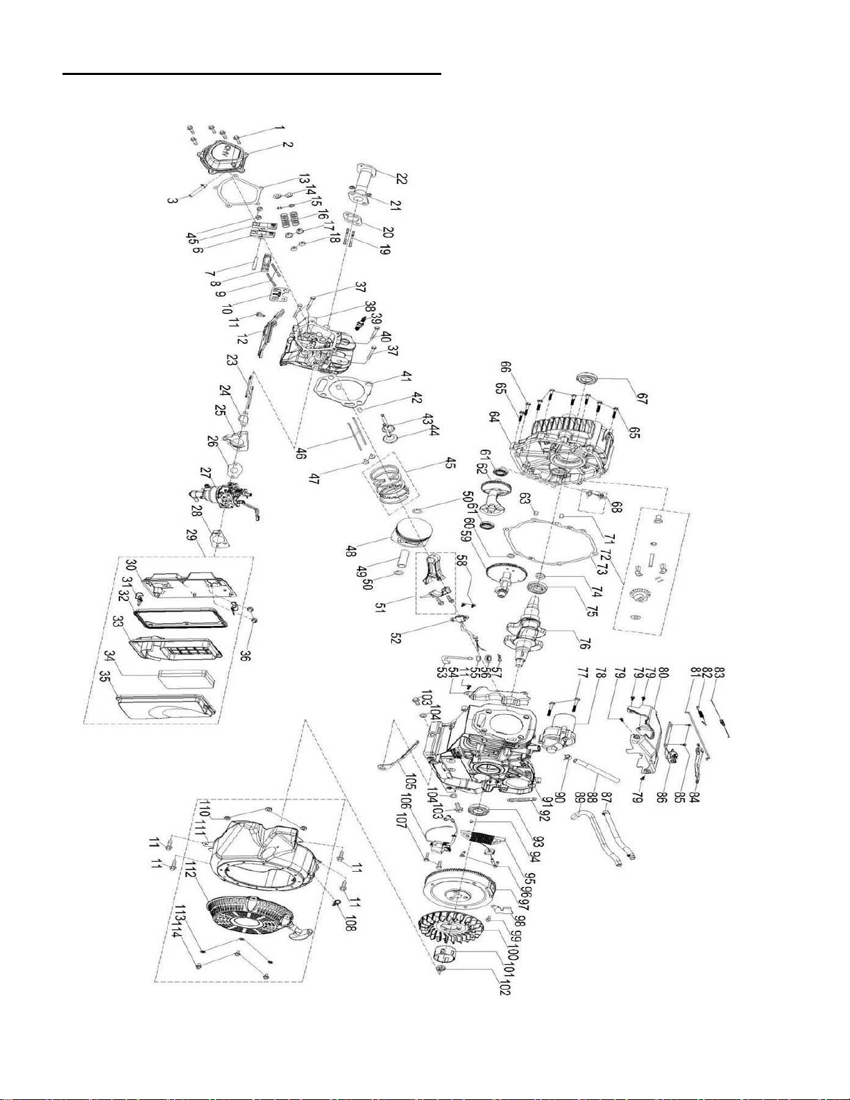
Engine exploded view
Page 23

23
Engine parts list
Item
Stock #
Description
Qty Item
Stock #
Description
Qty
1
PS48-001
Bolt M6×16
5 57
PS48-057
Cotter Pin
1 2 PS48-002
Cylinder Head Cover
1 58
PS48-058
Bolt M6×16
2
3
PS48-003
Breather Hose
1 59
PS48-059
Camshaft
1
4
PS48-004
Nut M6
2 60
PS48-060
Washer
1 5 PS48-005
Rocker Arm Assembly
1 61
PS48-061
Bearing 6202
2 6 PS48-006
Rocker Arm Assembly
1 62
PS48-062
Balance Shaft
1 7 PS48-007
Rocker Arm Shaft
1 63
PS48-063
Pin 9×12
1 8 PS48-008
Rocker Arm Base
1 64
PS48-064
Crankcase Cover
1
9
PS48-009
Bolt 2
65
PS48-065
Bolt M8×38
7
10
PS48-010
Rocker Arm Base
1 66
PS48-066
Bolt M8×45
1
11
PS48-011
Bolt M6×12
6 67
PS48-067
Oil Seal
1
12
PS48-012
Shroud
1 68
PS48-068
Dipstick
1
13
PS48-013
Head Cover Gasket
1 71
PS48-071
Pin, φ7×14
1
14
PS48-014
Valve Spring Seat
2 72
PS48-072
Governor Gear
1
15
PS48-015
Valve Locker
4 73
PS48-073
Crankcase Gasket
1
16
PS48-016
Valve Spring
2 74
PS48-074
Washer
1
17
PS48-017
Valve Seal
2 75
PS48-075
Bearing TM6207E
1
18
PS48-018
Valve Seat
2 76
PS48-076
Crankshaft
1
19
PS48-019
Stud M8×35
2 77
PS48-077
Bolt 2 20
PS48-020
Muffler Gasket
1 78
PS48-078
Starter Motor
1
21
PS48-021
Nut M8
2 79
PS48-079
Bolt M6×16
4
22
PS48-022
Exhaust Pipe
1 80
PS48-080
Cylinder Head Baffle
1
23
PS48-023
Stud M6×104
2 81
PS48-081
Throttle Linkage
1
24
PS48-024
Carburetor Insulator Gasket
1 82
PS48-082
Governor Spring
1
25
PS48-025
Insulator
1 83
PS48-083
Idle Spring
1
26
PS48-026
Carburetor Gasket
1 84
PS48-084
Governor Lever
1
27
PS48-027
Carburetor
1 85
PS48-085
Bolt M8×14
2
28
PS48-028
Air Filter Gasket
1 86
PS48-086
Governor Gear Bracket
1
29
PS48-029
Air Filter Assembly
1 87
PS48-087
Fuel Hose
1
30
PS48-030
Air Filter Base
1 88
PS48-088
Fuel Hose 4×10×565
1
31
PS48-031
Air Filter Clip
2 89
PS48-089
Fiberglass Tube 10×390
1
32
PS48-032
Air Filter Seal
1 90
PS48-090
Clamp
1
33
PS48-033
Air Filter Baffle
1 91
PS48-091
Crankcase
1
34
PS48-034
Air Filter Element
1 92
PS48-092
Clip 1 35
PS48-035
Air Filter Cover
1 93
PS48-093
Oil Seal 35×52×7
1
36
PS48-036
Nut M6
2 94
PS48-094
Bush 1 37
PS48-037
Bolt M10×1.25×87
3 95
PS48-095
Charging Coil
1
38
PS48-038
Cylinder Head
1 96
PS48-096
Bolt M6×30
2
39
PS48-039
Spark Plug
1 97
PS48-097
Flywheel
1
40
PS48-040
Bolt M10×1.25×65
1 98
PS48-098
Wire Board
1
41
PS48-041
Cylinder Head Gasket
1 99
PS48-099
Bolt M6×8
1
42
PS48-042
Pin 12×20
2 100
PS48-100
Cooling Fan
1
43
PS48-043
Exhaust Valve
1 101
PS48-101
Starter Cup
1
44
PS48-044
Intake Valve
1 102
PS48-102
Nut M16×1.5
1
45
PS48-045
Piston Ring Set
1 103
PS48-103
Drain Bolt
2
46
PS48-046
Push Rod
2 104
PS48-104
Washer
2
47
PS48-047
Tappet
2 105
PS48-105
Shroud
1
48
PS48-048
Piston
1 106
PS48-106
Ignition Coil
1
49
PS48-049
Piston Pin
1 107
PS48-107
Bolt M6×28
2
50
PS48-050
Circlip
2 108
PS48-108
Clip
1
51
PS48-051
Connecting Rod Assembly
1 110
PS48-110
Nut M6
3
52
PS48-052
Oil Sensor
1 111
PS48-111
Blower Housing
1
53
PS48-053
Governor Gear Shaft
1 112
PS48-112
Recoil Starter
1
54
PS48-054
Shroud
1 113
PS48-113
Washer
3
55
PS48-055
Washer
1 114
PS48-114
Bolt M6×10
3
56
PS48-056
Oil Seal
1 115
PS48-115
Altitude Kit
1
Page 24
24
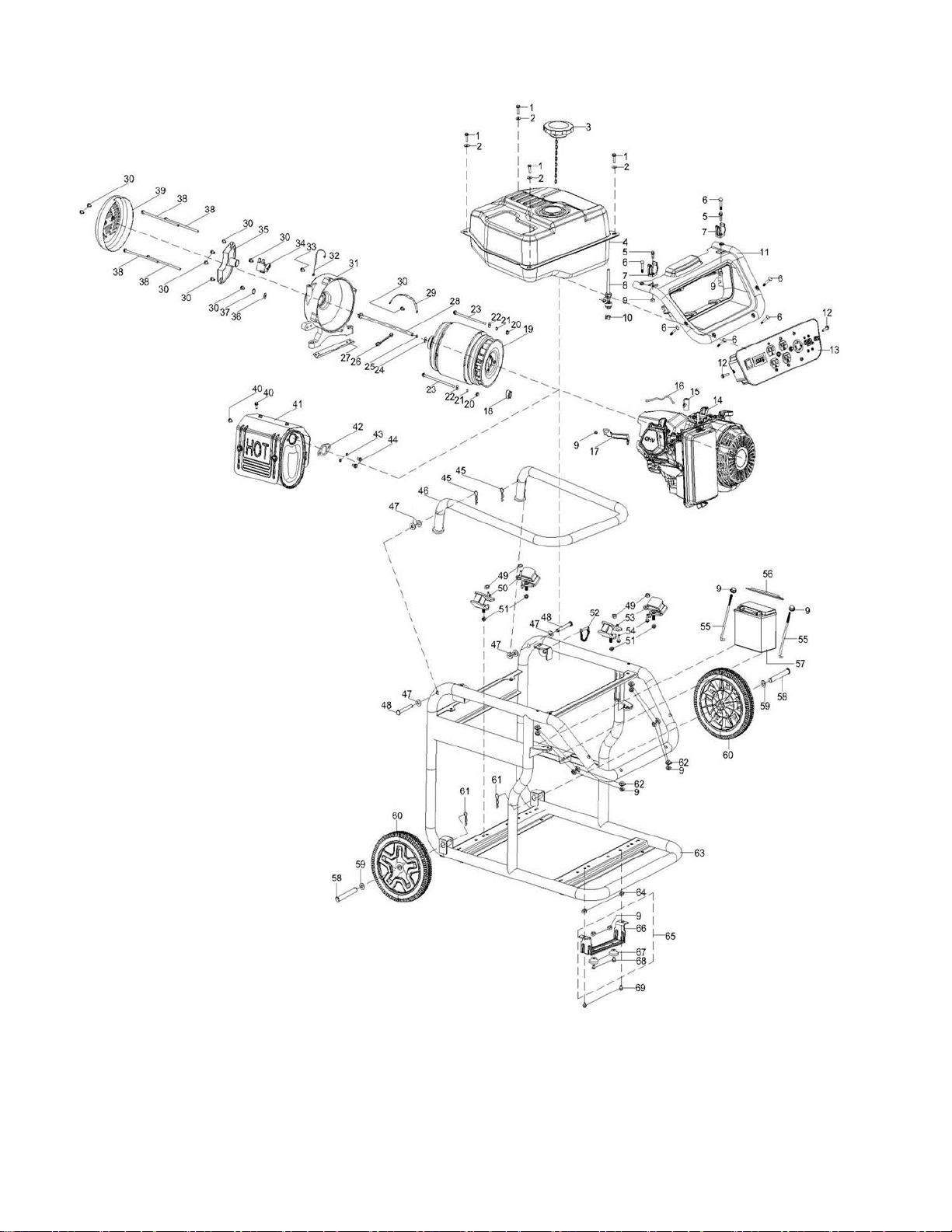
Generator exploded view
Page 25

25
Generator parts list
Item
Stock #
Description
Qty
Item
Stock #
Description
Qty
1
PS48-201
Bolt M6×25
4
35
PS48-235
Voltage Regulator
1 2 PS48-202
Washer
4
36
PS48-236
Washer 6
1
3
PS48-203
Fuel Tank Cap
1
37
PS48-237
Spring Washer 6
1
4
PS48-204
Fuel Tank
1
38
PS48-238
Bolt M6×194
4 5 PS48-205
Screw M6×20
2
39
PS48-239
End Cover
1 6 PS48-206
Bolt 6 40
PS48-240
Bolt M8×16
2 7 PS48-207
Circlip
2
41
PS48-241
Muffler
1 8 PS48-208
Fuel Valve
1
42
PS48-242
Muffler Gasket
1
9
PS48-209
Nut M6
13
43
PS48-243
Spring Washer 8
2
10
PS48-210
Clamp
1
44
PS48-244
Bolt M8×32
2
11
PS48-211
Panel Shroud
1
45
PS48-245
Circlip
2
12
PS48-212
Bolt M6×18
2
46
PS48-246
Handle
1
13
PS48-213
Control Panel
1
47
PS48-247
Nylon Washer
6
14
PS48-214
Engine
1
48
PS48-248
Pin 10×75
2
15
PS48-215
Clip 1 49
PS48-249
Nut M10×1.25
4
16
PS48-216
Positive Cable
1
50
PS48-250
Damping Pad A
2
17
PS48-217
Air Filter Bracket
1
51
PS48-251
Nut, M8
4
18
PS48-218
Plug 1 52
PS48-252
Pin 1 19
PS48-219
Alternator
1
53
PS48-253
Damping Pad B
2
20
PS48-220
Nut 2 54
PS48-254
Bolt M10×1.25×40
2
21
PS48-221
Spring Washer 5
2
55
PS48-255
Bolt
2
22
PS48-222
Washer 5
2
56
PS48-256
Binder Plate
1
23
PS48-223
Bolt M5×229
2
57
PS48-257
14Ah Battery
1
24
PS48-224
Washer 10
1
58
PS48-258
wheel Shaft
2
25
PS48-225
Spring Washer 10
1
59
PS48-259
Washer
2
26
PS48-226
Ground Wire
1
60
PS48-260
Wheel
2
27
PS48-227
Rear Bracket Support
1
61
PS48-261
Cotter Pin
2
28
PS48-228
Bolt M10×1.25×280
1
62
PS48-262
Washer
6
29
PS48-229
Cable Tie
1
63
PS48-263
Frame Assembly
1
30
PS48-230
Bolt M5×14
9
64
PS48-264
Nut M8
2
31
PS48-231
Rear Bracket
1
66
PS48-266
Front Foot
1
32
PS48-232
Negative Cable
1
67
PS48-267
Rubber Foot
2
33
PS48-233
Bolt M6×12
1
68
PS48-268
Bolt M6×18
2
34
PS48-234
Carbon Brush
1
69
PS48-269
Bolt M8×16
2
Page 26

26
TWO (2) YEARS LIMITED WARRANTY
PowerSmart is committed to building tools that are dependable for years. Our warranties are consistent with our
commitment and dedication to quality.
TWO (2) YEARS LIMITED WARRANTY OF POWER SMART PRODUCTS FOR HOME USE.
PowerSmart (“Seller") warrants to the original purchaser only, that all PowerSmart consumer power tools will be
free from defects in material or workmanship for a period of two (2) years from date of purchase. Ninety (90) days
for all PowerSmart Products, if the tool is used for professional or commercial use.
SELLER’S SOLE OBLIGATION AND YOUR EXCLUSIVE REMEDY under this Two (2) Years Limited
Warranty and, to the extent permitted by law, any warranty or condition implied by law, shall be the repair or
replacement of parts, without charge, which are defective in material or workmanship and which have not been
misused, carelessly handled, or misrepaired by persons other than Seller or Authorized Service Center. To make a
claim under this Limited Warranty, you must return the entire power tool product; transportation prepaid, to
PowerSmart Include a legible copy of the original receipt, which lists the date of purchase (month and year) and the
name of the company purchased from.
THIS LIMITED WARRANTY DOES NOT APPLY TO ANY ACCESSORY ITEMS INCLUDED WITH THE
TOOL SUCH AS CIRCULAR SAW BLADES OTHER RELATED ITEMS OR TO ANY REPLACEMENT
PARTS LISTED UNDER MAINTENANCE.
ANY IMPLIED WARRANTIES SHALL BE LIMITED IN DURATION TO TWO (2) YEARS FROM DATE OF
PURCHASE. SOME STATES IN THE U.S. AND SOME CANADIAN PROVINCES DO NOT ALLOW
LIMITATIONS ON HOW LONG AN IMPLIED WARRANTY LASTS, SO THE ABOVE LIMITATION MAY
NOT APPLY TO YOU.
IN NO EVENT SHALL SELLER BE LIABLE FOR ANY INCIDENTAL OR CONSEQUENTIAL DAMAGES
(INCLUDING BUT NOT LIMITED TO LIABILITY FOR LOSS OF PROFITS) ARISING FROM THE SALE
OR USE OF THIS PRODUCT. SOME STATES IN THE U.S. AND SOME CANADIAN PROVINCES DO NOT
ALLOW THE EXCLUSION OR LIMITATION OF INCIDENTAL OR CONSEQUENTIAL DAMAGES, SO
THE ABOVE LIMITATION OR EXCLUSION MAY NOT APPLY TO YOU.
THIS LIMITED WARRANTY GIVES YOU SPECIFIC LEGAL RIGHTS, AND YOU MAY ALSO HAVE
OTHER RIGHTS WHICH VARY FROM STATE TO STATE IN THE U.S., PROVINCE TO PROVINCE IN
CANADA AND FROM COUNTRY TO COUNTRY.
For questions / comments, technical assistance or repair parts –
Please call toll free at: 1-800-791-9458 (M-F 9am – 5pm CST)
Email: support@amerisuninc.com
SAVE YOUR RECEIPTS. THIS WARRANTY IS VOID WITHOUT THEM.
 Loading...