

Page 1
MODEL-DB7001
Questions, problems, missing parts? If you have questions or need technical support, call the
Amerisun customer service department at 1-800-791-9458 or visit Amerisuninc.com or e-mail
support@amerisuninc.com. For engine related problems, questions and warranty service call the engine
manufacturer 1-877-274-2214.
WARNING! Read and follow all safety rules and instructions in this manual before attempting to operate this
machine. Failure to comply with these instructions may result in personal injury. Save these instructions. This
unit is equipped with an internal combustion engine and may spark resulting in fire or explosion if used near
combustible material or fluid. O
meeting applicable local or state laws (if any). The spark arrester shall be maintained in effective working
order by operator.
nly use when the engine's exhaust system is equi
pped with a spark arrester
Page 2

TABLE OF CONTENTS
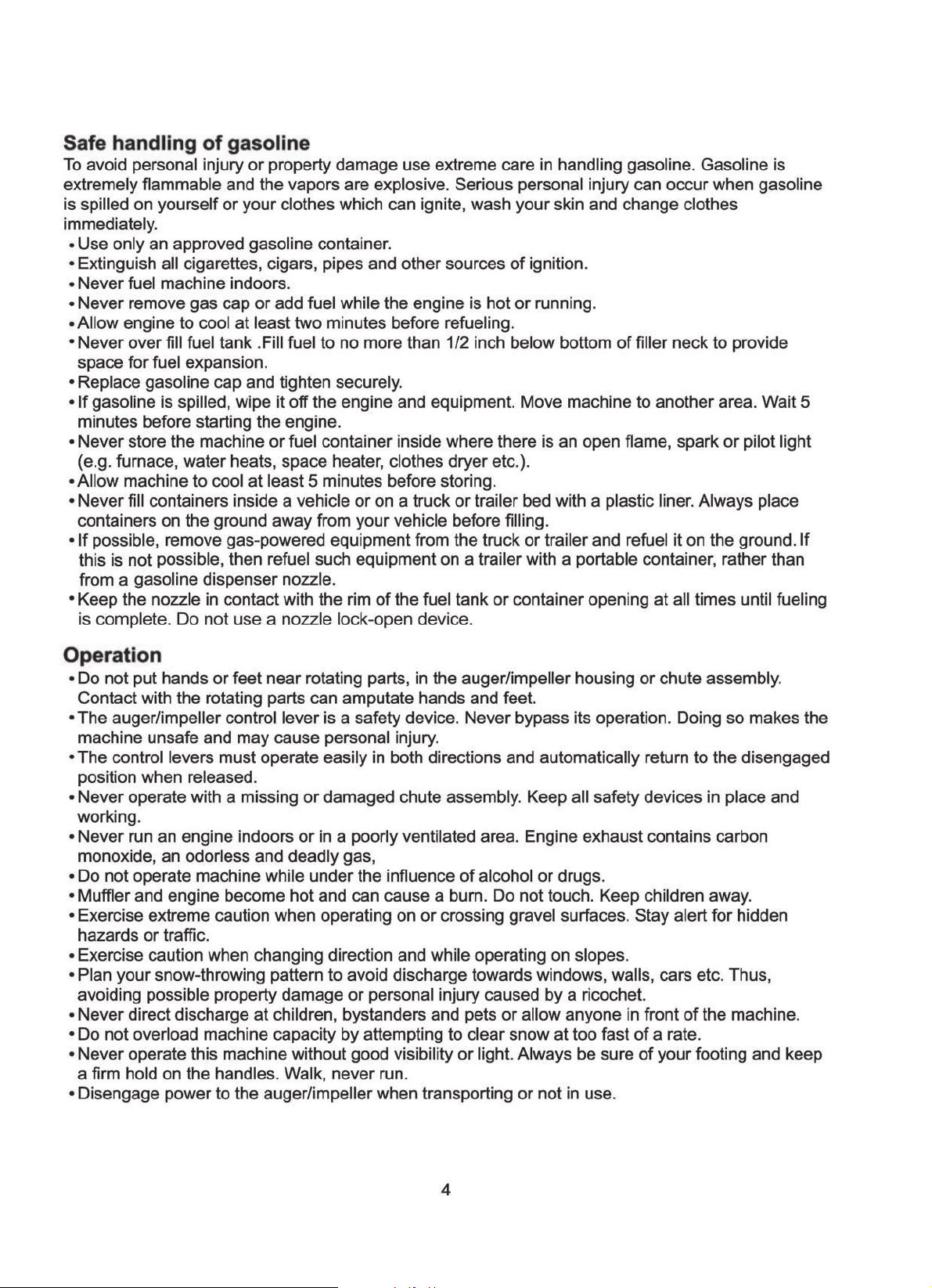
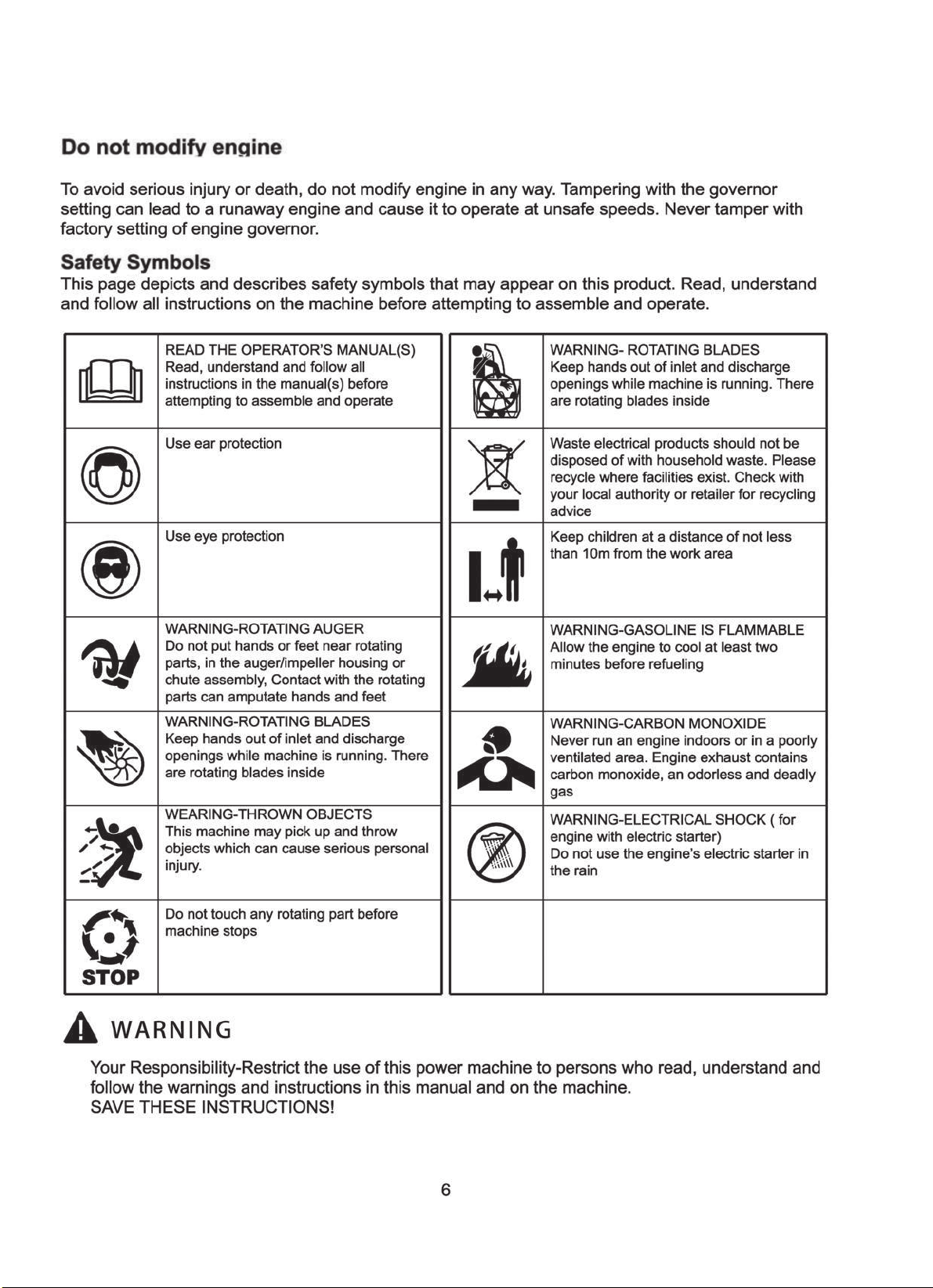
Safety
Safety Symbols
Feature Idenfitication
Box Contents
Assembly
Preparing Youe Snow Thrower
Operation
................................................................................................................................ 3
................................................................................................................. 6
........................................................................................................ 7
.................................................................................................................. 8
........................................................................................................................ 10
....................................................................................... 13
........................................................................................................................ 14
Recommended Maintenance Schedule
Troubleshooting
Warranty
........................................................................................................................ 19
............................................................................................................. 18
......................................................................... 16
Page 3
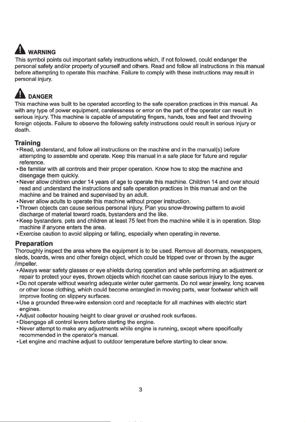
Safety
Page 4
Page 5
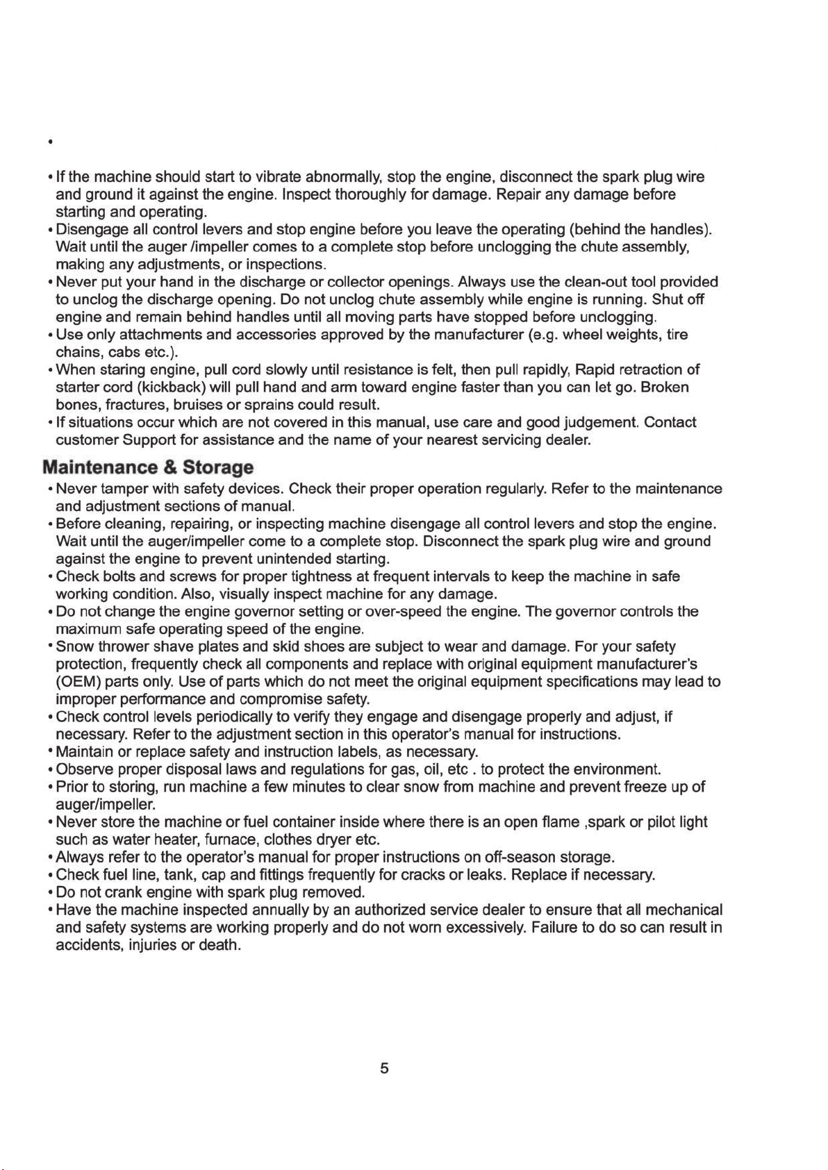
Never operate machine at high speeds on slippery surfaces. Look down and behind and
use care when backing up.
Page 6
Page 7

Feature Identification
TECHNICAL SPECIFICATIONS
TECHNICAL SPECIFICATIONS
Clearing Wisth:21 inches
Clearing Height:12.5 inches
Engine Displacement:208cc,4stroke
A
B
A- Auger Control
B- Chute Assembly
C- Shave Plate
D- Chute Handle
E- Auger
-
C
E
D
For a complete parts breakdown go to www.amerisuninc.com
Page 8

BOX CONTENTS
Check to ensure all of the following items are included:
a. Snow Thrower (1)
b. Chute Assembly (discharge chute, chute deflector and hardware, chute rotation
handle and hardware)
Located in Accessory Parts Bag:
a. Oil funnel (1)
b. Spark Plug wrench (1)
c. Operator ’s Manual (1)
d. Registration Card (1)
e. Easy set-up guide (1)
Page 9

1
2
3
4
1. Oversized Gas Cap
Allows for easy opening and closing for more efficient refueling.
2. Primer Bulb
The Primer Bulb system is designed to enrichen the fuel mixture for
starting a cold engine. DO NOT over prime the fuel system. To properly
use the Primer Bulb system, depress Primer Bulb 3 times maximum
when starting a cold engine. Do not use Primer Bulb system when
attempting to start a warm engine.
3. Safety Key Switch
The Safety key switch enables the engine electrical system and must be
installed to start the engine.
4. Oversized Recoil Handle
The engine is started by pulling the Recoil Handle. Always grip firmly and
have your body positioned properly when pulling. When starting the
engine:
a. Slowly pull Recoil Handle until resistance is felt.
b. Then pull firmly the full length of the rope to start engine.
c. Never wrap thumb around Recoil Handle in the event of engine Kick-back.
9
Page 10

Assembly
Control Cable Attachment
Auger Control
Installing the Upper Handle
2. Remove 2 knobs, bolts, and washers from
lower handles.
Insert bolts going from the middle going out,
3.
then curved washer, and knob. Tighten firmly
by hand.
Control cable
2
3
Page 11

Chute Assembly
4. Remove bolt, washers and nuts from chute seat.
5. Place chute, and handle over discharge hole. Insert
bolts from the inside through the holes, washers,
then nuts. Wrench tighten.
4
Page 12

7.Loosen the knobs on the top of the chute
assembly and pivot the upper chute up or
down to the desired angle. Tighten the
knobs before operating the snow thrower.
8. Use the chute handle to position the direction
you want to throw the snow.
Note: Never lift the unit by the chute handle.
8
Chute h andle
Recoil Holder
9. Put recoil handle into the holder on the upper
handle.
9
Page 13

Use unleaded gasoline with 87 octane or higher.
87
oil,do not overfill.
Engine uses 16-18 ounces of
Page 14

1. The choke switch position as shown picture
(after the machine start the choke switch
should be pulled to the left to the operation
state)
Run
Start
1
2.
3.
4.
-
(Please refer to as bellow “PULL START PROCEDURE” )
PULL START PROCEDURE
fig.1
3
2
Recoil handle
fig.2
Page 15

Engaging the Drive
Lift up slightly on the handle to allow the rubber paddles on the auger to contact the pavement and
propel the snow thrower forward. Pushing downward on the handle will raise the augers off the
ground and stop the forward motion.
Note: Excessive upward pressure on the handle will result in premature wear on the rubber auger
blades and is not covered by the warranty.
Engaging the Augers
To engage the augers and start throwing snow, squeeze the Auger Control against the handle.
Release to stop the augers.
STOPPING THE ENGINE (fig.3)
Pull out the red safety key to stop the engine. Keep in a safe place.
Must be reinserted to start the engine.
Safety key
Page 16

Auger Control Cable Adjustment
The auger cable is located on the left side(when standing behind the snow blower) and is made
up of an upper and lower cable connected by an adjustment plate. The adjustment plate is located
in-line with the cable below the control handle and is covered by a black plastic slip cover. The
adjustment plate is used to adjust auger belt tension.
1
1- Upper Auger Cable (Always in upper center hole)
5
2- Adjustment Plate
3- Lower Auger Cable
1
4- Adjustment Plate Lower Cable Opening
5- Slip Cover
2
3
4
1.Stop the engine.
2.Disconnect the upper cable from the auger
control handle.
3. Slide up the slip cover to access the
adjustment plate.
4. Adjustment is made by changing the position
of the lower cable in the adjustment plate
3
holes(1 to9).
Only move the lower cable diagonally
one hole at a time from its original position.
U p p e r
C a b le
Note: The upper cable end must be in the
upper single center hole of the adjustment
plate. Do not change the position of the upper
cable.
5. Connect the upper cable to the control handle.
6. Start the engine and engage the auger to test
the operation of the auger.
Test the snow thrower to see if there is a noticeable difference.
If after the adjustment to the control cable the auger still hesitates
when rotating, the belt may need to be replaced, please call our service
department for assistance.
2
L es s Ten s io n
8
7
9
M o re Ten s io n
23456
1
L o w e r
C a b le
16
Page 17

Page 18

Page 19

TWO YEAR WARRANTY
Amerisun Inc. and LCT Engine Corporation jointly warrant this product for two years
against defects in material or workmanship when used for normal residential purposes.
The manufacturer will, at its option, repair or replace, for the original purchaser, any
part or parts which have been found to be defective in material and workmanship.
Residential use means use of the product on the same lot as your home.
• If you have questions or problems, or before returning this product, call
toll-free 1-800-791-9458 or email support@amerisuninc.com
This warranty covers product defects only. Neither Amerisun nor LCT Engine
Corporation is liable for indirect, incidental, or consequential damages in connection
with the use of PowerSmart Products covered by this warranty, including any cost or
expense of providing substitute equipment or service during reasonable periods of
mal-function or non-use pending completion of repairs under this warranty.
Transportation to and from the services center is the responsibility of the consumer.
Some states do not allow exclusions of incidental or consequential damages, so the
above exclusions may not apply to you. This warranty gives you specific legal rights,
and you may also have other rights which vary from state to state.
DISCLAIMER
The information contained within this manual is the latest information as of the publication date. All contents
are subject to change without notice. This manual is intended as a guide.
procedures visit amerisuninc.com.
19
For the latest information and
Amerisun Inc., ITASCA, IL
C 2015
 Loading...