

Page 1
User Manual
Centurion Tower Online UPS
6000/10000
Uninterruptible Power Supply System
NetGuard
UPS Monitoring Software
®
IMPORTANT
Download the latest NetGuard Monitoring Software:
http://powershield.com.au/index.php/downloads
NetGuard default password is: administrator
Page 2
Introduction
Thank you for choosing PowerShield.
PowerShield Centurion UPS series are designed to provide the highest level of protection
against disturbances found on electrical power supply lines. It is suitable for most applications
including IT, security, telephone, broadcasting, medical etc.
The Centurion UPS series are designed to provide the most comprehensive protection for your
valuable electronic equipment, hardware, software and data from harmful disturbances found
on AC power lines including blackouts, power sags, power surges, under voltage, over voltage,
line noise, frequency variation, switching transients and harmonic distortions. The Centurions
true online double conversion topology will continuously protect your equipment by internally
isolating your equipment from the utility power ensuring that all your equipment always
receives clean, uninterrupted and stable power.
Very Important !! : WARRANTY REGISTRATION
In order to validate product warranty, it is essential that you register your UPS on line.
Please Visit PowerShield on line product warranty web page
www.powershield.com.au/product-registration.php
This user manual contains instructions relating to safety, installation, operation, maintenance
and warranty of this product.
Please keep this manual in a safe place for future references.
Handling Safety
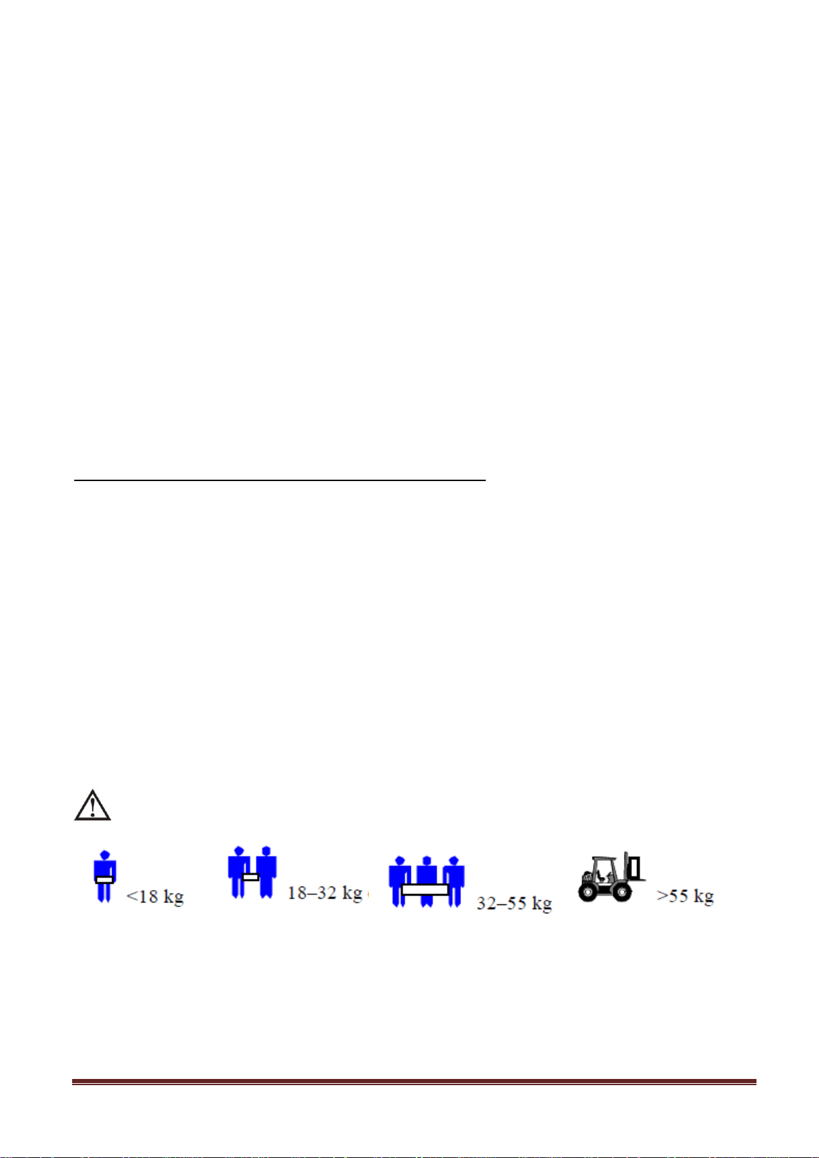
Do not lift heavy loads without assistance.
This equipment is intended for installation in a controlled temperature indoor area free from
conductive contaminants.
www.powershield.com.au 1
Page 3

CAUTION !
Please comply with all warnings and operating
instructions in this manual strictly.
Save this manual properly and read carefully the
following instructions before installing the unit.
Do not operate this unit before reading through
all safety information and operating instructions
carefully.
www.powershield.com.au 2
Page 4

Table of Contents
1. SAFETY AND EMC INSTRUCTIONS ....................................................................... 4
1-1. TRANSPORTATION AND STORAGE .................................................................................... 4
1-2. PREPARATION ........................................................................................................... 4
1-3. INSTALLATION ........................................................................................................... 4
1-4. OPERATION .............................................................................................................. 5
1-5. STANDARDS .............................................................................................................. 5
2. INSTALLATION AND OPERATION ......................................................................... 6
2-1. UNPACKING AND INSPECTION ........................................................................................ 6
2-2. REAR PANEL VIEW ..................................................................................................... 6
2-3. SINGLE UPS INSTALLATION .......................................................................................... 8
2-4. UPS INSTALLATION FOR PARALLEL SYSTEM ....................................................................... 9
2-5. SOFTWARE INSTALLATION .......................................................................................... 10
3. OPERATIONS ...................................................................................................... 11
3-1. BUTTON OPERATION ................................................................................................. 11
3-2. LED INDICATORS AND LCD PANEL ............................................................................... 11
3-3. AUDIBLE ALARM ...................................................................................................... 13
3-4. SINGLE UPS OPERATION ........................................................................................... 14
3-5. PARALLEL OPERATION ............................................................................................... 16
3-6. ABBREVIATION MEANING IN LCD DISPLAY ...................................................................... 17
3-7. LCD SETTING ......................................................................................................... 18
3-8. OPERATING MODE/STATUS DESCRIPTION ....................................................................... 22
3-9. FAULT CODE ........................................................................................................... 24
3-10. WARNING INDICATOR ............................................................................................. 24
4. TROUBLE SHOOTING .......................................................................................... 25
5. SERVICE…………………………………………………………………………………………26
6. CONTACTING PowerShield………………………………………………………………… 26
7. STORAGE AND MAINTENANCE ........................................................................... 27
7-1. STORAGE ............................................................................................................... 27
7-2. MAINTENANCE ........................................................................................................ 27
8. SPECIFICATIONS ................................................................................................ 28
www.powershield.com.au 3
Page 5
1. Safety and EMC instructions
Please read carefully the following user manual and the safety instructions before installing the unit or using
the unit!
1-1. Transportation and Storage
Please transport the UPS system only in the original package to protect against shock and
impact.
The UPS must be stored in the room where it is ventilated and dry.
1-2. Preparation
Condensation may occur if the UPS system is moved directly from cold to warm environment.
The UPS system must be absolutely dry before being installed. Please allow at least two hours for the
UPS system to acclimate the environment.
Do not install the UPS system near water or in moist environments.
Do not install the UPS system where it would be exposed to direct sunlight or nearby heater.
Do not block ventilation holes in the UPS housing.
1-3. Installation
Do not connect appliances or devices which would overload the UPS (e.g. big motor-type
equipment)) to the UPS output sockets or terminal.
Place cables in such a way that no one can step on or trip over them.
Do not block air vents in the housing of UPS. The UPS must be installed in a location with good
ventilation. Ensure enough space on each side for ventilation.
UPS has provided earthed terminal, in the final installed system configuration, equipotential
earth bonding to the external UPS battery cabinets.
The UPS can be installed only by qualified maintenance personnel.
An appropriate disconnect device as short-circuit backup protection should be provided in the
building wiring installation.
An integral single emergency switching device which prevents further supply to the load by the
UPS in any mode of operation should be provided in the building wiring installation.
Connect the earth before connecting to the building wiring terminal.
Installation and Wiring must be performed in accordance with the local electrical laws and
regulations.
www.powershield.com.au 4
Page 6
1-4. Operation
* Safety
IEC/EN 62040-1-1
* EMI
Conducted Emission...............................:IEC/EN 62040-2
Category C3
Radiated Emission..................................:IEC/EN 62040-2
Category C3
*EMS
ESD.........................................................:IEC/EN 61000-4-2
Level 4
RS........................................................ ...:IEC/EN 61000-4-3
Level 3
EFT......................................................... :IEC/EN 61000-4-4
Level 4
SURGE................................................... :IEC/EN 61000-4-5
Level 4
CS........................................................... :IEC/EN 61000-4-6
Level 3
Power-frequency Magnetic field.............. :IEC/EN 61000-4-8
Level 3
Low Frequency Signals............................:IEC/EN 61000-2-2
Warning: This is a product for commercial and industrial application in the
second environment-installation restrictions or additional measures may be
needed to prevent disturbances.
Do not disconnect the earth conductor cable on the UPS or the building wiring terminals in any
time since this would cancel the protective earth of the UPS system and of all connected loads.
The UPS system features its own, internal current source (batteries). The UPS output sockets or
output terminal blocks may be electrically live even if the UPS system is not connected to the building
wiring outlet.
In order to fully disconnect the UPS system, first press the “OFF” button and then disconnect the
mains.
Ensure that no liquid or other foreign objects can enter into the UPS system.
The UPS can be operated by any individuals with no previous experience.
1-5. Standards
www.powershield.com.au 5
Page 7
2. Installation and Operation
Model #
Type
Model #
Type
PSCE6000
Standard
model
PSCE6000L
Long-run
model
PSCE10000
PSCE10000L
There are two different types of online UPS: standard and long-run models. Please refer to the following
model table.
We also offer optional parallel function for these two types by request. The UPS with parallel function is
called as “Parallel model”. We have described detailed installation and operation of Parallel Model in the
following chapter.
2-1. Unpacking and Inspection
Unpack the package and check the package contents. The shipping package contains:
● One UPS
● One user manual
● One PowerShield NetGuard UPS monitoring software CD
● One RS-232 cable
● One USB cable
● One EPO plug ( Fitted on the rear panel )
● One parallel cable (Option for Parallel operation model)
● One share current cable (Option for Parallel operation model)
● One battery cable (only available for long-run model)
NOTE: Before installation, please inspect the unit. Be sure that nothing inside the package is damaged
during transportation. Do not turn on the unit and notify the carrier and dealer immediately if there is any
damage or lacking of some parts. Please keep the original package in a safe place for future use.
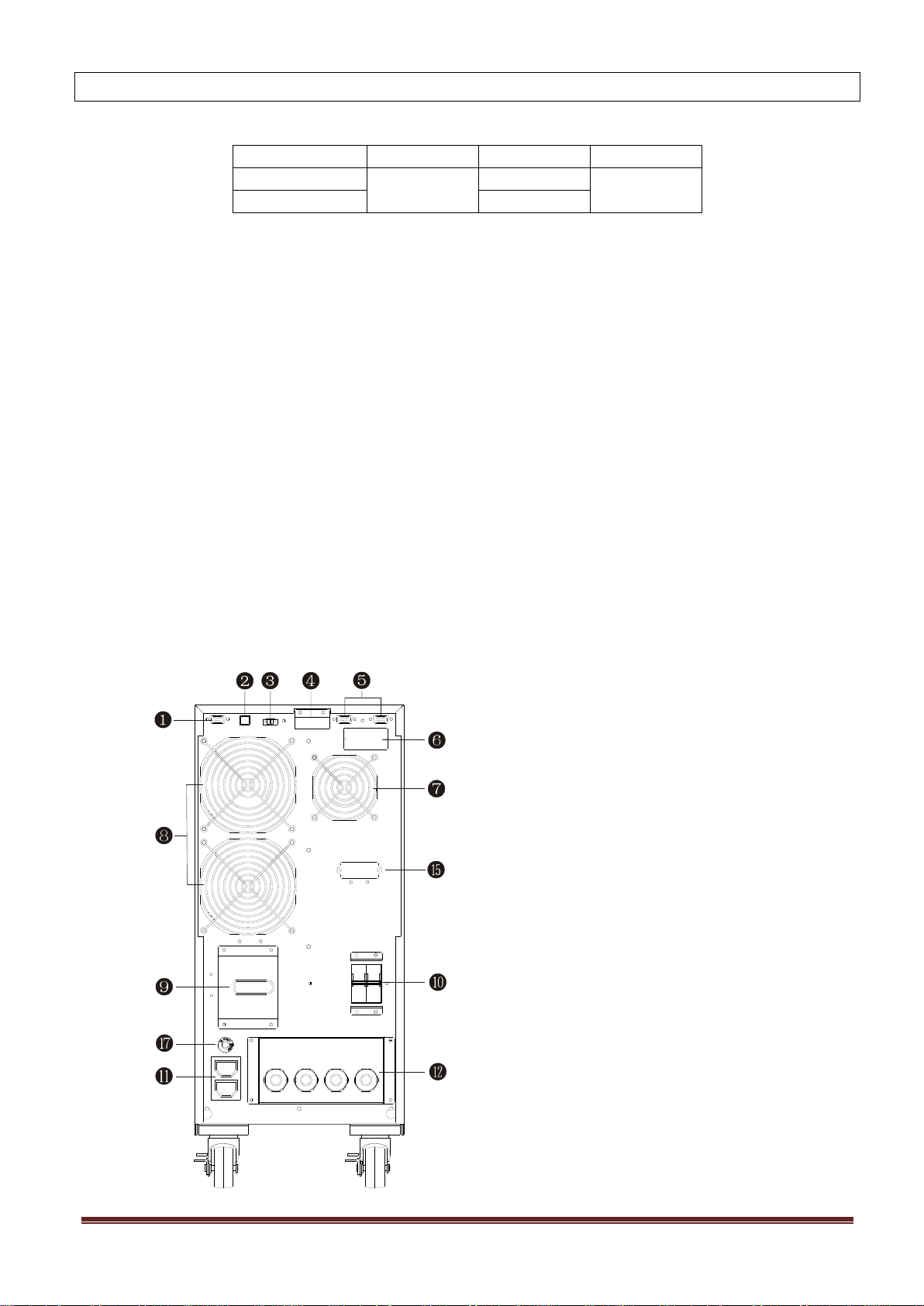
2-2. Rear Panel View
Diagram 1: Rear Panel Overlook
www.powershield.com.au 6
Page 8
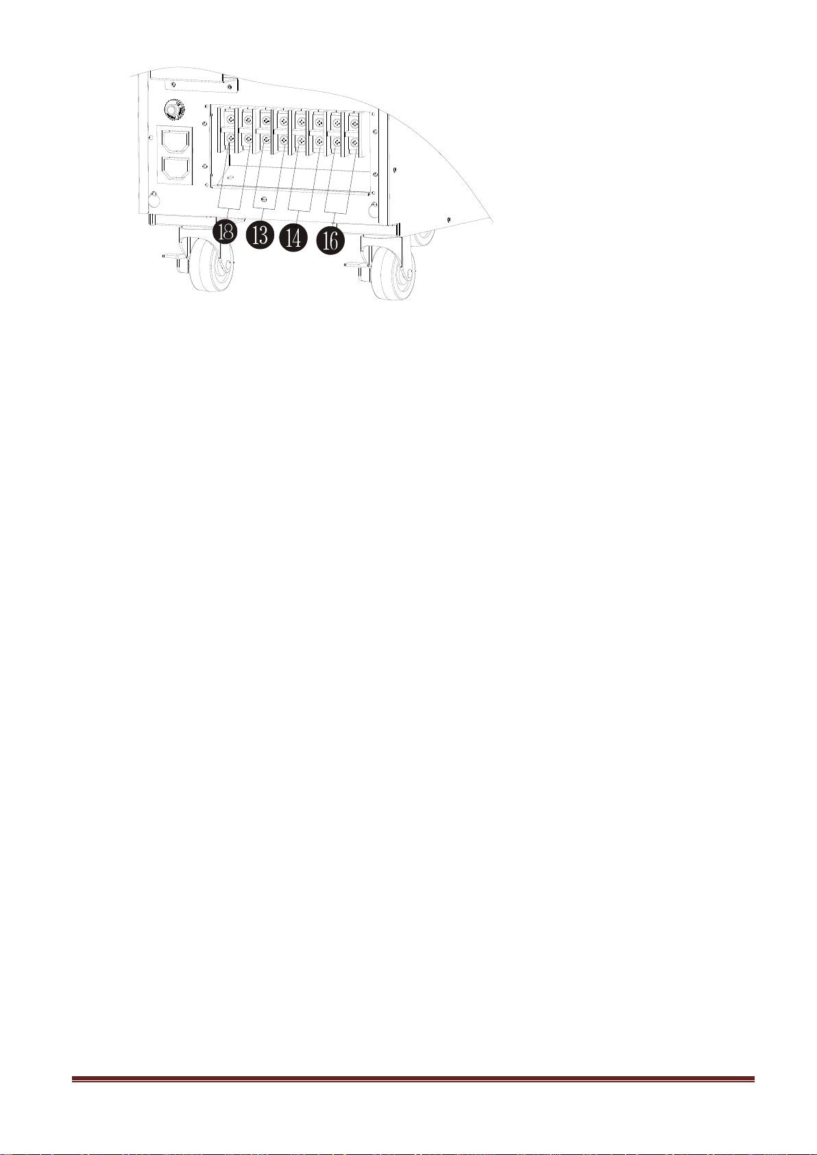
Diagram 2: Input/Output Terminal
1. RS-232 communication port
2. USB communication port
3. Emergency power off function connector (EPO connector)
4. Share current port (Option for Parallel operation model )
5. Parallel port (Option for Parallel operation model )
6. Intelligent slot for SNMP and AS400 cards
7. Charger fan
8. Power stage fan
9. Maintenance bypass switch
10. Input circuit breaker/External battery circuit breaker
11. Output receptacles: connect to mission-critical loads
12. Input/Output terminal (Refer to Diagram 2 for the details)
13. Output terminal: connect to mission-critical loads
14. Programmable output terminal: connect to non-critical loads
15. External battery terminal
16. Utility input terminal
17. Output circuit breaker for receptacles
18. External maintenance bypass switch signal
www.powershield.com.au 7
Page 9
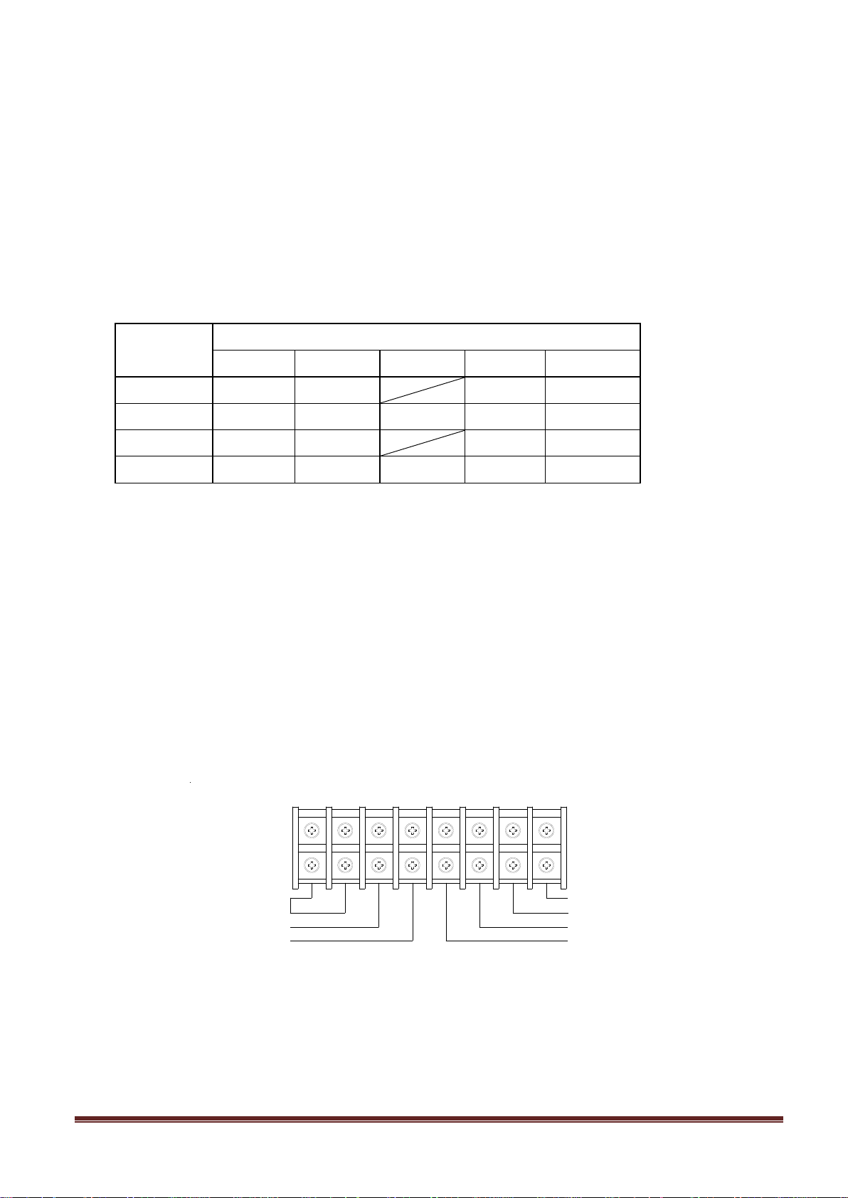
2-3. Single UPS Installation
Model
Wiring spec (AWG)
Input
Output
Battery
Ground
EMBS
PSCE6000
10
10 10
16
PSCE6000L
10
10
10
10
16
PSCE10000
8 8 8 16
PSCE10000L
8 8 8 8 16
Input Neutral
Input Line
Output 1 Line
Output 1 Neutral
Output 2 Line
Output 2 Neutral
EMBS
Installation and wiring must be performed in accordance with the local electric laws/regulations and execute
the following instructions by professional personnel.
1) Make sure the mains wire and breakers in the building are enough for the rated capacity of UPS to
avoid the hazards of electric shock or fire.
NOTE: Do not use the wall receptacle as the input power source for the UPS, as its rated current is less than
the UPS’s maximum input current. Otherwise the receptacle may be burned and destroyed.
2) Switch off the mains switch in the building before installation.
3) Turn off all the connected devices before connecting to the UPS.
4) Prepare wires based on the following table:
NOTE 1: The cable for PSCE6000/PSCE6000L should be able to withstand over 40A current. It is
recommended to use 10AWG or thicker wire for safety and efficiency.
NOTE 2: The cable for PSCE10000/PSCE10000 should be able to withstand over 63A current. It is
recommended to use 8AWG or thicker wire for safety and efficiency.
NOTE 3: The cable for EMBS terminal is recommended to use 16AWG or thicker wire to match the
terminal, the current in the cable is less than 5mA.
NOTE 4: The selections for color of wires should be followed by the local electrical laws and
regulations.
5) Remove the terminal block cover on the rear panel of UPS. Then connect the wires according to the
following terminal block diagrams: (Connect the earth wire first when making wire connection. Disconnect
the earth wire last when making wire disconnection!)
NOTE 1: Make sure that the wires are connected tightly with the terminals.
www.powershield.com.au 8
Terminal Block wiring diagram
Page 10
NOTE 2: There are two kinds of outputs: output terminal/outlets and programmable terminal.
Please connect non-critical devices to the programmable terminal and critical devices to the
output terminal/outlets. During power failure, you may extend the backup time to critical devices by
setting shorter backup time for non-critical devices.
NOTE 3: Please install the output breaker between the output terminal and the load, and the breaker
should be qualified with leakage current protective function if necessary.
6) Insert the EPO plug into the EPO slot on the rear panel.
7) If you want install the external maintenance bypass switch, please connect the micro switch of the
maintenance bypass switch to the EMBS, when the micro switch is on, the UPS will turn into bypass mode.
8) Put the terminal block cover back to the rear panel of the UPS.
Warning:
● Make sure the UPS is not turned on before installation. The UPS should not be turned on during wiring
connection.
● Do not try to modify the standard model to the long-run model. Particularly, do not try to connect the
standard internal battery to the external battery. The battery type and voltage may be different. If you
connect them together, it maybe causes the hazard of electric shock or fire!
Warning: (For connecting External battery bank )
● Make sure a DC breaker or other protection device between UPS and external battery pack is installed. If
not, please install it carefully. Switch off the battery breaker before installation.
NOTE: Set the battery pack breaker in “OFF” position and then install the battery pack.
● Pay attention to the rated battery voltage marked on the rear panel. If you want to change the
numbers of the battery pack, please make sure you modify the setting simultaneously. The connection
with wrong battery voltage may cause permanent damage of the UPS. Make sure the voltage of the
battery pack is correct.
● Pay attention to the polarity marking on external battery terminal block, and make sure the
correct battery polarity is connected. Wrong connection may cause permanent damage of the UPS.
● Make sure the protective earth ground wiring is correct. The wire current spec, color, position,
connection and conductance reliability should be checked carefully.
● Make sure the utility input & output wiring is correct. The wire current spec, color, position,
connection and conductance reliability should be checked carefully. Make sure the L/N site is correct, not
reverse and short-circuited.
2-4. UPS Installation for Parallel System
If the UPS is only available for single operation, you may skip this section to the next.
1) Install and wires the UPSs according to the section 2-3.
2) Connect the output wires of each UPS to an output breaker.
3) Connect all output breakers to a major output breaker. Then this major output breaker will directly
connect to the loads.
4) Each UPS is connected to an independent battery pack.
NOTE: The parallel system cannot use one battery pack. Otherwise, it will cause system permanent failure.
www.powershield.com.au 9
Page 11
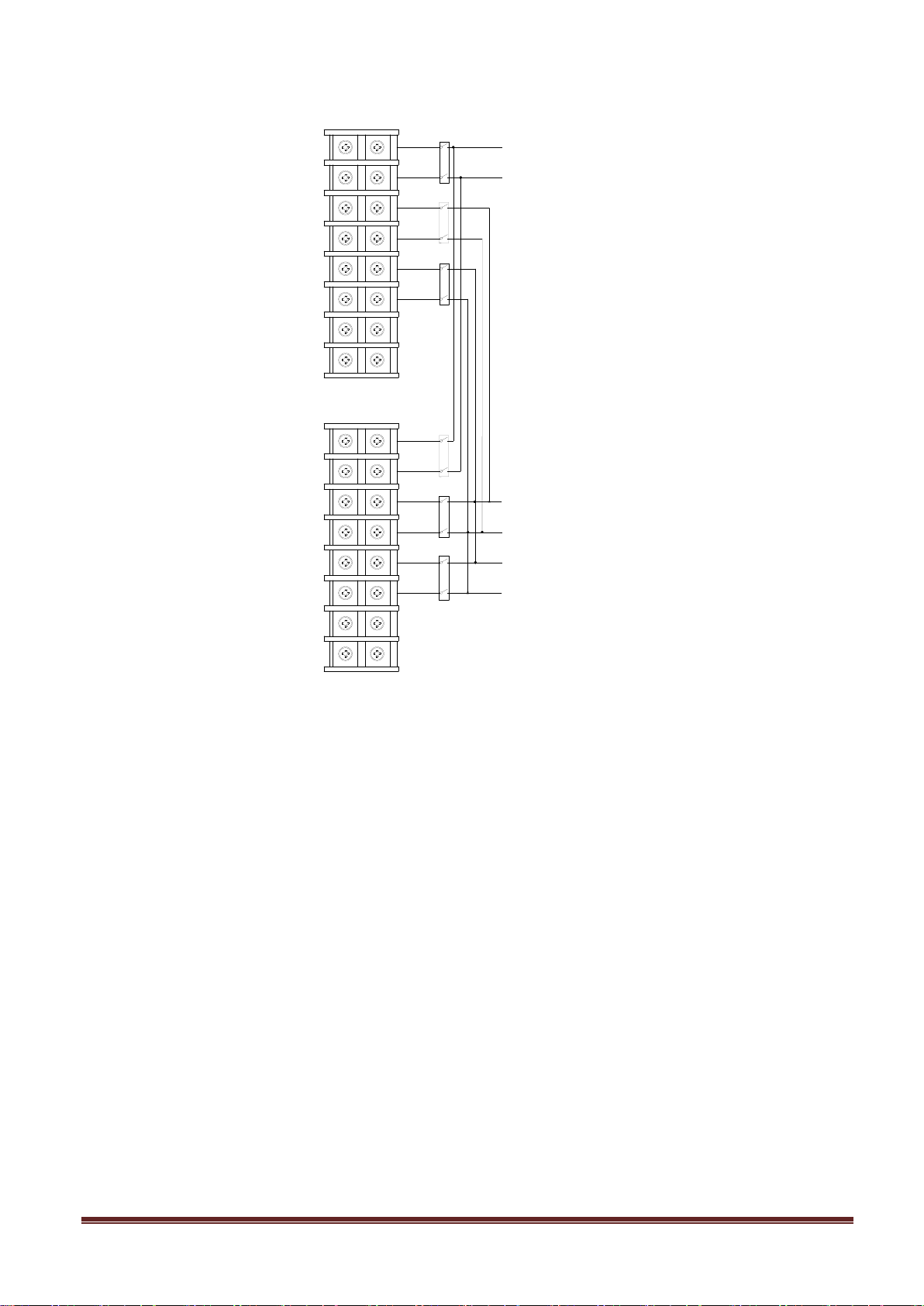
5) Refer to the following wiring diagram:
UPS1
L
N
L
N
L
N
UPS2
L
N
L
N
L
N
Input Neutral
Input Line
Output 1 Line
Output 1 Neutral
Output 2 Neutral
Output 2 Line
Wiring diagram of parallel system
2-5. Software Installation
For optimal computer system protection, install PowerShield NetGuard UPS monitoring software to fully
configure UPS shutdown.
www.powershield.com.au 10
Page 12
3. Operations
Button
Function
ON/Enter Button
Turn on the UPS: Press and hold the button more than 0.5s to turn on the UPS.
Enter Key: Press this button to confirm the selection in setting menu.
OFF/ESC Button
Turn off the UPS: Press and hold the button more than 0.5s to turn off the UPS.
Esc key: Press this button to return to last menu in setting menu.
Test/Up Button
Battery test: Press and hold the button more than 0.5s to test the battery while
in AC mode, or CVCF mode.
UP key: Press this button to display next selection in setting menu.
Mute/Down Button
Mute the alarm: Press and hold the button more than 0.5s to mute the buzzer.
Please refer to section 3-4-9 for details.
Down key: Press this button to display previous selection in setting menu.
Test/Up +
Mute/Down Button
Press and hold the two buttons simultaneous more than 1s to enter/escape the
setting menu.
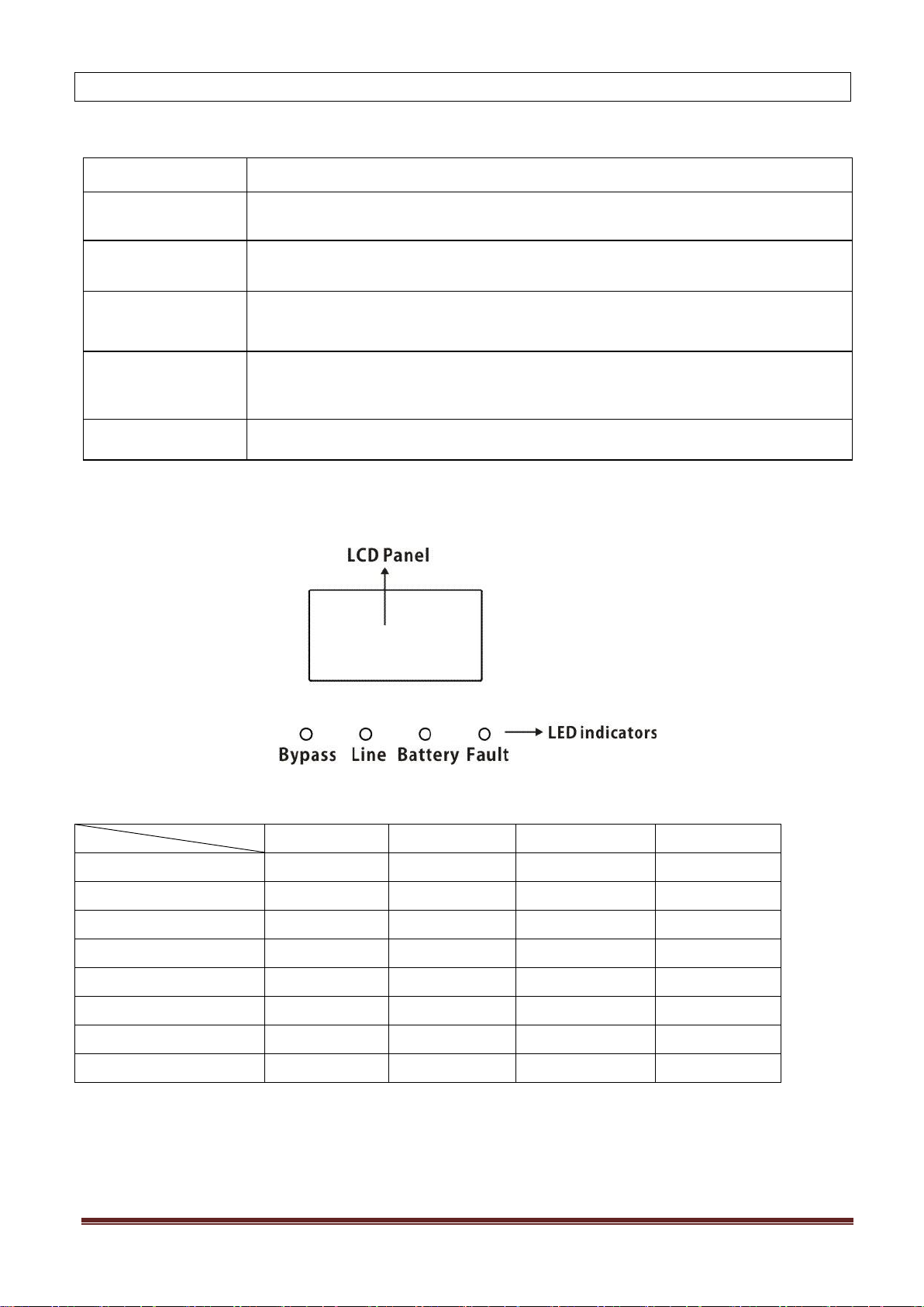
Mode LED
Bypass
Line
Battery
Fault
UPS Startup
● ● ●
●
Bypass mode
●
○ ○ ○
AC mode
○ ● ○
○
Battery mode
○
○ ● ○
CVCF mode
○ ● ○
○
Battery Test
● ● ●
○
ECO mode
●
●
○
○
Fault
○ ○ ○
●
3-1. Button Operation
* CVCF mode means converter mode.
3-2. LED Indicators and LCD Panel
LED Indicators:
There are 4 LEDs on front panel to show the UPS working status:
Note: ● means LED is ON, and ○ means LED is OFF.
www.powershield.com.au 11
Page 13
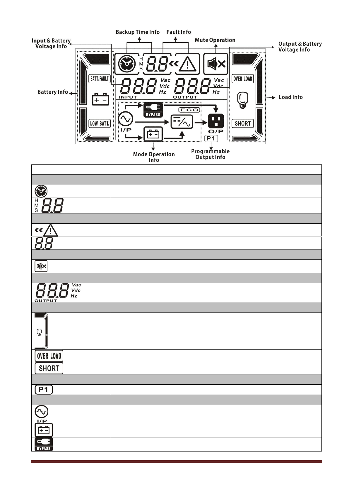
LCD Panel:
Display
Function
Backup time information
Indicates the backup time in pie chart.
Indicates the backup time in numbers.
H: hours, M: minutes, S: seconds
Fault information
Indicates that the warning and fault occurs.
Indicates the fault codes, and the codes are listed in details in section 3-9.
Mute operation
Indicates that the UPS alarm is disabled.
Output & Battery voltage information
Indicates the output voltage, frequency or battery voltage.
Vac: output voltage, Vdc: battery voltage, Hz: frequency
Load information
Indicates the load level by 0-25%, 26-50%, 51-75%, and 76-100%.
Indicates overload.
Indicates the load or the output is short.
Programmable output information
Indicates that the programmable outputs are working.
Mode operation information
Indicates the UPS connects to the mains.
Indicates the battery is working.
Indicates the bypass circuit is working.
www.powershield.com.au 12
Page 14
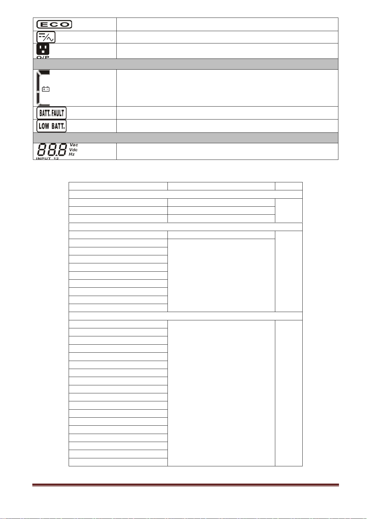
Indicates the ECO mode is enabled.
Indicates the Inverter circuit is working.
Indicates the output is working.
Battery information
Indicates the Battery capacity by 0-25%, 26-50%, 51-75%, and 76-100%.
Indicates the battery is fault.
Indicates low battery level and low battery voltage.
Input & Battery voltage information
Indicates the input voltage or frequency or battery voltage.
Vac: Input voltage, Vdc: battery voltage, Hz: input frequency
3-3. Audible Alarm
Description
Buzzer status
Muted
UPS status
Bypass mode
Beeping once every 2 minutes
Yes
Battery mode
Beeping once every 4 seconds
Fault mode
Beeping continuously
Warning
Overload
Beeping twice every second
No
Low battery
Beeping once every second
Battery unconnected
Over charge
EPO enable
Fan failure/Over temperature
Charger failure
IP fuse broken
Overload 3 times in 30min
EPO status
Fault
Bus start failure
Beeping continuously
Yes
Bus over
Bus under
Bus unbalance
Bus short circuited
Inverter soft start failure
High Inverter voltage
Low Inverter voltage
Inverter output short circuited
Negative power fault
Battery SCR short circuited
Inverter relay short circuited
Battery voltage loss
Parallel communication failure
Output short circuited
Over temperature
CPU communication failure
Overload
www.powershield.com.au 13
Page 15

3-4. Single UPS Operation
1. Turn on the UPS with utility power supply (in AC mode)
1) After power supply is connected correctly, set the breaker of the battery pack at “ON” position (the
step only available for long-run model). Then set the input breaker at “ON” position. At this time
the fan is running and the UPS supplies power to the loads via the bypass. The UPS is operating in
Bypass mode.
NOTE: When UPS is in Bypass mode, the output voltage will directly power from utility after you
switch on the input breaker. In Bypass mode, the load is not protected by UPS. To protect your
precious devices, you should turn on the UPS. Refer to next step.
2) Press and hold the “ON” button for 0.5s to turn on the UPS and the buzzer will beep once.
3) A few seconds later, the UPS will enter to AC mode. If the utility power is abnormal, the UPS will
operate in Battery mode without interruption.
NOTE: When the UPS is running out battery, it will shut down automatically at Battery mode. When the
utility power is restored, the UPS will auto restart in AC mode.
2. Turn on the UPS without utility power supply (in Battery mode)
1) Make sure that the breaker of the battery pack is at “ON” position (only for long-run model).
2) Press and hold the “ON” button for 0.5s to turn on the UPS, and the buzzer will beep once.
3) A few seconds later, the UPS will be turned on and enter to Battery mode.
3. Connect devices to UPS
After the UPS is turned on, you can connect devices to the UPS.
1) Turn on the UPS first and then switch on the devices one by one, the LCD panel will display total
load level.
2) If it is necessary to connect the inductive loads such as a printer, the in-rush current should be
calculated carefully to see if it meets the capacity of the UPS, because the power consumption of
this kind of loads is too big.
3) If the UPS is overload, the buzzer will beep twice every second.
4) When the UPS is overload, please remove some loads immediately. It is recommended to have the
total loads connected to the UPS less than 80% of its nominal power capacity to prevent overload
for system safety.
5) If the overload time is over acceptable time listed in spec at AC mode, the UPS will automatically
transfer to Bypass mode. After the overload is removed, it will return to AC mode. If the overload
time is over acceptable time listed in spec at Battery mode, the UPS will become fault status. At this
time, if bypass is enabled, the UPS will power to the load via bypass. If bypass function is disabled
or the input power is not within bypass acceptable range, it will cut off output directly.
4. Charge the batteries
1) After the UPS is connected to the utility power, the charger will charge the batteries automatically
except in Battery mode or during battery self-test.
2) Suggest to charge batteries at least 10 hours before use. Otherwise, the backup time may be
shorter than expected time.
3) Make sure the battery numbers setting on the control board (Please refer to the section 3-4-12 for
detailed setting) is consistent to real connection.
www.powershield.com.au 14
Page 16

5. Battery mode operation
1) When the UPS is in Battery mode, the buzzer will beep according to different battery capacity. If the
battery capacity is more than 25%, the buzzer will beep once every 4 seconds; If the battery
voltage drops to the alarm level, the buzzer will beep quickly (once every sec) to remind users that
the battery is at low level and the UPS will shut down automatically soon. Users could switch off
some non-critical loads to disable the shutdown alarm and prolong the backup time (the UPS would
cut off the programmable output terminal automatically when the programmable timer function is
enabled). If there is no more load to be switched off at that time, you have to shut down all loads
as soon as possible to protect the devices or save data. Otherwise, there is a risk of data loss or
load failure.
2) In Battery mode, if buzzer sound annoys, users can press the Mute button to disable the buzzer.
3) The backup time of the long-run model depends on the external battery capacity.
4) The backup time may vary from different environment temperature and load type.
5) When setting backup time for 16.5 hours (default value from LCD panel), after discharging 16.5
hours, UPS will shut down automatically to protect the battery. This battery discharge protection
can be enabled or disabled through LCD panel control. (Refer to 3-7 LCD setting section)
6. Test the batteries
1) If you need to check the battery status when the UPS is running in AC mode/CVCF mode/ECO mode,
you could press the “Test” button to let the UPS do battery self-test.
2) To keep the system reliable, the UPS will perform the battery self-test automatically periodically.
The default setting period is once per week.
3) Users also can set battery self-test through monitoring software.
4) If the UPS is at battery self-test, the LCD display and buzzer indication will be the same as at
Battery mode except that the battery LED is flashing.
7. Turn off the UPS with utility power supply in AC mode
1) Turn off the inverter of the UPS by pressing “OFF” button for at least 0.5s, and then the buzzer will
beep once. The UPS will turn into Bypass mode.
NOTE 1: If the UPS has been set to enable the bypass output, it will bypass voltage from utility
power to output sockets and terminal even though you have turned off the UPS (inverter).
NOTE 2: After turning off the UPS, please be aware that the UPS is working at Bypass mode and
there is risk of power loss for connected devices.
2) In Bypass mode, output voltage of the UPS is still present. In order to cut off the output, switch off
the input breaker. A few seconds later, there is no display shown on the display panel and UPS is
complete off.
8. Turn off the UPS without utility power supply in Battery mode
1) Turn off the UPS by pressing “OFF” button for at least 0.5s, and then the buzzer will beep once.
2) Then UPS will cut off power to output and there is no display shown on the display panel.
9. Mute the buzzer
1) To mute the buzzer, please press the “Mute” button for at least 0.5s. If you press it again after the
buzzer is muted, the buzzer will beep again.
www.powershield.com.au 15
Page 17

2) Some warning alarms can’t be muted unless the error is fixed. Please refer to section 3-3 for the
details.
10. Operation in warning status
1) When Fault LED flashes and the buzzer beeps once every second, it means that there are some
problems for UPS operation. Users can get the fault code from LCD panel. Please check the trouble
shooting table in chapter 4 for details.
2) Some warning alarms can’t be muted unless the error is fixed. Please refer to section 3-3 for the
details.
11. Operation in Fault mode
1) When Fault LED illuminates and the buzzer beeps continuously, it means that there is a fatal error in
the UPS. Users can get the fault code from display panel. Please check the trouble shooting table
in chapter 4 for details.
2) Please check the loads, wiring, ventilation, utility, battery and so on after the fault occurs. Don’t try
to turn on the UPS again before solving the problems. If the problems can’t be fixed, please contact
the distributor or service people immediately.
3) For emergency case, please cut off the connection from utility, external battery, and output
immediately to avoid more risk or danger.
12. Operation of changing battery numbers
1) This operation is only available for professional or qualified technicians.
2) Turn off the UPS. If the load couldn’t be cut off, you should remove the cover of maintenance
bypass switch on the rear panel and turn the maintenance switch to “BPS” position first.
3) Switch off the input breaker, and switch off the battery breaker (only available for long-run model).
4) Remove the cabinet, and then modify the jumper on the control board to set the battery numbers
(refer to NOTE below). Then disconnect battery wire for standard model and modify the battery
pack carefully. After complete the changes, put the cabinet back.
NOTE: JP1 setting on the control board: please shorts the Pin5 & Pin6 and Pin7 & Pin8 for 20 pcs
batteries; shorts the Pin5 & Pin6 or Pin7 & Pin8 for 19 pcs batteries; and keeps every pin open for 18 pcs
batteries.
5) Switch on the input breaker and the UPS will enter Bypass mode. If the UPS is in maintenance
Bypass mode, turn the maintenance switch to “UPS” position and then turn on the UPS.
3-5. Parallel Operation
1. Parallel system connection
1) Make sure all of the UPSs are parallel models, and follow the wiring refer to section 2-3.
2) Turn off the input and output breakers of each UPS, and turn off the battery breaker if the UPS is
long-run model.
3) Remove the cover of parallel share current cable port on the UPS, connect each UPS one by one
with the parallel cable and share current cable, and then screw the cover back again.
4) Turn on the input breaker of the each UPS and measure the voltage difference between the output
line1 of each UPS with multimeter. If the voltage difference is less than 1V, it means all connections
are correct. If the difference is larger than 1V, check if the wirings are connected correctly.
www.powershield.com.au 16
Page 18
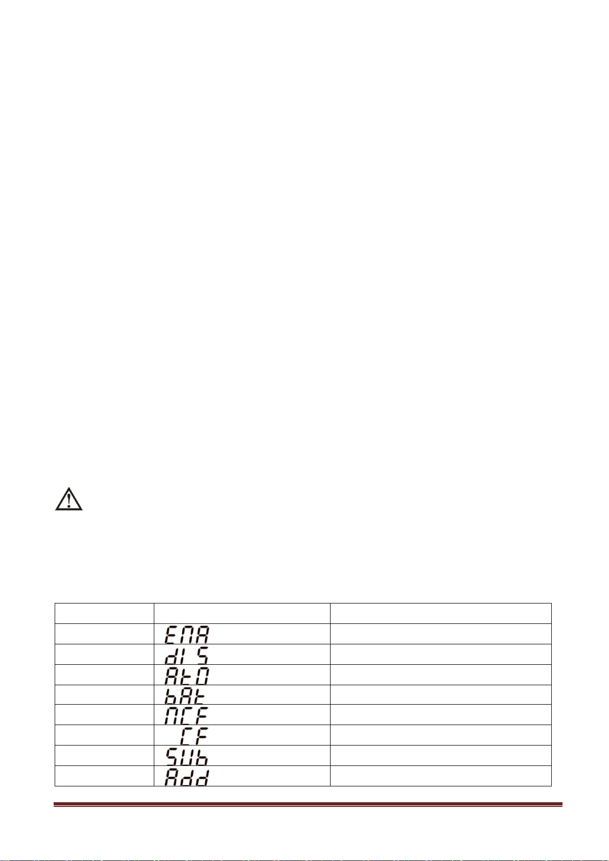
5) Turn on the input breakers of all UPSs in the parallel systems and turn on each UPS in turns. Make
Abbreviation
Display content
Meaning
ENA
Enable
DIS
Disable
ATO
Auto
BAT
Battery
NCF
Normal mode (not CVCF mode)
CF
CVCF mode
SUB
Subtract
ADD
Add
sure that AC mode LED or Battery mode LED displays in each UPS. Measure the output voltage of
each UPS to check if the voltage difference is less than 2V (typical 1V) with multimeter. If the
difference is more than 2V, please check that parallel cable or share current cable are connected
well. If they are all connected well, maybe it’s UPS internal issue. Please contact your local
distributor or service center for help.
6) Turn off each UPS in turns and after all of them transfer to Bypass mode, turn on the output
breaker of each unit.
7) Turn on the UPSs in the AC mode and then the parallel system connection is complete.
2. Add one new unit into the parallel system
1) You can not add one new unit into the parallel system when whole system is running. You must cut
off the load and shutdown the system.
2) Make sure all of the UPS are the parallel models, and follow the wiring refer to section 2-3.
3) Install the new parallel system refers to the previous section.
3. Remove one unit from the parallel system
1) If the bypass is abnormal, you can not remove the UPS without interruption. You must cut off the
load and shut down the system.
2) Make sure the bypass setting is enabled in each UPS and then turn off the running system. All UPSs
will transfer to Bypass mode. Remove all the maintenance bypass covers and set the maintenance
switches from “UPS” to “BPS”. Turn off the input breakers and battery breakers.
3) Remove the UPS that you want.
4) Turn on the input breaker of the remaining UPSs and the system will transfer to Bypass mode.
5) Set the maintenance switches from “BPS” to “UPS and put the maintenance bypass covers back.
Turn on the remaining UPSs and finish the parallel system connection.
Warning: (Only for the parallel system)
● Before turning on the parallel system to activate inverter, make sure that all unit’s maintenance switch
at the same position.
● When parallel system is turned on to work through inverter, please do not operate the maintenance
switch of any unit.
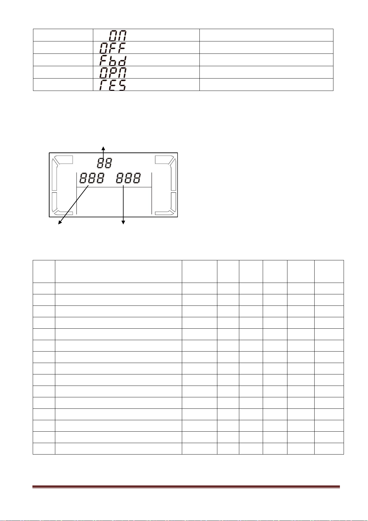
3-6. Abbreviation Meaning in LCD Display
www.powershield.com.au 17
Page 19
ON
On
OFF
Off
FBD
Not allowed
OPN
Allow
RES
Reserved
Parameter 1: It’s for program alternatives.
There are 15 programs to set up. Refer to below
table.
Parameter 2 and parameter 3 are the setting
options or values for each program.
Code
Description
Bypass
AC
ECO
CVCF
Battery
Battery
Test
01
Output voltage
Y
02
Output frequency
Y
03
Voltage range for bypass
Y
04
Frequency range for bypass
Y
05
ECO mode enable/disable
Y
06
Voltage range for ECO mode
Y
07
ECO mode frequency range setting
Y
08
Bypass mode setting
Y
Y
09
Battery backup time setting
Y Y Y Y Y
Y
10
Programmable output setting
Y Y Y Y Y
Y
11
Shutdown point for programmable output
Y Y Y Y Y
Y
12
Hot standby function enable/disable
Y Y Y Y Y
Y
13
Battery voltage adjustment
Y Y Y Y Y
Y
14
Charger voltage adjustment
Y Y Y Y Y
Y
15
Output voltage adjustment
Y
Y Y
Parameter 1
Parameter 2
Parameter 3
3-7. LCD Setting
There are three parameters to set up the UPS. Refer to following diagram.
14 programs available list for parameter 1:
*Y means that this program can be set in this mode.
www.powershield.com.au 18
Page 20
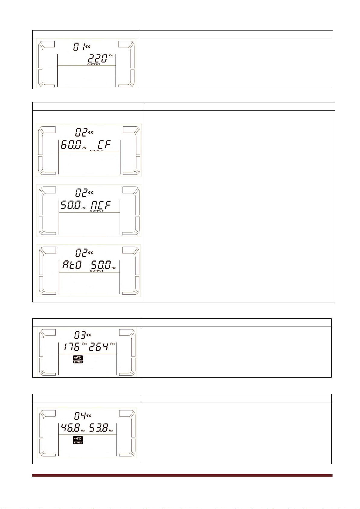
01: Output voltage
Interface
Setting
Parameter 3: Output voltage
You may choose the following output voltage in parameter 3:
208: Presents output voltage is 208Vac
220: Presents output voltage is 220Vac
230: Presents output voltage is 230Vac
240: Presents output voltage is 240Vac
Interface
Setting
60 Hz, CVCF mode
50 Hz, Normal mode
ATO
Parameter 2: Output Frequency
Setting the output frequency. You may choose following three
options in parameter 2:
50.0Hz: The output frequency is setting for 50.0Hz.
60.0Hz: The output frequency is setting for 60.0Hz.
ATO: If selected, output frequency will be decided according to
the latest normal utility frequency. If it is from 46Hz to 54Hz, the
output frequency will be 50.0Hz. If it is from 56Hz to 64Hz, the
output frequency will be 60.0Hz. ATO is default setting.
Parameter 3: Frequency mode
Setting output frequency at CVCF mode or not CVCF mode. You
may choose following two options in parameter 3:
CF: Setting UPS to CVCF mode. If selected, the output frequency
will be fixed at 50Hz or 60Hz according to setting in parameter 2.
The input frequency could be from 46Hz to 64Hz.
NCF: Setting UPS to normal mode (not CVCF mode). If selected,
the output frequency will synchronize with the input frequency
within 46~54 Hz at 50Hz or within 56~64 Hz at 60Hz according to
setting in parameter 2. If 50 Hz selected in parameter 2, UPS will
transfer to battery mode when input frequency is not within
46~54 Hz. If 60Hz selected in parameter 2, UPS will transfer to
battery mode when input frequency is not within 56~64 Hz.
*If Parameter 2 is ATO, the Parameter 3 will show the current
frequency.
Interface
Setting
Parameter 2: Set the acceptable low voltage for bypass. Setting
range is from 110V to 209V and the default value is 110V.
Parameter 3: Set the acceptable high voltage for bypass. Setting
range is from 231V to 276V and the default value is 264V.
Interface
Setting
Parameter 2: Set the acceptable low frequency for bypass.
50 Hz system: Setting range is from 46.0Hz to 49.0Hz.
60 Hz system: Setting range is from 56.0Hz to 59.0Hz.
The default value is 46.0Hz/56.0Hz.
Parameter 3: Set the acceptable high frequency for bypass.
50 Hz: Setting range is from 51.0Hz to 54.0 Hz.
60 Hz: Setting range is from 61.0Hz to 64.0Hz.
The default value is 54.0Hz/64.0Hz.
02: Output frequency
03: Voltage range for bypass
04: Frequency range for bypass
www.powershield.com.au 19
Page 21
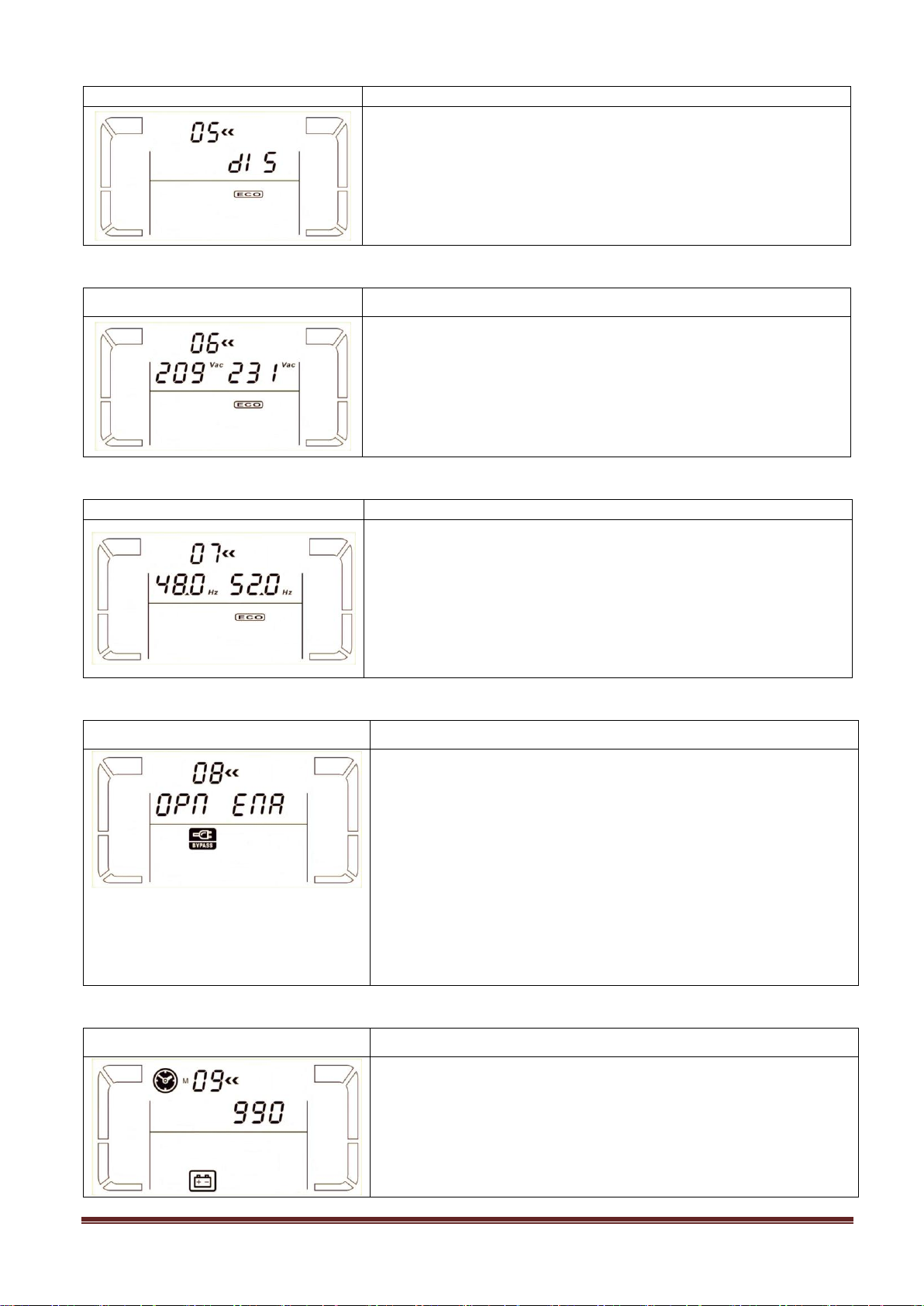
05: ECO mode enable/disable
Interface
Setting
Parameter 3: Enable or disable ECO function. You may choose
following two options:
DIS: disable ECO function
ENA: enable ECO function
If ECO function is disabled, voltage range and frequency range for
ECO mode still can be set, but it is meaningless unless the ECO
function is enabled.
Interface
Setting
Parameter 2: Low voltage point in ECO mode. The setting range
is from 5% to 10% of the nominal voltage.
Parameter 3: High voltage point in ECO mode. The setting range
is from 5% to 10% of the nominal voltage.
Interface
Setting
Parameter 2: Set low voltage point for ECO mode.
50 Hz system: Setting range is from 46.0Hz to 48.0Hz.
60 Hz system: Setting range is from 56.0Hz to 58.0Hz.
The default value is 48.0Hz/58.0Hz.
Parameter 3: Set high voltage point for ECO mode.
50 Hz: Setting range is from 52.0Hz to 54.0 Hz.
60 Hz: Setting range is from 62.0Hz to 64.0Hz.
The default value is 52.0Hz/62.0Hz.
Interface
Setting
Parameter 2:
OPN: Bypass allowed. When selected, UPS will run at Bypass
mode depending on bypass enabled/disabled setting.
FBD: Bypass not allowed. When selected, it’s not allowed for
running in Bypass mode under any situations.
Parameter 3:
ENA: Bypass enabled. When selected, Bypass mode is activated.
DIS: Bypass disabled. When selected, automatic bypass is
acceptable, but manual bypass is not allowed. Manual bypass
means users manually operate UPS for Bypass mode. For
example, pressing OFF button in AC mode to turn into Bypass
mode.
Interface
Setting
Parameter 3:
000~999: Set the maximum backup time from 0min to 999min.
UPS will shut down to protect battery after backup time arrives.
The default value is 990min.
DIS: Disable battery discharge protection and backup time will
depend on battery capacity.
06: Voltage range for ECO mode
07: Frequency range for ECO mode
08: Bypass mode setting
09: Battery backup time setting
www.powershield.com.au 20
Page 22
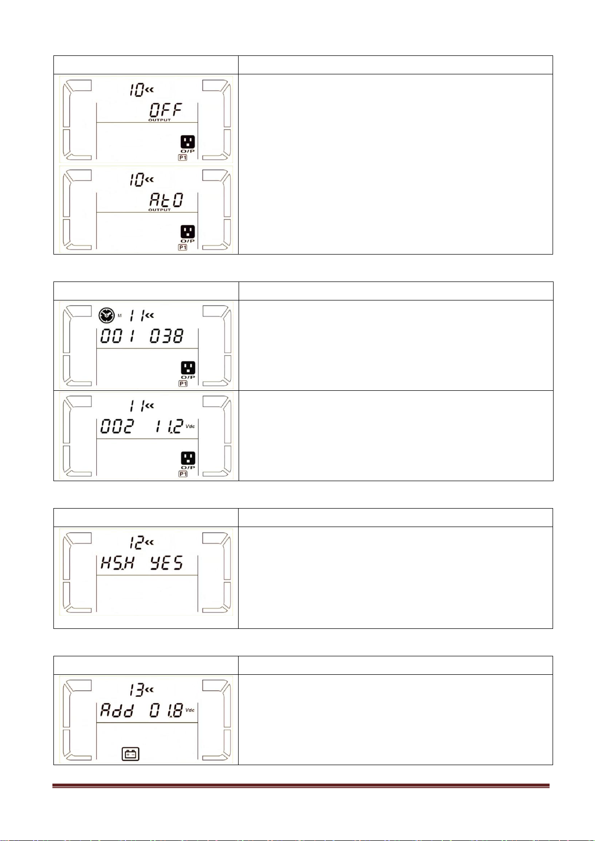
10: Programmable output setting
Interface
Setting
Parameter 3: Set programmable output. You may choose the
following three options:
ON: Programmable output is manually switched on timelessly.
OFF: Programmable output is manually switched off. However, if
UPS restarts, this setting will automatically go to “ATO” status.
ATO: Programmable output is automatically turned on or cut off
according to battery or load status. When the battery voltage is
lower than the setting point, or shutdown time arrives, the
programmable output will be cut off automatically. After the utility
is recovering, the output will turn on automatically. If overload
happens, the programmable output also will be cut off
automatically. If it happens 3 times, the programmable output will
be cut off until it is manually switched on.
Interface
Setting
Parameter 2: 001.
Set shutdown time for programmable output.
Parameter 3: Shutdown time in minutes.
Setting range is from 0 to 300. When shutdown time arrives, the
programmable output terminal will be cut off. The default value is
30 minutes.
Parameter 2: 002
Set shutdown voltage for programmable output.
Parameter 3: Shutdown voltage in V.
Setting range is from 11.2 to 13.6. If the battery voltage is less
than the setting point, the programmable output will be cut off.
The default value is 11.2V.
Interface
Setting
Parameter 2: HS.H
Enable or disable Hot standby function. You may choose following
two options in Parameter 3:
YES: Hot standby function is enabled. It means that the current
UPS is set to host of the hot standby function, and it will restart
after AC recovery even without battery connected.
NO: Hot standby function is disabled. The UPS is running at
normal mode and can’t restart without battery
Interface
Setting
Parameter 2: Select “Add” or “Sub” function to adjust battery
voltage to real figure.
Parameter 3: the voltage range is from 0V to 5.7V, the default
value is 0V.
11: Shutdown point for programmable output
12: Hot standby function enable/disable
13: Battery voltage adjustment
www.powershield.com.au 21
Page 23
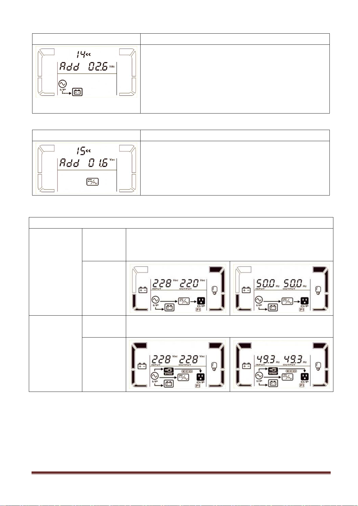
14: Charger voltage adjustment
Interface
Setting
Parameter 2: you may choose Add or Sub to adjust charger
voltage
Parameter 3: the voltage range is from 0V to 9.9V, the default
value is 0V.
NOTE:
*Before making voltage adjustment, be sure to disconnect all
batteries first to get the accurate charger voltage.
*We strongly suggest to use the default value (0). Any
modification should be suitable to battery specifications.
Interface
Setting
Parameter 2: you may choose Add or Sub to adjust inverter
voltage
Parameter 3: the voltage range is from 0V to 6.4V, the default
value is 0V.
Operating mode/status
AC mode
Description
When the input voltage is within acceptable range, UPS will provide pure
and stable AC power to output. The UPS will also charge the battery at
AC mode.
LCD display
ECO mode
Description
When the input voltage is within voltage regulation range and ECO mode
is enabled, UPS will bypass voltage to output for energy saving.
LCD display
15: Output voltage adjustment
3-8. Operating Mode/Status Description
www.powershield.com.au 22
Page 24
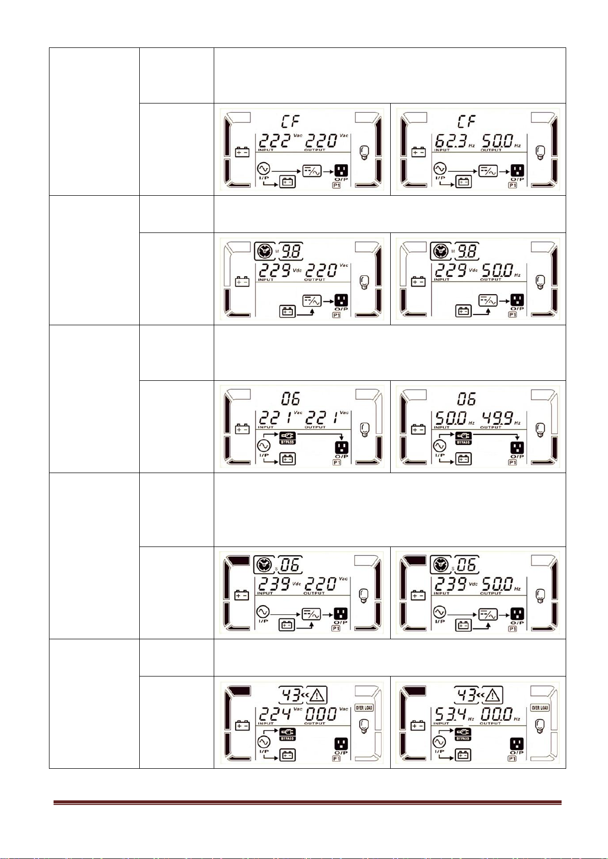
CVCF mode
Description
When input frequency is within 46 to 64Hz, the UPS can be set at a
constant output frequency, 50 Hz or 60 Hz. The UPS will still charge
battery under this mode.
LCD display
Battery mode
Description
When the input voltage is beyond the acceptable range or power failure,
UPS will backup power from battery and alarm will beep every 4 seconds.
LCD display
Bypass mode
Description
When input voltage is within acceptable range and bypass is enabled,
turn off the UPS and it will enter Bypass mode. Alarm beeps every two
minutes.
LCD display
Battery Test
Description
When UPS is in AC mode or CVCF mode, press “Test” key for more than
0.5s. Then the UPS will beep once and start “Battery Test”. The line
between I/P and inverter icons will blink to remind users. This operation
is used to check the battery status.
LCD display
Fault status
Description
When UPS has fault happened, it will display fault messages in LCD
panel.
LCD display
www.powershield.com.au 23
Page 25
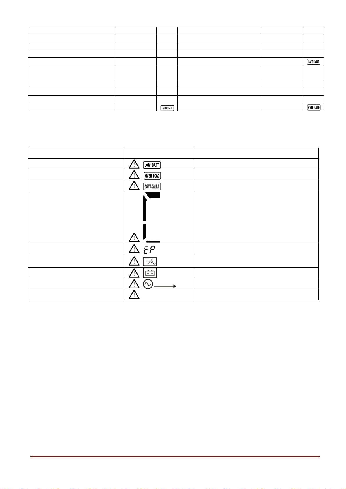
3-9. Fault Code
Fault event
Fault code
Icon
Fault event
Fault code
Icon
Bus start failure
01
None
Negative power fault
1A
None
Bus over
02
None
Battery SCR short circuited
21
None
Bus under
03
None
Inverter relay short circuited
24
None
Bus unbalance
04
None
Battery voltage loss
28
Bus short circuited
05
None
Parallel communication
failure
35
None
Inverter soft start failure
11
None
Output circuit circuited
36
None
High Inverter voltage
12
None
Over temperature
41
None
Low Inverter voltage
13
None
CPU communication failure
42
None
Inverter output short circuited
14
Overload
43
Warning
Icon (flashing)
Alarm
Battery low
Beeping every second
Overload
Beeping twice every second
Battery unconnected
Beeping every second
Over charge
Beeping every second
EPO enable
Beeping every second
Fan failure/Over temperature
Beeping every second
Charger failure
Beeping every second
I/P fuse broken
Beeping every second
Overload 3 times in 30min
Beeping every second
3-10. Warning Indicator
www.powershield.com.au 24
Page 26
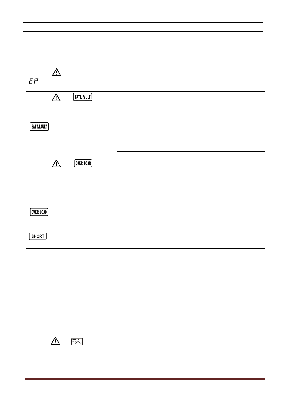
4. Trouble Shooting
Symptom
Possible cause
Remedy
No indication and alarm in the front
display panel even though the mains is
normal.
The AC input power is not
connected well.
Check if input cable firmly
connected to the mains.
The icon and the warning code
flash on LCD display and alarm
beeps every second.
EPO function is enabled.
Set the circuit in closed
position to disable EPO
function.
The icon and flash on
LCD display and alarm beeps every
second.
The external or internal
battery is incorrectly
connected.
Check if all batteries are
connected well.
Fault code is shown as 28, the icon
lights on LCD display, and
alarm beeps continuously.
Battery voltage is too low or
the charger is fault.
Contact your dealer.
The icon and flash on
LCD display and alarm beeps twice
every second.
UPS is overload.
Remove excess loads from UPS
output.
UPS is overloaded. Devices
connected to the UPS are fed
directly by the electrical
network via the Bypass.
Remove excess loads from UPS
output.
After repetitive overloads, the
UPS is locked in the Bypass
mode. Connected devices are
fed directly by the mains.
Remove excess loads from UPS
output first. Then shut down
the UPS and restart it.
Fault code is shown as 43. The icon
lights on LCD display and
alarm beeps continuously.
UPS is overload too long and
becomes fault. Then UPS shut
down automatically.
Remove excess loads from UPS
output and restart it.
Fault code is shown as 14, the icon
lights on LCD display, and
alarm beeps continuously.
The UPS shut down
automatically because short
circuit occurs on the UPS
output.
Check output wiring and if
connected devices are in short
circuit status.
Fault code is shown as 1, 2, 3, 4, 5, 11,
12, 13, 1A, 21, 24, 35, 36, 41 or 42 on
LCD display and alarm beeps
continuously.
A UPS internal fault has
occurred. There are two
possible results:
1. The load is still supplied, but
directly from AC power via
bypass.
2. The load is no longer
supplied by power.
Contact your dealer
Battery backup time is shorter than
nominal value
Batteries are not fully charged
Charge the batteries for at
least 7 hours and then check
capacity. If the problem still
persists, consult your dealer.
Batteries defect
Contact your dealer to replace
the battery.
The icon and flash on LCD
display and alarm beeps every second.
Fan is locked or not working;
or the UPS temperature is too
high.
Check fans and notify dealer.
If the UPS system does not operate correctly, please solve the problem by using the table below.
www.powershield.com.au 25
Page 27

5. Service
WARRANTY CONDITION:
The standard warranty is TWO (2) years from the date of purchase. The standard PowerShield procedure is
to replace the original unit with a factory refurbished unit. PowerShield will ship the replacement unit once
the defective unit has been received by the service department, or cross ship upon the receipt of a valid
credit card number. The customer pays for shipping the defective unit to PowerShield. PowerShield pays
ground freight transportation costs to shipthe replacement to the customer within Australian capital cities
metro areas only.
WARRANTY SEVICE PROCESS :
1. Review the problems discussed in the troubleshoot section of this manual to eliminate common
problems.
2. Verify that no input/output circuit breaker are tripped. A tripped circuit breaker is the most common
problem.
3. If the problem still persists, please call 1300-305-393 for technical support or fill in the form in
PowerShield web page for on line technical support.
Following details are needed for warranty claims.
Model number
Serial number
The date of purchase
4. Be prepare to troubleshoot the problem over the phone with PowerShield technical support.
5. If technical support found that the product is defective, then the technical support will issue a Return
Material Authorization Number ( RMA # )
6. If the unit is under warranty, repair is free. If not there is a repair charge.
7. Pack the unit in its original packaging. Pack properly to avoid damage during transit. Damage sustained
in transit is not covered under warranty.
8. Mark the RMA # on the outside of the package.
9. Return the defective unit by insured, prepaid carrier to the address given to you by Technical support.
6. Contacting PowerShield
Refer to the information provided at PowerShield internet site:
www.powershield.com.au
Or
Phone 1300 305 393
www.powershield.com.au 26
Page 28
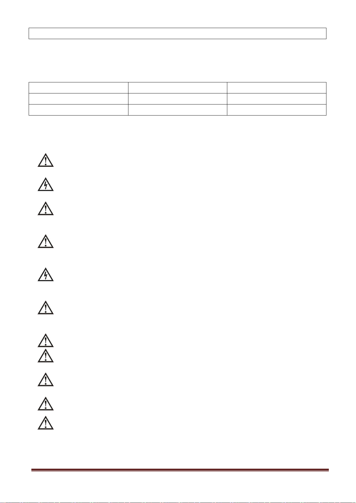
7. Storage and Maintenance
Storage Temperature
Recharge Frequency
Charging Duration
-25°C - 40°C
Every 3 months
1-2 hours
40°C - 45°C
Every 2 months
1-2 hours
7-1. Storage
Before storing, charge the UPS at least 7 hours. Store the UPS covered and upright in a cool, dry
location. During storage, recharge the battery in accordance with the following table:
7-2. Maintenance
The UPS system operates with hazardous voltages. Repairs may be carried out only by qualified
maintenance personnel.
Even after the unit is disconnected from the mains, components inside the UPS system are still
connected to the battery packs which are potentially dangerous.
Before carrying out any kind of service and/or maintenance, disconnect the batteries and verify that
no current is present and no hazardous voltage exists in the terminals of high capability capacitor such as
BUS-capacitors.
Only persons are adequately familiar with batteries and with the required precautionary measures
may replace batteries and supervise operations. Unauthorized persons must be kept well away from the
batteries.
Verify that no voltage between the battery terminals and the ground is present before maintenance
or repair. In this product, the battery circuit is not isolated from the input voltage. Hazardous voltages may
occur between the battery terminals and the ground.
Batteries may cause electric shock and have a high short-circuit current. Please remove all
wristwatches, rings and other metal personal objects before maintenance or repair, and only use tools
with insulated grips and handles for maintaining or repairing.
When replace the batteries, install the same number and same type of batteries.
Do not attempt to dispose of batteries by burning them. This could cause battery explosion. The
batteries must be rightly deposed according to local regulation.
Do not open or destroy batteries. Escaping electrolyte can cause injury to the skin and eyes. It may
be toxic.
Please replace the fuse only with the same type and amperage in order to avoid fire hazards.
Do not disassemble the UPS system.
www.powershield.com.au 27
Page 29
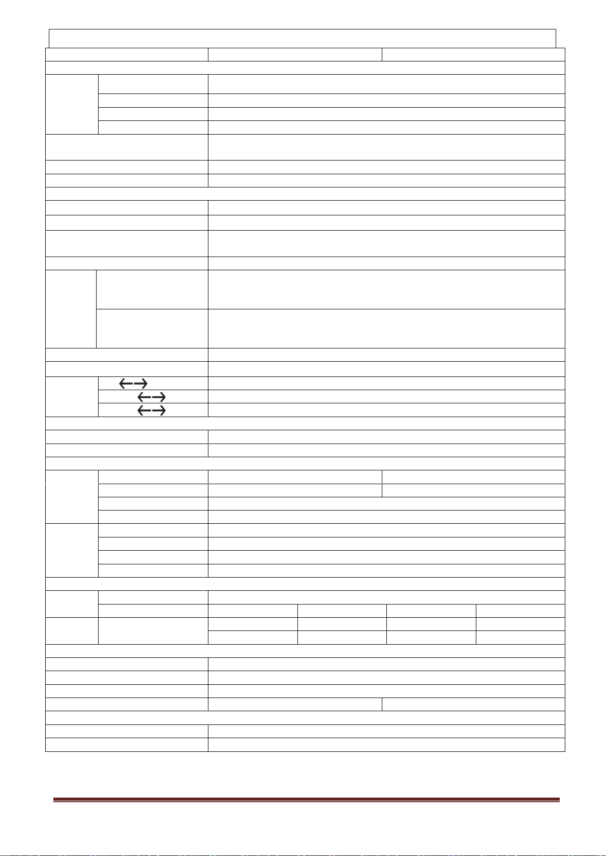
8. Specifications
CAPACITY*
6000 VA / 4800 W
10000 VA / 8000 W
INPUT
Voltage
Range
Low Line Loss
110 VAC ± 3 % at 50% Load; 176 VAC ± 3 % at 100% Load
Low Line Comeback
Low Line Loss Voltage + 10V
High Line Loss
300 VAC ± 3 %
High Line Comeback
High Line Loss Voltage - 10V
Frequency Range
46Hz ~ 54 Hz @ 50Hz system
56Hz ~ 64 Hz @ 60Hz system
Phase
Single phase with ground
Power Factor
≧ 0.99 at 100% Load
OUTPUT
Output voltage
208/220/230/240VAC
AC Voltage Regulation
± 1%
Frequency Range
(Synchronized Range)
46Hz ~ 54 Hz @ 50Hz system
56Hz ~ 64 Hz @ 60Hz system
Frequency Range (Batt. Mode)
50 Hz ± 0.1 Hz or 60Hz ± 0.1 Hz
Overload
AC mode
100%~110%: 10min
110%~130%: 1min
>130% : 1sec
Battery mode
100%~110%: 30sec
110%~130%: 10sec
>130% : 1sec
Current Crest Ratio
3:1 max
Harmonic Distortion
≦ 3 % @ 100% Linear Load; ≦ 6 % @ 100% Non-linear Load
Transfer
Time
Line Battery
0 ms
Inverter Bypass
0 ms
Inverter ECO
<10 ms
EFFICIENCY
AC mode
> 89%
Battery Mode
> 88%
BATTERY
Standard
Model
Type & Numbers
12 V / 9 Ah x 20
12 V / 9 Ah x 20
Recharge Time
7 hours recover to 90% capacity
9 hours recover to 90% capacity
Charging Current
1.0 A ± 10% (max.)
Charging Voltage
14.4 V ± 1%
Long-run
Model
Type
Depending on applications
Numbers
18 - 20
Charging Current
4.0 A ± 10% (max.)
Charging Voltage
14.4 V ± 1%
PHYSICAL
Outline
Dimension, D X W X H
592 X 250 X 576
Net Weight (kgs)
81
25
83
27
Packaging
Dimension, D X W X H
Net Weight (kgs)
700 X 385 X 815
690 X 370 X670
700 X 385 X 815
690 X370 X670
88
28
90
30
ENVIRONMENT
Operation Temperature
0 ~ 40°C (the battery life will down when > 25°C)
Operation Humidity
<95 % and non-condensing
Operation Altitude**
<1000m
Acoustic Noise Level
Less than 55dB @ 1 Meter
Less than 58dB @ 1 Meter
MANAGEMENT
Smart RS-232 or USB
Supports Windows® 98/2000/2003/XP/Vista/2008
Optional SNMP
Power management from SNMP manager and web browser
* Derate capacity to 60% of capacity in CVCF mode and to 90% when the output voltage is adjusted to 208VAC.
**If the UPS is installed or used in a place where the altitude is above than 1000m, the output power must be derated one percent per
100m.***Product specifications are subject to change without further notice.
www.powershield.com.au 28
Page 30

37-100286-01G
 Loading...