

Page 1
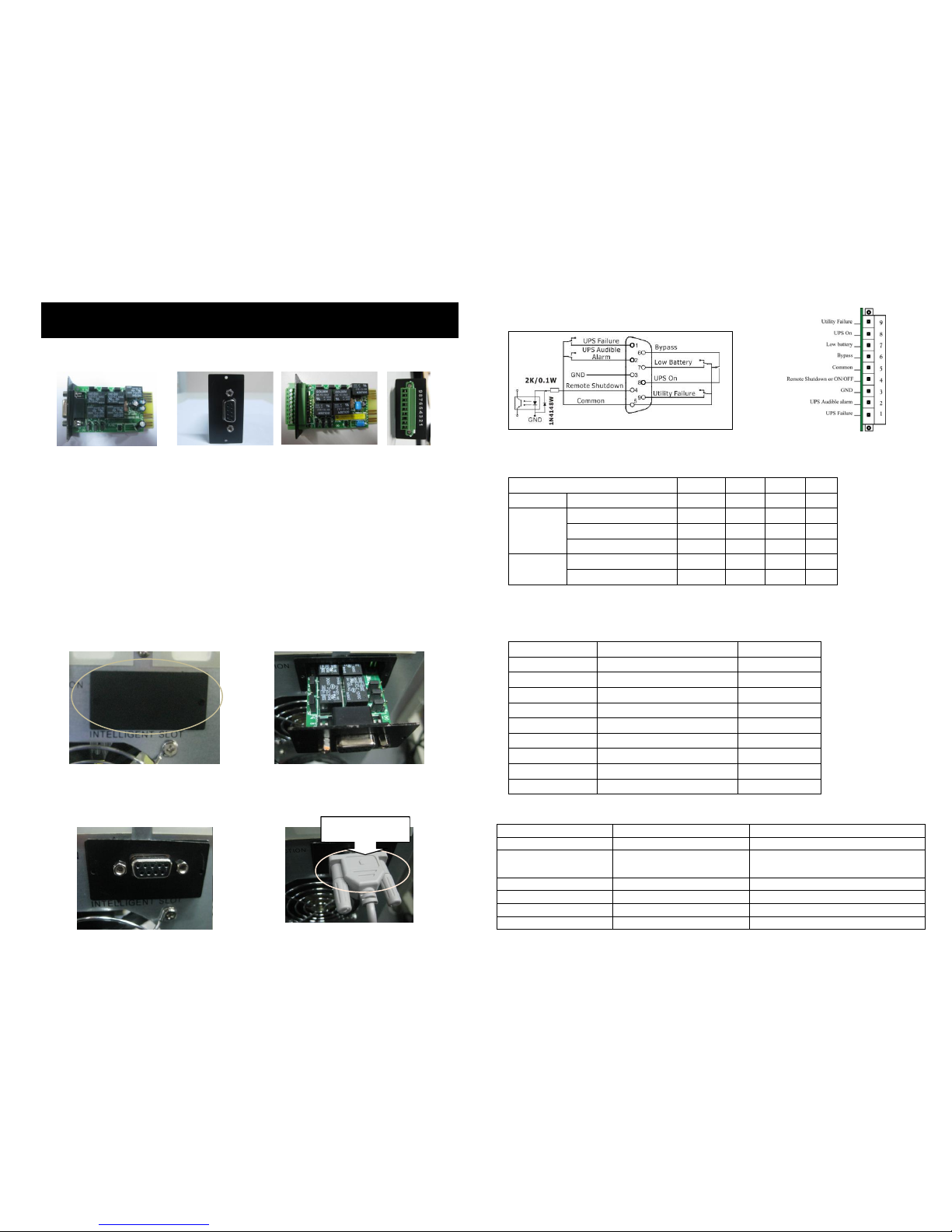
1. Product Outlook
DB-9 port 9-pin port
Top View Side View Top View Side View
2. Product Introduction
The PSAS400 communication card provides contact closures for remote monitoring of your
UPS. To meet different application requirements the PSAS400 card is capable of selecting the
status of the dry-contact signal (active close or active open) by setting jumper. The suitable
applications are listed below:
IBM Server, Personal PC & Workstations equipments
Auto-controlled industrial equipment & communication applications
3. Installation
Step 1: Remove cover of Intelligent Slot
on the rear panel of the UPS.
Step 2: Insert PSAS400 card into
Intelligent Slot.
Step 3: The cover of PSAS400 should
attach close to the rear panel. Using
screwdriver, secure the AS400 to the
UPS chassis with 2 screws.
Step 4: Use the 9-pin communication cable
to connect UPS and equipment to implement
the remote monitoring and control.
4. Specifications
Internal circuit of DB-9 port
RS-232 port 9-pin port
Electric Parameter of DB-9 port
Parameter
Symbol
Max.
Min.
Unit
Resistor*
DC Current
IR 6 1
mA
Diode
Reverse Voltage
VR 6 -
V
Forward Current
IF
50 - mA
Peak Forward Current
IF (Peak) 1 -
A
Relay
DC Voltage
VDC
24 - V
DC Current
IDC
1.0 - A
Note: It’s required to retain the DC current lower than 6mA. Otherwise, it’s necessary to add one resistor
within DC current limitation in the serial loop of Remote Shutdown. (e.g. 2K resistor with at least 0.1W
rating power). Refer to diagrams in Application.
Pin Assignment
Pin Assignment
Function
I/O
Pin 1
UPS Failure
O/P
Pin 2
UPS Audible Alarm
O/P
Pin 3
GND (Common for Pin 4)
Power Ground
Pin 4
Remote Shutdown
I/P
Pin 5
Common for Relays
Power Supply
Pin 6
Bypass Active
O/P
Pin 7
Low Battery
O/P
Pin 8
UPS On
O/P
Pin 9
Utility Failure
O/P
P.S. The shutdown pin (pin4 & pin3) only accepts 3-10s high level signal to perform the UPS shutdown.
Function Description
AC Status
AO Status
Reason
Pin 1 & Pin 5 connected
Pin 1 & Pin 5 disconnected
UPS failure
Pin 2 & Pin 5 connected
Pin 2 & Pin 5 disconnected
UPS failure, utility failure, low
battery, bypass active
Pin 6 & Pin 5 connected
Pin 6 & Pin 5 disconnected
Bypass active
Pin 7 & Pin 5 connected
Pin 7 & Pin 5 disconnected
Battery voltage is low
Pin 8 & Pin 5 connected
Pin 8 & Pin 5 disconnected
UPS is in inverter mode
Pin 9 & Pin 5 connected
Pin 9 & Pin 5 disconnected
Utility failure
PowerShield AS400 (PSAS400) Card Remote Shutdown Quick Guide
V. 3.0
9 pin com. cable
Page 2
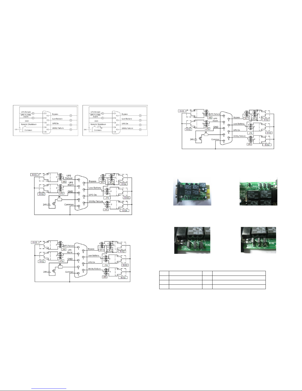
Application:
Below shows the circuit of a basic application to implement monitoring and control.
User Interface for 12 V User Interface for 24 V
5. Internal Logical Connection
IC controller of the card controls actions of 5 relays depending on the UPS status.
Active-Close(A.C) terminal and Active-Open(A.O) terminal of each relay connect to pin 3 and pin
1 of a 3-pin connector respectively. The pin 2 of the 3-pin connector connects to the signal pin of
the DB9 interface connector. The 2-pin jumper can be plugged to the 3-pin connector to either
short-circuit Pin1 & Pin2(A.C) or short-circuit Pin3 & Pin2(A.O).
Fig 1 Pin definition and internal logical connection
Accordingly, if pin1 short-circuits with pin2 via the jumper, the status of dry contact signal will be
ACTIVE CLOSE, refer to Fig 2. When the signal is active, the signal pin on the DB9 connector will
connect with the common pin (pin5) via the relay.
Fig 2 Connection for ACTIVE CLOSE
If Pin3 short-circuit with Pin2(A.O) via the jumper, the status of dry contact signal will be
ACTIVE OPEN, refer to Fig 3. When the signal is active, the signal pin on the DB9 connector will
disconnect with the common pin (pin5) via the relay.
Fig. 3 Connection for ACTIVE OPEN
6 Jumper Set-up
The 3-pin connectors can be easily found
just near to the relay. Refer to Fig. 4.
There are AC and AO white silk printings of
the connector as shown in Fig. 5 to indicate
pin1&2 in A.C and pin2&3 in A.O.
Fig.4 PSAS400 card
Fig. 5 AO and AC silk printings
indicates each 3-pin connector status
To achieve ACTIVE CLOSE dry-contact
signal, the jumper should connect the 2
pins(Pin1&2) as shown in Fig. 6.
To achieve ACTIVE OPEN dry-contact signal,
the jumper should connect the middle pin
and the pin3 as shown in Fig. 7
Fig. 6 Jumper setting for ACTIVE
CLOSE
Fig. 7 Jumper setting for ACTIVE
OPEN
Jumper function description
JP
Description
JP
Description
1
UPS alarm (DB9.P2)
4
Low battery(DB9.P7)
2
UPS on(DB9.P8)
5
Utility failure(DB9.P9)
3
Bypass(DB9.P6)
6
UPS failure(DB9.P1)
 Loading...