

Page 1

PowerShield 8
Installation Manual
Page 2

___________________________________________________________________________________________________________
Part Number 6300-095D Page 2 of 43
Table of Contents
1 Glossary ........................................................................................................................................................................... 4
2 Introduction ...................................................................................................................................................................... 5
3 Installation Quick Guide ................................................................................................................................................... 6
4 The PowerShield 8 Battery Monitoring System ................................................................................................................ 8
4.2 Controller ............................................................................................................................................................... 10
4.2.1 Power Supply ................................................................................................................................................ 10
4.2.2 Front and Rear Panels .................................................................................................................................. 10
4.2.3 Hub Ports and BBus Communication ............................................................................................................ 11
4.2.4 Installation ..................................................................................................................................................... 11
4.3 Hub ........................................................................................................................................................................ 12
4.4 mSensor ................................................................................................................................................................ 13
5 Installation ...................................................................................................................................................................... 14
5.1 Install Controller and Power-up ............................................................................................................................. 14
5.2 Number Blocks ...................................................................................................................................................... 14
5.3 Block Terminal Tags .............................................................................................................................................. 15
5.4 Mounting Rail for Hubs and mSensors .................................................................................................................. 15
5.5 mSensor Power Leads .......................................................................................................................................... 16
5.6 Connect mSensors to Blocks ................................................................................................................................. 17
5.7 Install Hub .............................................................................................................................................................. 17
5.8 Connect BBus Cables............................................................................................................................................ 18
5.9 Install Current Transducer ..................................................................................................................................... 19
5.10 Connect Ambient Temperature Probe(s) ............................................................................................................. 20
5.11 Confirmation and Configuration ........................................................................................................................... 20
Appendix 1 – Controller Panels ......................................................................................................................................... 21
Front Panel .................................................................................................................................................................. 21
Rear Panel ................................................................................................................................................................... 21
Appendix 2 – LED Behaviour ............................................................................................................................................ 23
PowerShield Controller LEDs ...................................................................................................................................... 23
mSensor and Hub LEDs .............................................................................................................................................. 24
Appendix 3 – Controller LCD ............................................................................................................................................. 25
Appendix 4 – Communication Options .............................................................................................................................. 26
RS-485 ........................................................................................................................................................................ 26
Cabling & Termination ................................................................................................................................................. 26
Appendix 5 – Relays and Auxiliary Inputs ......................................................................................................................... 27
Relays.......................................................................................................................................................................... 27
Auxiliary Inputs ............................................................................................................................................................ 27
Appendix 6 – mSensor Power Lead Connection ............................................................................................................... 28
Dual mSensor and Blocks with 2 Terminals ................................................................................................................ 28
Single mSensor and Block with 2 Terminals ................................................................................................................ 29
Dual mSensor and Blocks with 4 Terminals ................................................................................................................ 30
Single mSensor and Block with 4 Terminals ................................................................................................................ 31
mSensor Power Leads with Block Temperature .......................................................................................................... 32
mSensor Power Leads without Block Temperature ..................................................................................................... 32
Appendix 7 – 4-Wire / Kelvin Connection .......................................................................................................................... 33
Resistance ................................................................................................................................................................... 33
Page 3

___________________________________________________________________________________________________________
Part Number 6300-095D Page 3 of 43
2-Wire Resistance Measurement ................................................................................................................................ 33
4-Wire/Kelvin Resistance Measurement ...................................................................................................................... 34
Appendix 8 – DC Model Controller Wiring ......................................................................................................................... 35
DC Model Plug ............................................................................................................................................................ 35
Appendix 9 – Controller Specifications .............................................................................................................................. 37
Appendix 10 – Hub Specifications ..................................................................................................................................... 38
Appendix 11 – mSensor Specifications ............................................................................................................................. 39
Appendix 12 - PowerShield 8 Installation Forms ............................................................................................................... 40
6300-107 Facility Information Form (FIF) .................................................................................................................... 40
6300-108 PowerShield 8 Controller Information Form (CIF)........................................................................................ 41
6300-109 PowerShield 8 String Information Form (SIF) .............................................................................................. 42
6300-110 PowerShield 8 Block Mapping Form (BMF) ................................................................................................. 43
Page 4

___________________________________________________________________________________________________________
Part Number 6300-095D Page 4 of 43
1 Glossary
Cell
The basic electrochemical unit that can receive, store, and deliver electrical
energy.
Block
One or more cells in a container also known as a battery.
The terms block and jar are interchangeable.
For this manual the term has been standardised as block to avoid using the
somewhat unwieldy convention of "block/jar" throughout.
String
Two or more blocks connected in series.
Battery Bank
A complete system of parallel connected strings.
PowerShield Controller
Data logger that periodically communicates with PowerShield Hubs and
PowerShield mSensors to obtain system measurements.
PowerShield mSensor
A remote sensor that is connected to the blocks.
It periodically measures the block voltage, ohmic value and temperature.
PowerShield Hub
A remote sensor that can be used to measure string current and ambient
temperature of the battery bank.
mSensors can be connected to it so that they share the same
communication cable from the PowerShield Controller.
BBus
A daisy chain communication bus used between the PowerShield Controller
and PowerShield Hubs or PowerShield mSensors.
Page 5

___________________________________________________________________________________________________________
Part Number 6300-095D Page 5 of 43
2 Introduction
This manual is intended for use with the PowerShield 8 battery monitoring system that uses the PowerShield Controller
data logger, PowerShield mSensor battery sensors and the PowerShield Hub. This manual describes the installation of
the system hardware.
About this manual
PowerShield 8 Installation Manual
Part Number 6300-095D
14 Nov 2018
The information contained in this manual is copyright and is not to be reproduced without the written authority of
PowerShield Ltd.
PowerShield Limited
PO Box 102-190
NSMC
North Shore City 0745
New Zealand
PowerShield is committed to being responsible to take care of our environment. PowerShield products and packaging
contain materials that are highly recoverable and recyclable. Please consider recycling through proper channels at your
local packaging recycler and e-waste recycler.
Page 6
___________________________________________________________________________________________________________
Part Number 6300-095D Page 6 of 43
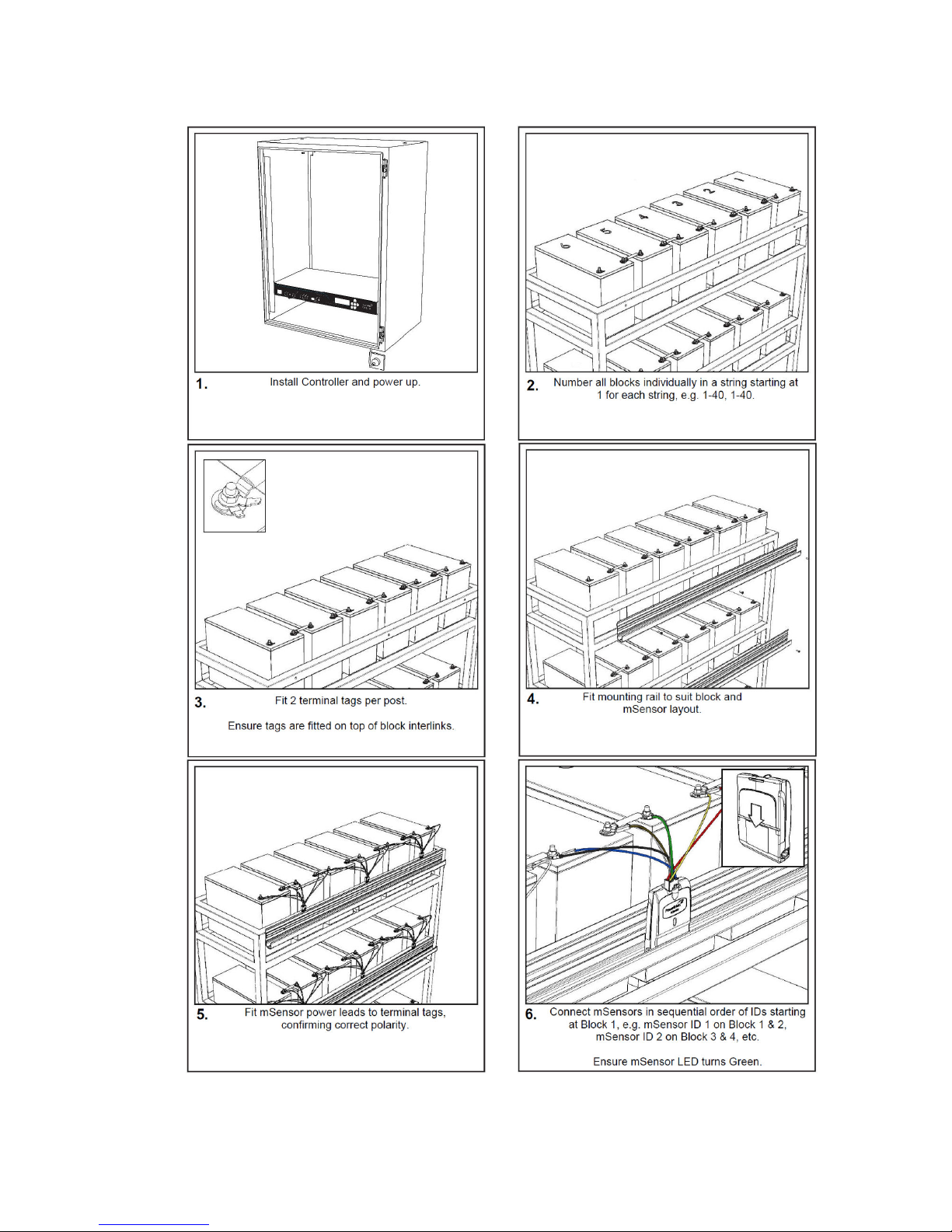
3 Installation Quick Guide
Page 7
___________________________________________________________________________________________________________
Part Number 6300-095D Page 7 of 43
Page 8

___________________________________________________________________________________________________________
Part Number 6300-095D Page 8 of 43
4 The PowerShield 8 Battery Monitoring System
The PowerShield 8 battery monitoring system is a permanent battery monitoring system that can monitor one or more
strings of blocks. Parameters measured include:
• DC & AC voltage of each block
• Ohmic value of each block
• Temperature of each block
• DC string voltage
• DC & AC string current
• Ambient temperature
• Ambient humidity
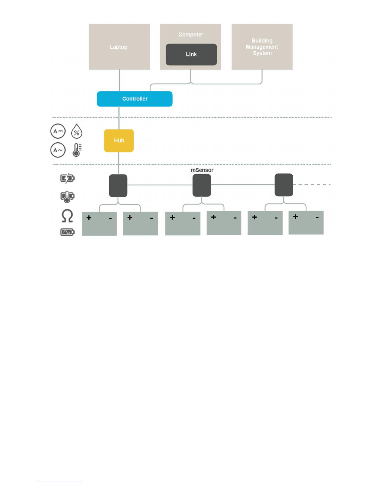
The diagram on the following page shows an overview of the system which consists of the following hardware:
• PowerShield Controller
• PowerShield Hubs
• PowerShield mSensors
• Current Transducers
• Ambient Temperature sensors
• Hub-to-BBus adaptors (where applicable)
The PowerShield Hub is used to connect external sensors for measuring string current and ambient temperature and has
an on board ambient humidity sensor. The PowerShield mSensor is used to monitor each block. The PowerShield
Controller periodically interrogates each Hub and mSensor and processes the data, logging the information into memory
at predefined intervals.
The distributed system architecture using local Hubs and mSensors installed at the battery bank, connected to the
PowerShield Controller using a single CAT5 cable, allows one PowerShield Controller to monitor multiple remote strings.
A single system can also monitor different voltage blocks and strings using appropriate mSensors.
PowerShield provides Link software for automated multi-site battery management.
Page 9
___________________________________________________________________________________________________________
Part Number 6300-095D Page 9 of 43
Page 10
___________________________________________________________________________________________________________
Part Number 6300-095D Page 10 of 43
4.2 Controller
The PowerShield Controller is supplied in a 1U high 19" rack case. The PowerShield Controller can be mounted in a
19" rack, on a wall, shelf, or similar using the mounting brackets provided. Ensure there is safe access to the rear
connector panel and cable tray.
4.2.1 Power Supply
The PowerShield Controller is available in AC input or DC input models.
The
AC input model has a standard 3-pin male IEC 60320 C14 appliance inlet.
The D
C input models have a male 3-pin input socket and are supplied with a mating female screw terminal plug.
• Both AC and DC models must be installed by a service person and connected to a socket outlet or fixed
wiring with a protective earth conductor or connector.
• A readily available disconnect device shall be incorporated in the building wiring or the socket outlet near
the PowerShield Controller that is readily accessible.
• The power source for the DC models must be fused with a circuit breaker of no greater than 20A rating.
The connection must be installed in a service access area.
• To ensure that the system operates during a power failure, it is recommended that the PowerShield
Controller is powered by a battery backed supply that has sufficient backup time.
4.2.2 Front and Rear Panels
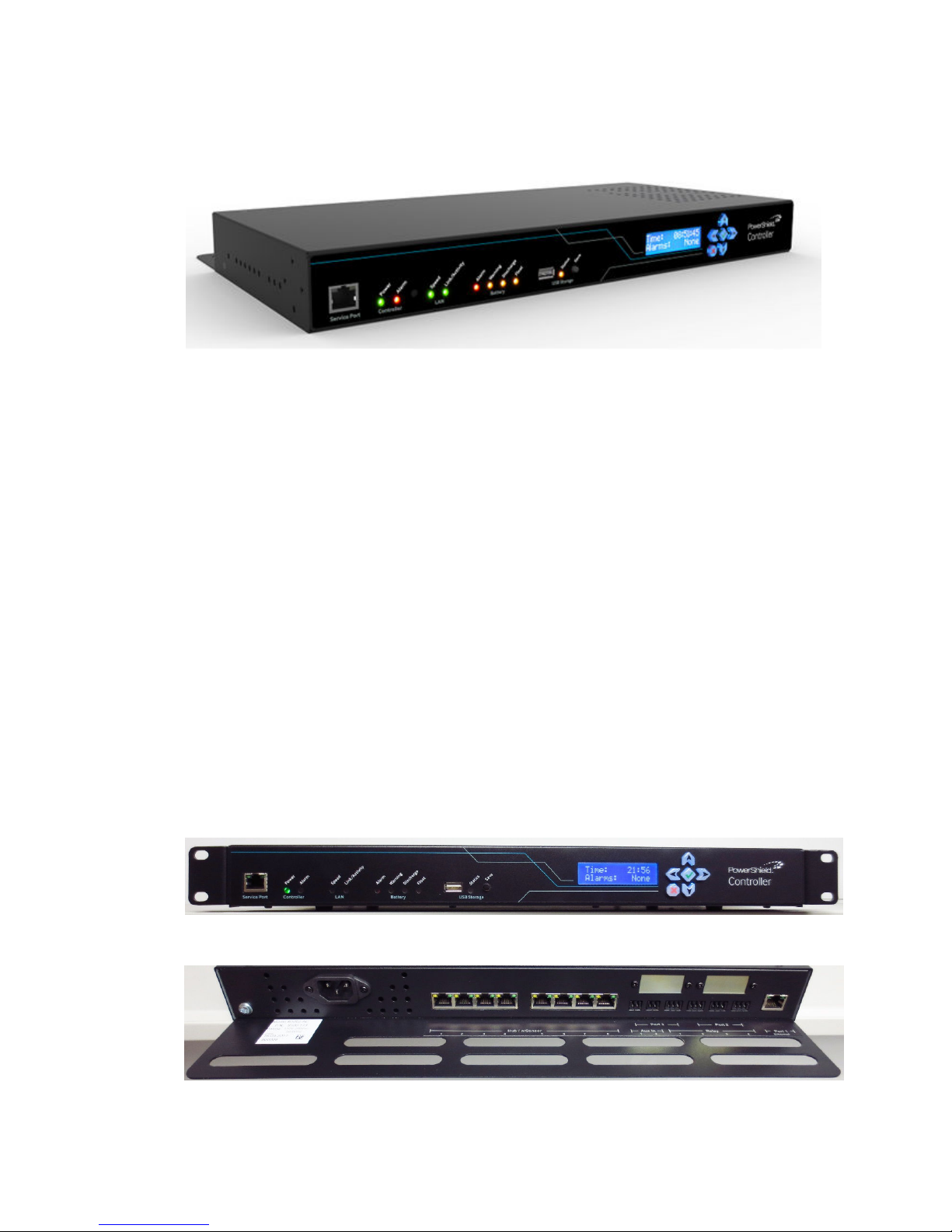
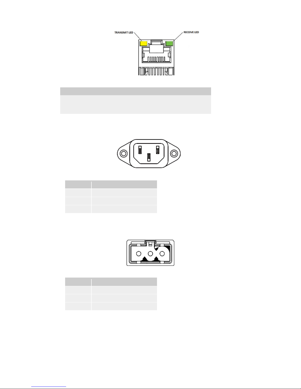
The front and rear panels of the PowerShield Controller are shown below.
Refer to Appendix 1 for a description of the front and rear panel features. Refer to Appendix 2 for a description of the
front panel LED behaviour.
PowerShield Controller Front Panel
PowerShield Controller Rear Panel
Page 11

___________________________________________________________________________________________________________
Part Number 6300-095D Page 11 of 43
4.2.3 Hub Ports and BBus Communication
The PowerShield Controller communicates with the PowerShield Hubs and PowerShield mSensors via the hub ports on
the rear panel of the Controller. The hub ports use the BBus daisy chain communication bus with the devices being
connected in series, one after another.
The hub port connectors are 8-pin RJ45 connectors. Standard CAT5 cabling is used to connect the PowerShield Hubs
to the PowerShield Controller via the RJ45 connectors on each device. The PowerShield Hub should be the first device
on each bus. The cable distance between the PowerShield Controller hub port and PowerShield Hub should not extend
more than 50m (165ft). Contact PowerShield if longer distances are required.
The PowerShield mSensors should be connected to the PowerShield Hub using 4-core BBus interconnect cable via the
4-pin Modular Jack connectors on each device. The total cable length between the PowerShield Hub and last
PowerShield mSensor, including the short interconnecting BBus cables between each device, should not extend more
than 25m (82ft). Contact PowerShield if longer distances are required.
Each PowerShield Controller hub port is capable of supporting 1 Hub and up to 32 mSensors. For strings with a large
number of blocks, additional mSensors will need to be used. These can be connected to spare Controller hub ports
using an adaptor available from PowerShield that converts the Controller hub port CAT5 cable to 4-core BBus
interconnect cable.
4.2.4 Installation
The PowerShield 8 battery monitoring system must be correctly installed and configured in order to obtain accurate
results. The installation of the system must be carried out only by suitably trained personnel. Installation must be in an
adequately ventilated environment or the warranty may be invalidated.
The PowerShield 8 battery monitoring system operates in a potentially hazardous environment making it imperative that
all installation personnel have adequate training and experience. The system must be installed in a Service Access
area.
Pay particular attention to the following points:
A) Elevated Operating Ambient Temperature – If installed in a closed or multi-unit rack assembly, the operating
ambient temperature of the rack environment may be greater than room ambient. Therefore, consideration
should be given to installing the equipment in an environment compatible with the maximum temperature
specified in Appendix 9 – PowerShield Controller Specifications.
B) Reduced Air Flow – Installation of the equipment in a rack should be such that the amount of air flow
required for safe operation of the equipment is not compromised.
C) Mechanical Loading – Mounting of the equipment in the rack should be such that a hazardous condition is
not achieved due to uneven mechanical loading.
D) Circuit Overloading – Consideration should be given to the connection of the equipment to the supply circuit
and the effect that overloading of the circuits might have on over-current protection and supply wiring.
Appropriate consideration of equipment nameplate ratings should be used when addressing this concern.
E) Reliable Earthing – Reliable earthing of rack-mounted equipment should be maintained. Particular attention
should be given to supply connections other than direct connections to the branch circuit (e.g. use of power
strips).
Page 12
___________________________________________________________________________________________________________
Part Number 6300-095D Page 12 of 43
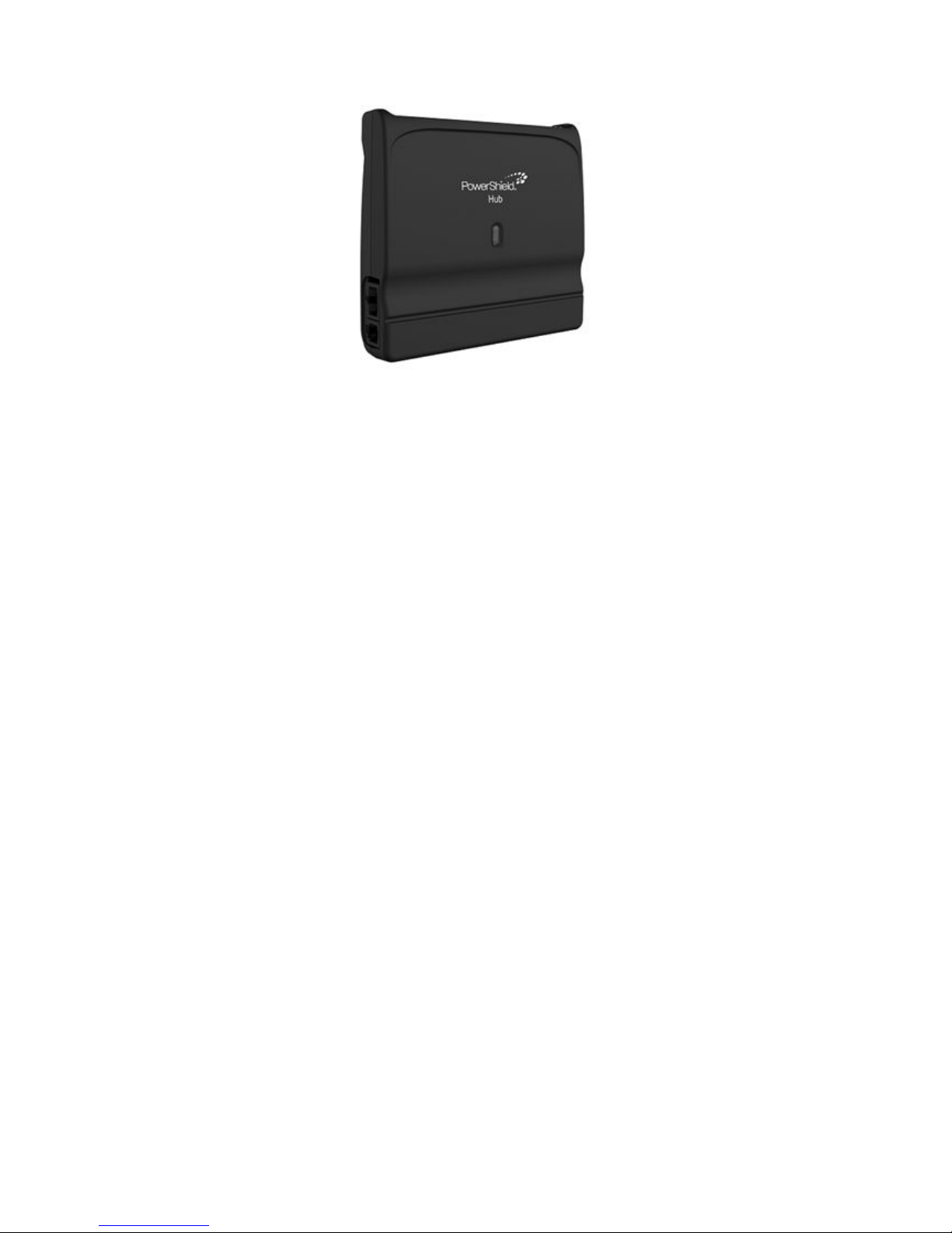
4.3 Hub
The PowerShield Hub is used to connect external sensors for measuring string current and ambient temperature and has
an on board ambient humidity sensor. Each Hub can read from one Current Transducer and up to two Ambient
Temperature probes. It also has two Dry Contact inputs that can be used to read the state of external devices.
The PowerShield Controller communicates with the Hubs via the Controller hub ports, connected using CAT5 cable. It
also supplies 24VDC power to the Hubs over this cable. Up to eight Hubs can be connected to a single PowerShield
Controller, 1 per Controller hub port. This allows up to eight strings to be monitored with one PowerShield Controller.
The Hub is also the BBus link between the PowerShield Controller and mSensors. The mSensors are connected to the
Hub using 4-core BBus interconnect cable.
Each Hub has a factory set ID number in the range 221 to 230. Hub ID 221 should be used for the first string and
subsequent sequentially numbered Hubs are used for multiple string systems (where applicable).
The LED on the Hub indicates Hub state. Refer to Appendix 2 for Hub LED behaviour.
Page 13
___________________________________________________________________________________________________________
Part Number 6300-095D Page 13 of 43
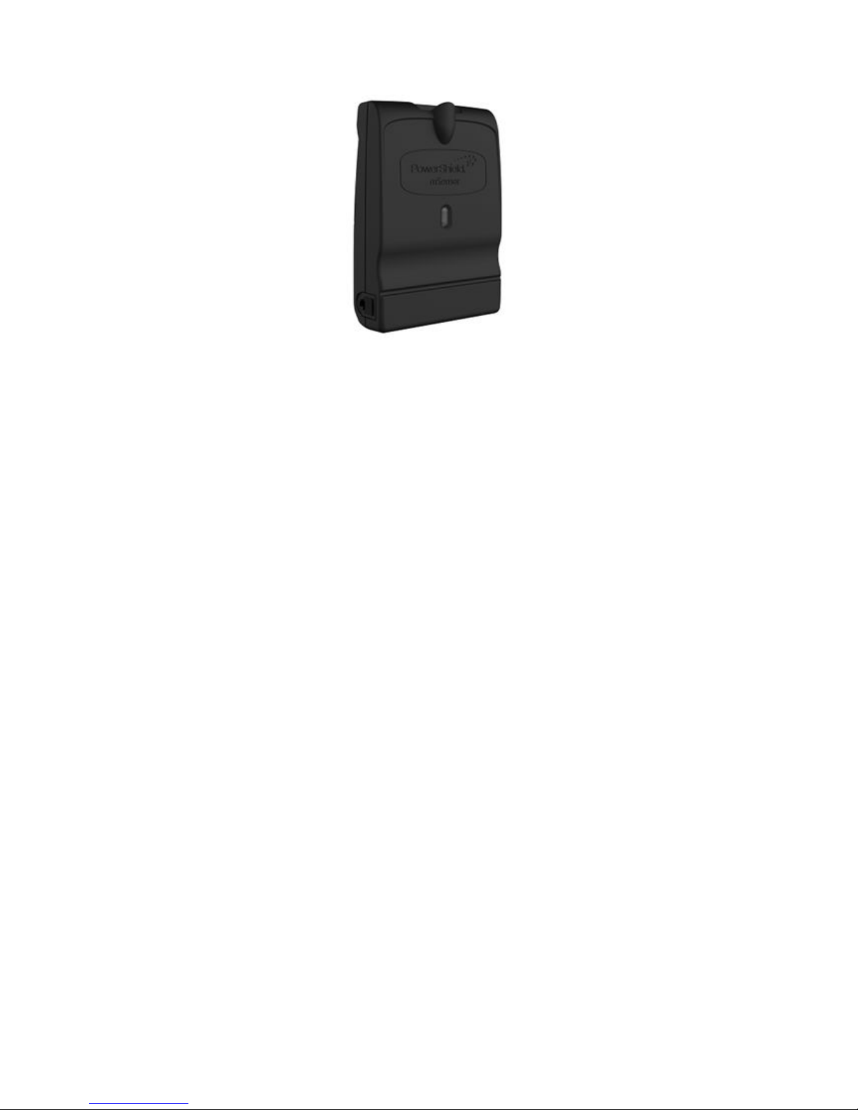
4.4 mSensor
The PowerShield mSensor connects to the blocks and periodically measures the block voltage, temperature and ohmic
value. Each mSensor is specific to the block voltage to which it will be fitted, e.g. 2V / 6V / 12V.
Dual and single mSensors are available. A dual mSensor is used to monitor a pair of blocks located one after another in
series. A single mSensor is used to monitor only one block. The single mSensor allows for installations containing
strings with uneven numbers of blocks or where physical layout makes pairing of blocks impossible. The label on the
mSensor will show whether it is single or dual.
Each mSensor has a factory set ID number. Dual mSensors are numbered with IDs in the range 1 to 200 while single
mSensors are numbered 201 to 220. For ease of mapping of mSensors to blocks and subsequent system configuration,
it is recommended to connect the mSensors to the blocks in sequential order of ID starting at ID 1. Each block in a string
must be uniquely identified with a sequential number starting at 1. For correct automatic mapping of mSensors to blocks,
the block numbering should start at the most positive block in the string. If single mSensors are used in a string, they
should also be installed in sequential order of ID starting at ID 201.
The PowerShield Controller communicates with the mSensors via the Controller hub ports using the BBus daisy chain
communication bus. The mSensors should be connected to the PowerShield Hub using 4-core BBus interconnect cable
via the 4-pin Modular Jack connectors on each device. If a Hub is not used, it is possible to connect the mSensors to the
PowerShield Controller using a Hub-to-BBus adaptor that converts the Controller hub port CAT5 cable to 4-core BBus
interconnect cable.
The LED on the mSensor indicates sensor state. Refer to Appendix 2 for mSensor LED behaviour.
Page 14
___________________________________________________________________________________________________________
Part Number 6300-095D Page 14 of 43
5 Installation
Complete the forms in Appendix 12 during the installation.
5.1 Install Controller and Power-up
The PowerShield Controller is supplied in a 1U high 19" rack case. Mount the PowerShield Controller securely into a 19"
rack (not supplied), wall, shelf, or similar using the mounting brackets provided. Ensure there is safe access to the rear
connector panel and cable tray.
When the PowerShield Controller is powered up, it will emit an audible alert and the green Power LED will light. Other
LEDs on the front panel may also light.
NOTE: Ensure the PowerShield Controller is unable to move when installed – cables and connections must not be
put under strain.
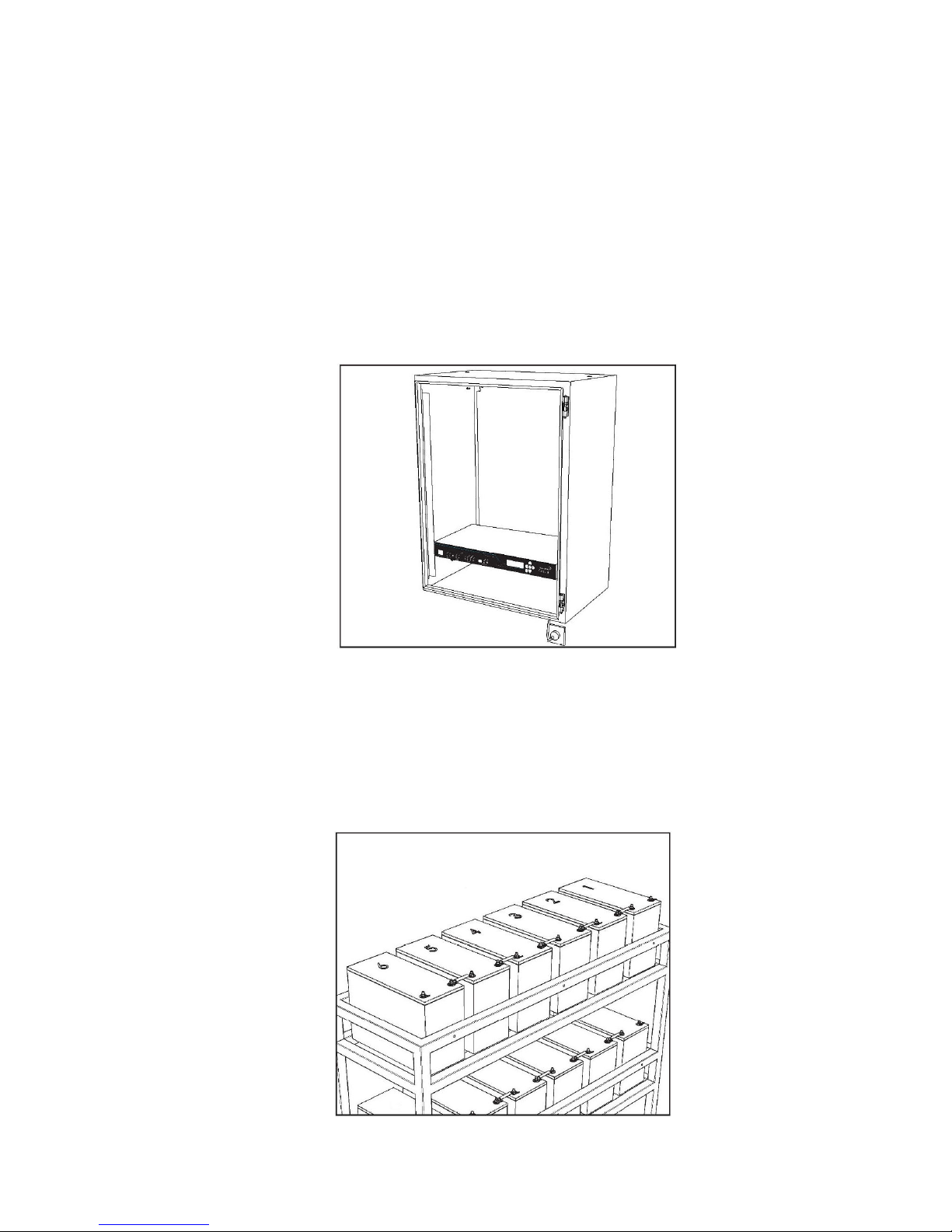
5.2 Number Blocks
Each block in string must be uniquely identified with a sequential number starting at 1, e.g. 1-32, 1-40 etc. For ease of
mapping of mSensors to blocks and subsequent system configuration, it is recommended to start numbering at the most
positive block in the string.
Page 15
___________________________________________________________________________________________________________
Part Number 6300-095D Page 15 of 43
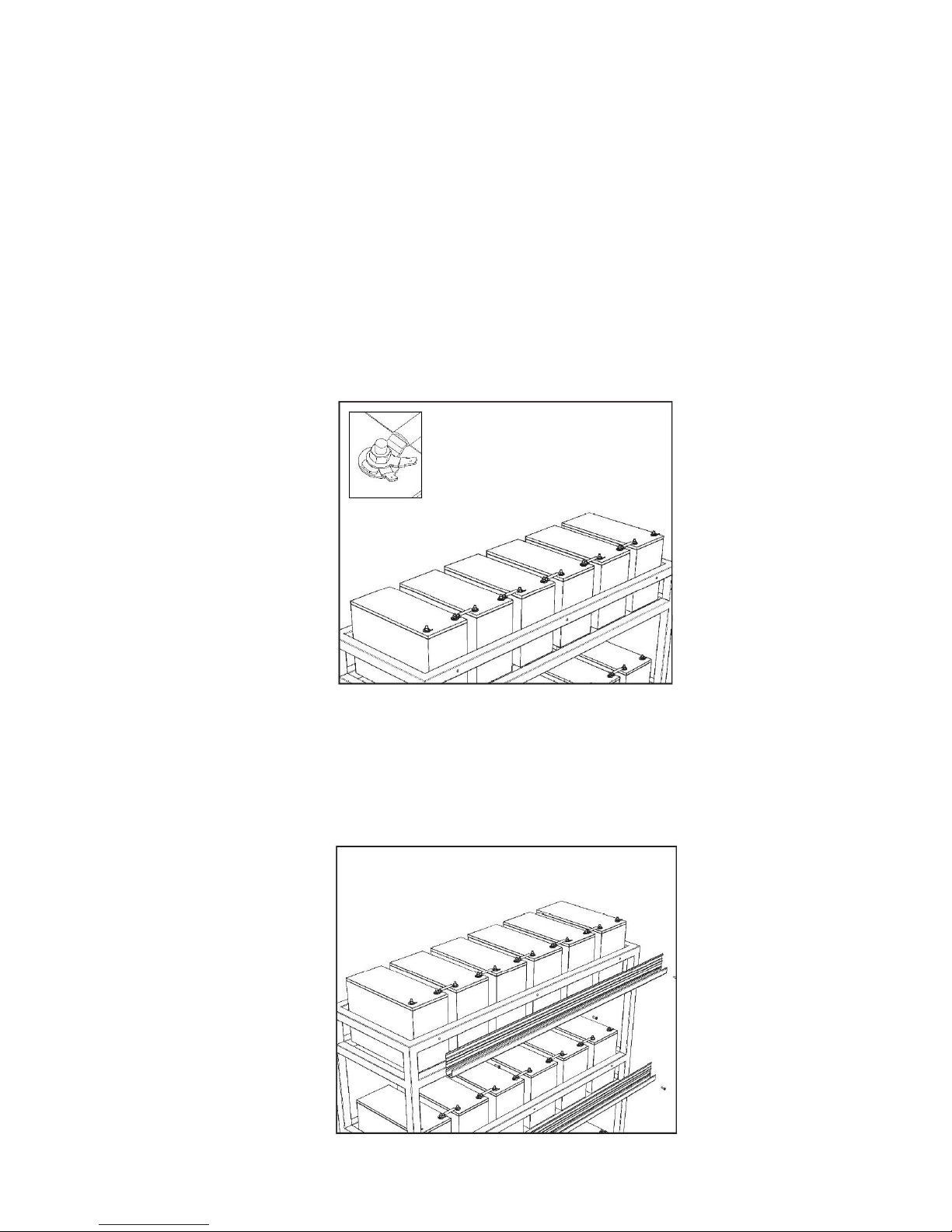
5.3 Block Terminal Tags
Ensure that all blocks have appropriate terminal tags fitted for connection to the mSensors as follows. For simplicity, it
may be easier and more efficient to fit two tags to every terminal.
• Where a dual mSensor is to be used with a pair of blocks, fit two tags on the negative (-) terminal of the
most negative block and two tags on the positive (+) terminal of the most positive block.
Fit one tag on each of the remaining terminals.
• Where a single mSensor is to be used on a single block, fit two tags on all block terminals.
NOTES: The terminal tags must be suitable for 6.3mm x 0.8mm receptacles. The tag material is important for
accurate measurements. PowerShield can supply a range of approved tags.
Place the tags on the top of the block interlinks and below any lock washers otherwise the current flow
between the interlink and the battery may be reduced and could result in a 'hot spot'.
Do not bend the tags as this can damage the connector crimp and/or result in poor or loose connections with
the mSensor power leads. Poor connections can have significant impact on impedance measurement.
PowerShield reserves the right to void warranties where terminal tags are bent or modified.
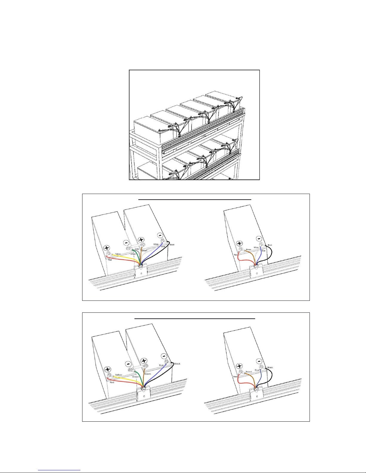
5.4 Mounting Rail for Hubs and mSensors
The mounting rail for the Hubs and mSensors can be fitted in any orientation and can be used with both battery racks
and cabinets. Drill to suit and fasten with screws or cable ties.
Page 16
___________________________________________________________________________________________________________
Part Number 6300-095D Page 16 of 43
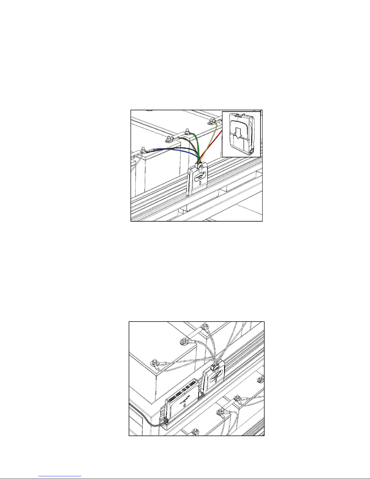
5.5 mSensor Power Leads
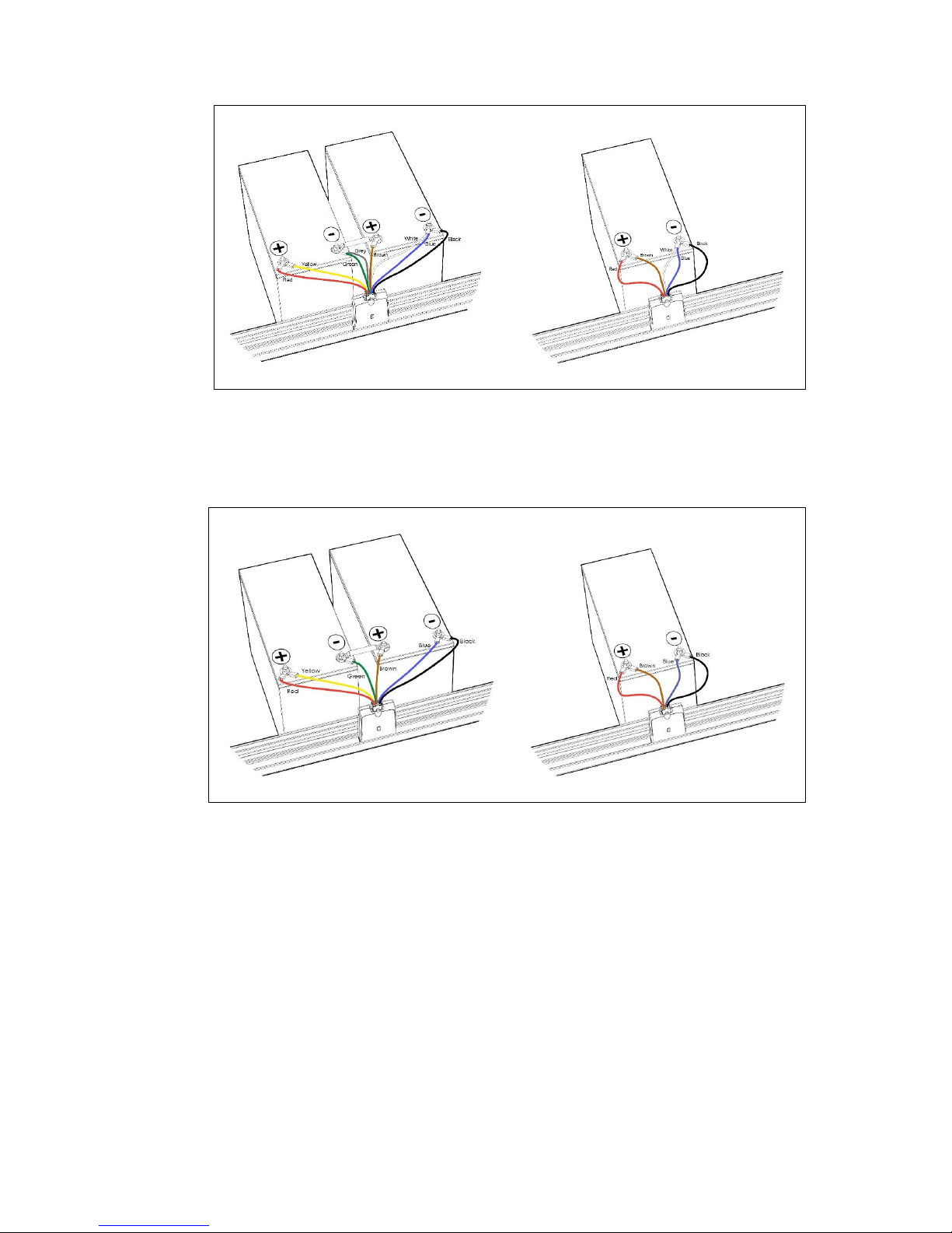
Fit the mSensor power leads to the block terminal tags with the correct polarity. Ensure the dual power leads are
connected across an ‘in series’ pair of batteries. Power leads are available with or without Block Temperature sensors.
Refer to Appendix 6 for the recommended method of connecting the mSensor power leads.
mSensor Power Leads with Block Temperature
Dual mSensor Single mSensor
mSensor Power Leads without Block Temperature
Dual mSensor Single mSensor
Page 17
___________________________________________________________________________________________________________
Part Number 6300-095D Page 17 of 43
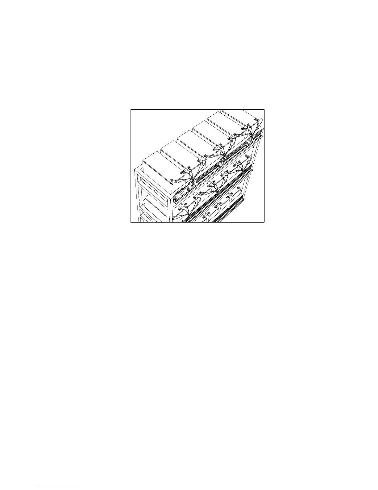
5.6 Connect mSensors to Blocks
Dual mSensors are numbered with IDs in the range 1 to 200 while single mSensors are numbered 201 to 220. For ease
of mapping of mSensors to blocks and subsequent system configuration, it is recommended to connect the mSensors to
the blocks in sequential order of ID. If single mSensors are being used for a string, install these as required but follow
the sequential ID order approach.
Plug the mSensors onto the power leads of the blocks. The mSensor LED should light solid green when the mSensor is
connected correctly. If the LED lights red, check the connections of the power lead at each block. A full list of mSensor
LED states is available in Appendix 2.
Insert the mSensor into the mounting rail when done.
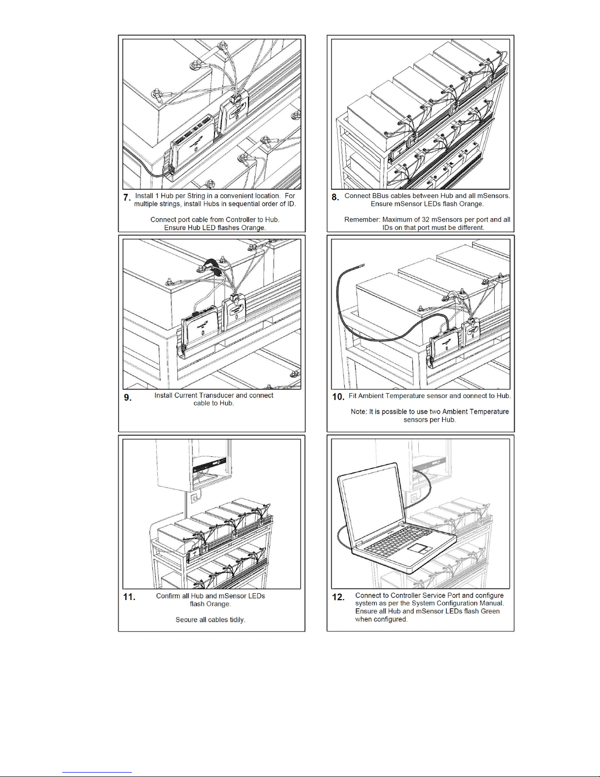
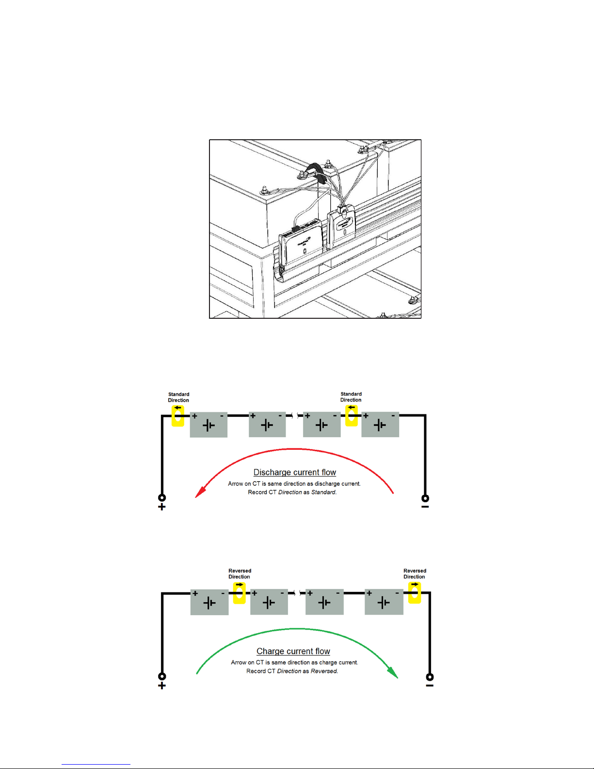
5.7 Install Hub
A PowerShield Hub is required per string to measure string current and ambient temperature. Hubs are numbered with
IDs in the range 221 to 230. Use Hub ID 221 for the first string and subsequent sequentially numbered Hubs for
multiple string systems (where applicable).
Insert the Hubs into the same mounting rail as the mSensors and connect CAT5 cable from the PowerShield Controller
hub ports to each Hub. The Hub LED should flash orange if all is correct. A full list of Hub LED states is available in
Appendix 2.
Page 18
___________________________________________________________________________________________________________
Part Number 6300-095D Page 18 of 43
5.8 Connect BBus Cables
Connect the mSensors and Hub using suitable lengths of BBus interconnecting cables in a daisy chain fashion. Note
that each PowerShield Controller hub port must not have more than 33 devices connected to it (1 Hub and up to 32
mSensors). In addition, the IDs of all devices on a single hub port must be different. The same IDs can be used on
other hub ports.
For strings with a high number of blocks and mSensors, mSensors can be connected directly to additional PowerShield
Controller hub ports using a CAT5-to-BBus adaptor which is available from PowerShield.
The mSensor LEDs should flash orange if all is correct. A full list of mSensor LED states is available in Appendix 2.
Page 19
___________________________________________________________________________________________________________
Part Number 6300-095D Page 19 of 43
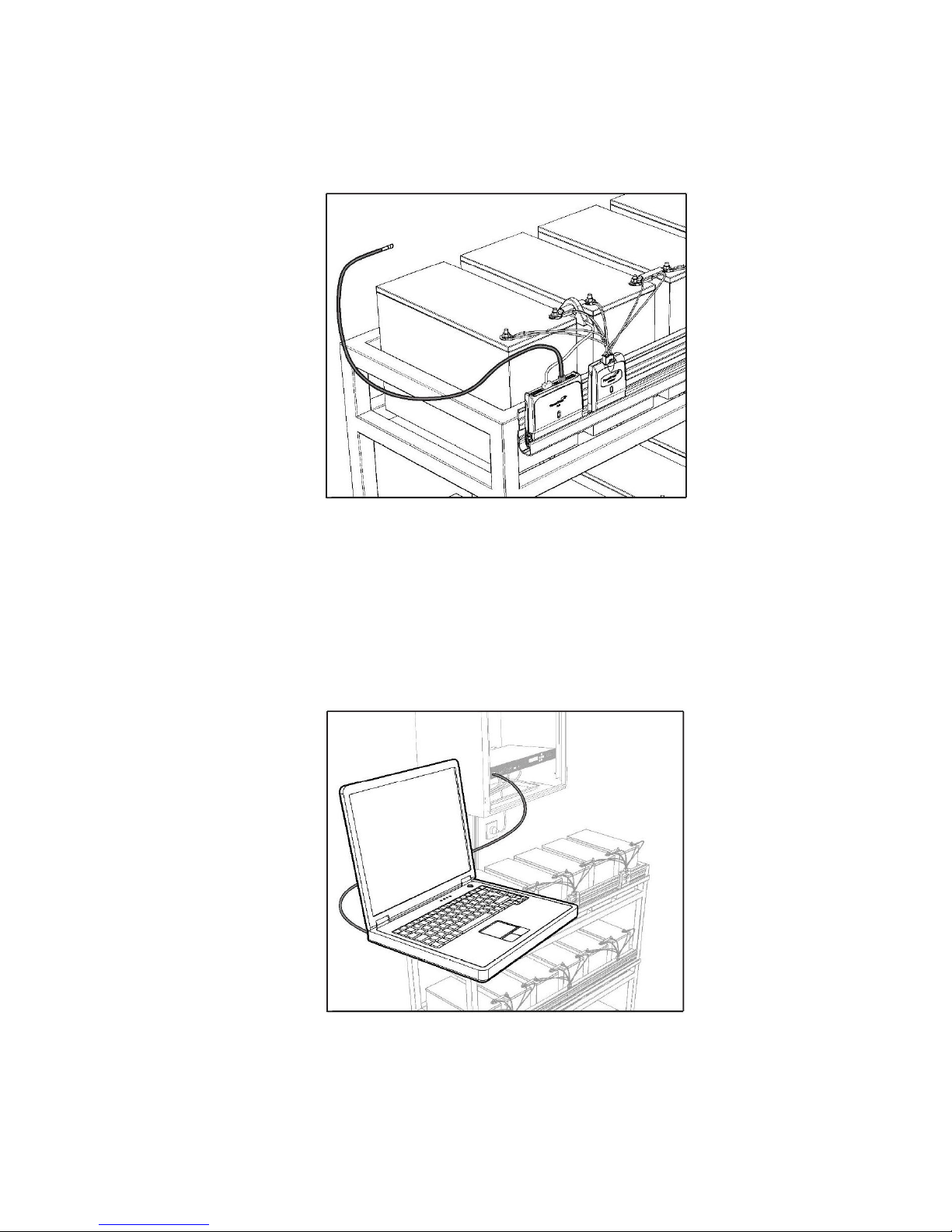
5.9 Install Current Transducer
A current transducer (CT) is required per string to measure string current. Install the current transducer anywhere on
the primary string conductor and plug the current transducer cable into the Current connector of the PowerShield Hub.
NOTE: Ensure the current transducer selected has the appropriate rating for the expected string charge and
discharge currents. The nominal rating of the current transducer should be similar to the typical maximum
expected current flow. The current transducer has a measurement range of ±150% of the nominal rating.
IMPORTANT: The direction of the current transducer is important. The transducer has an arrow on it to show the
direction of current flow.
• If the current transducer is installed with its arrow pointing in the direction that current flows during a
discharge event, the current transducer direction is considered to be Standard.
• If the current transducer is installed with its arrow pointing in the direction that current flows during a charge
event, the current transducer direction is considered to be Reversed.
Page 20
___________________________________________________________________________________________________________
Part Number 6300-095D Page 20 of 43
5.10 Connect Ambient Temperature Probe(s)
Up to two ambient temperature sensors can be used with each Hub to measure local ambient temperature(s).
Secure the ambient temperature sensor(s) in appropriate locations in or around the battery rack or cabinet but be aware
of other factors that may affect the local environment such as HVAC, fans or other devices.
5.11 Confirmation and Configuration
Check that all installed parts are performing as expected and secure all cables with appropriate strain relief.
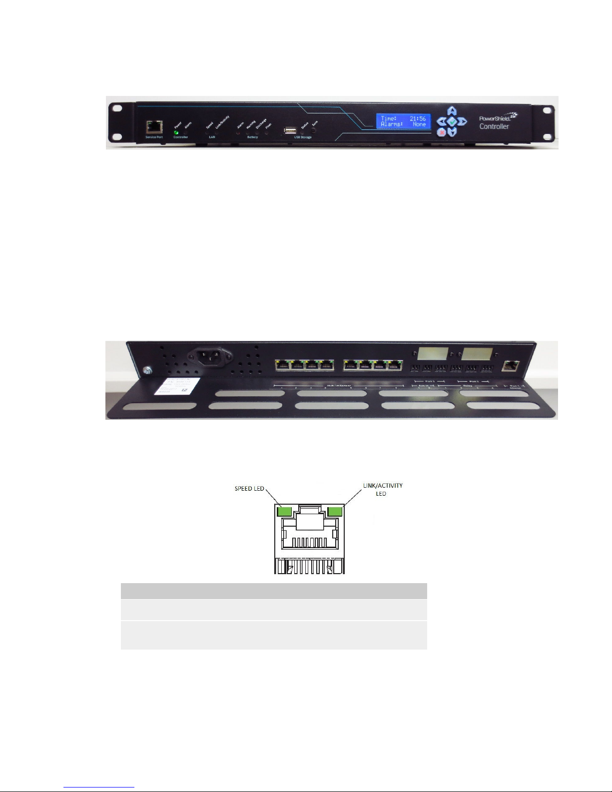
Complete the forms as in Appendix 12, connect to the Service Port Ethernet connector on the front of the PowerShield
Controller and configure the system.
Refer to the PowerShield Controller User Manual (part number 6300-103) for more details on configuring the system.
NOTE: All Hub and mSensor LEDs should flash green if the system is installed and configured correctly.
Page 21
___________________________________________________________________________________________________________
Part Number 6300-095D Page 21 of 43
Appendix 1 – Controller Panels
Front Panel
The front panel has the following features:
• Service Port: This is an Ethernet port that can be used to temporarily connect to the PowerShield Controller
on site.
• LEDs: These indicate system behaviour. Refer to Appendix 2 for a description of the LED states.
• USB Port: The USB Port can be used to copy Controller data and configuration files to a USB Flash Drive.
• USB Save Button: This button is used to start the copying of files to the USB Flash Drive.
• LCD: The LCD displays some system information. Navigation is via the 6-key keypad. Refer to Appendix 3
for a description of the LCD menu system and information displayed.
Rear Panel
The rear panel has the following features (viewed from right to left):
• Port 1: This is an Ethernet port that is intended as a permanent LAN connection for the PowerShield
Controller. The behaviour of the LEDs are as follows:
Name
Colour
Description
Speed Green On if LAN connection is operating at 1Gbps.
Link/Activity Green On if LAN Ethernet link is up.
Flashes during activity.
• Port 2 & 3: These ports are for optional communication devices. Refer to Appendix 4 for more details.
• Relays: The PowerShield Controller has 4 relays that can be used to control or trigger external devices when
certain events occur. Refer to Appendix 5 for details of the relay terminals.
• Auxiliary Inputs: The PowerShield Controller has 2 dry contact inputs that can be used to read the state of
external devices. Refer to Appendix 5 for details of the Auxiliary Inputs.
Page 22
___________________________________________________________________________________________________________
Part Number 6300-095D Page 22 of 43
• Hub Ports: The PowerShield Controller has 8 hub ports that can be used to communicate with Hubs or
mSensors. The behaviour of the LEDs on each hub port are as follows:
Name
Colour
Description
Transmit Yellow
Flashes when the Controller is transmitting data.
Receive Green
Flashes when the Controller is receiving data.
• Power Connector: The PowerShield Controller is available in AC input or DC input models.
The
AC input model has a standard 3-pin male IEC 60320 C14 appliance inlet as shown below:
1 2 3
Pin Function
1 (Left) Neutral
2 (Centre) Earth
3 (Right) Live
The D
C input models are fitted with a male 3 way input socket as shown below:
1 2 3
Pin Function
1 (Left) DC supply positive
2 (Centre) Earth
3 (Right) DC supply negative
The DC input models are supplied with a mating female screw terminal plug. Refer to Appendix 8 for wiring
details of the DC input model plug.
• Cable Tray: The case features a cable tray that extends beyond the rear panel connectors. Cables can be
secured to the cable tray to prevent them being accidentally unplugged and provide some strain relief.
Page 23

___________________________________________________________________________________________________________
Part Number 6300-095D Page 23 of 43
Appendix 2 – LED Behaviour
PowerShield Controller LEDs
The PowerShield Controller has LEDs on the front panel for on-site information. They will exhibit varying behaviour as
described below:
Name Colour Description
Controller Power Green On continuously when powered.
Controller Alarm Red On continuously if the PowerShield Controller has an
internal system fault.
Should be off under normal circumstances.
LAN Speed Green On if LAN connection is operating at 1Gbps.
LAN Link/Activity Green On if LAN Ethernet link is up.
Flashes during activity.
Battery Alarm Red On if there is a battery or string alarm.
Battery Warning Orange On if there is a battery or string warning.
Battery Discharge Orange On if all strings are in discharge.
Flashes if one or more strings in discharge.
Battery Float Orange On if all strings are in float.
Flashes if one or more strings in float.
USB Status Orange Off if there is no external USB device present or when
it is safe to unplug the device.
On if the USB device is ready for use.
This state should occur shortly after a device has been
plugged in and detected successfully.
Flashes during activity.
Note:
Pressing the USB Save button also affects the state of
the USB Status LED.
Page 24

___________________________________________________________________________________________________________
Part Number 6300-095D Page 24 of 43
mSensor and Hub LEDs
The mSensor and Hub have tri-colour LEDs that will exhibit varying behaviour as described below. The behaviour is the
same for both devices.
Colour State Description
Green Continuous Device is connected correctly.
For an mSensor, this indicates that the sensor is connected correctly to the
batteries being monitored and the battery voltages are appropriate.
Red Continuous Device is not connected correctly of has a fault.
For an mSensor, this may indicate that the sensor has detected a problem
with the wiring harness or battery.
Orange Continuous Device is in locate mode.
Green Single Flash Device is detected and operating as normal.
No warnings or alarms detected.
Orange Double Flash Device is receiving communication but has not been detected by the
PowerShield Controller.
White Continuous
Applies to Hub only.
Device is in boot loader mode and waiting for commands.
White Single Flash
Applies to Hub only.
Device is in boot loader mode and updating firmware.
Notes:
Single Flash = On for 0.25s, off for 3.75s.
Double Flash = On for 0.25s, off for 0.25s, on again for 0.25s and then off for 3.25s
.
Page 25
___________________________________________________________________________________________________________
Part Number 6300-095D Page 25 of 43
Appendix 3 – Controller LCD
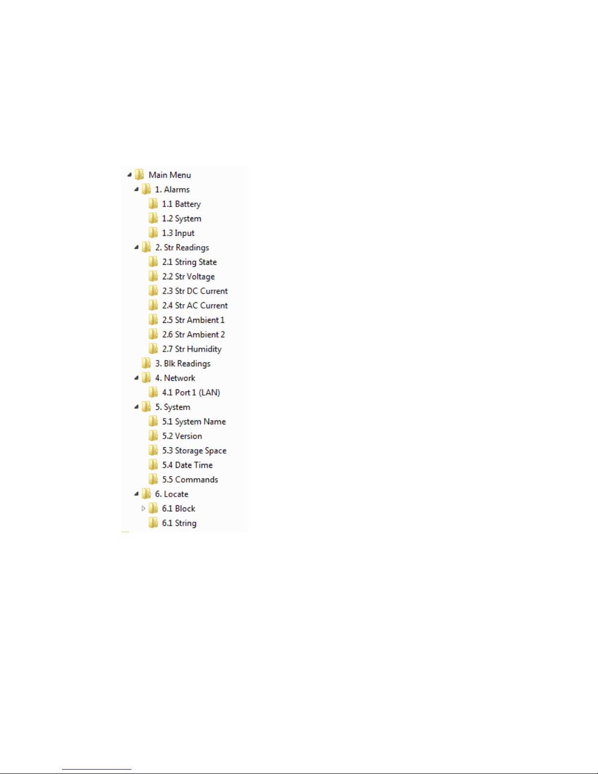
The PowerShield Controller LCD can be used to view system information. The information is displayed by pressing the
keypad buttons to access the required levels as shown below. The buttons operate as follows:
• Use the
buttons to scroll through the menu levels.
• Use the
button to select a level.
• Use the button to return to the previous level.
• The menu system is shown below:
Page 26
___________________________________________________________________________________________________________
Part Number 6300-095D Page 26 of 43
Appendix 4 – Communication Options
The PowerShield Controller has two internal slots for optional communication cards. The connectors for these cards will
be fitted to the Port 2 or Port 3 openings in the rear panel.
These cards offer an optional way of communicating with the PowerShield Controller using a MODBUS RTU protocol.
Refer to the PowerShield Controller User Manual (part number 6300-103) for details of how to configure the cards.
RS-485
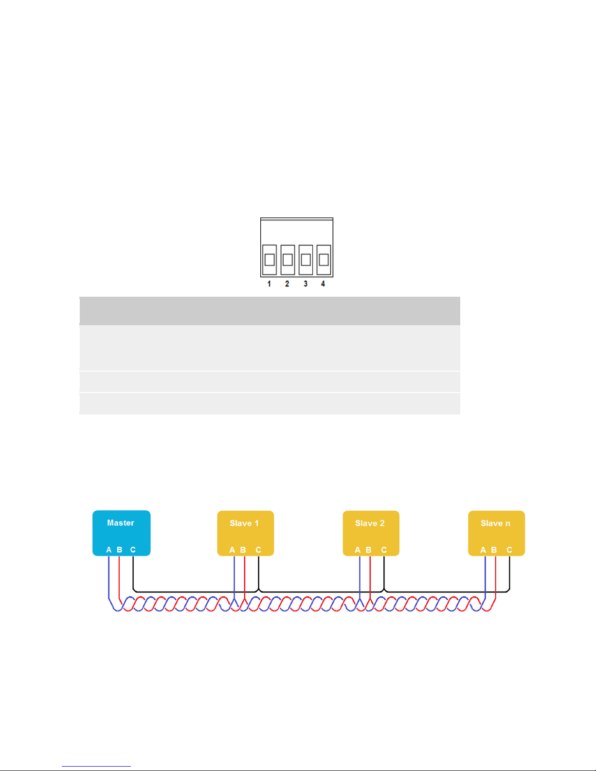
The RS-485 card implements 2-wire (half-duplex) transmission. The RS-485 signals can be accessed at the 4-way
screw terminal connector on the rear panel of the PowerShield Controller as shown below. If more than one Slave is on
the RS-485 bus, connect the additional Slaves using a daisy-chain approach and join the signal wires at the 4-way
connector.
Pin Name Function
1, 4 Common (C) Common signal reference ground for RS-485 differential pair.
This should be connected to the ground of the Master device for correct
signal level translation and to limit common mode voltages.
2 Data+ (B) Positive signal of RS-485 differential data pair.
3 Data- (A) Negative signal of RS-485 differential data pair.
Cabling & Termination
The diagram below illustrates a RS-485 Master with multiple Slaves.
It is recommended to use twisted pair wire for the RS-485 signals for improved noise immunity.
For long cable runs or where signal reflections are an issue, it is good practice to terminate the signal wires at each end
of the cable with a resistor equal to the characteristic impedance of the cable. A typical value for 24 AWG twisted pair
cable is 120Ω.
To terminate the cable at the PowerShield Controller, fit a suitable resistor between pins 2 & 3 of the 4-way connector.
Page 27
___________________________________________________________________________________________________________
Part Number 6300-095D Page 27 of 43
Appendix 5 – Relays and Auxiliary Inputs
Relays
The PowerShield Controller has four relays that can be used to trigger a piece of external equipment when certain events
are detected. For example, a relay could be used to turn on a light, sound a beeper or trigger an input to a
SCADA/Building Management System when the event occurs. The relay will be in its normal state when the event it is
associated with is not active. If the event occurs, the relay will be activated.
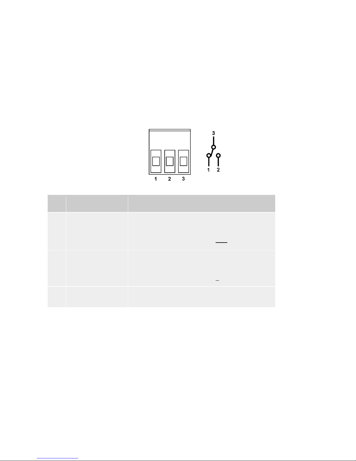
The relays are Single Pole Double Throw relays and have 3 terminals as shown below (illustration shows relay in not
activated state). The relay terminals can be accessed at the rear panel of the PowerShield Controller using screw
terminal connectors.
The relay contacts are rated for 1A, 30VDC. They must not be used to switch higher, AC or DC, voltages.
Pin Name Function
1 Normally closed contact The Common Contact is connected to this pin when the relay is
not activated.
Connect external circuit to this pin and the Common Contact if you
want the circuit to be on when the relay is not activated.
2 Normally open contact The Common Contact is connected to this pin when the relay is
activated.
Connect external circuit to this pin and the Common Contact if you
want the circuit to be on when the relay is activated.
3 Common contact Connects to Normally Open or Normally Closed contact
depending on relay state.
Auxiliary Inputs
The PowerShield Controller has two auxiliary inputs that can be used to read the state of a dry contact switch in third
party equipment. To activate the auxiliary input simply short the terminals of the non-polarised two way connector.
Page 28
___________________________________________________________________________________________________________
Part Number 6300-095D Page 28 of 43
Appendix 6 – mSensor Power Lead Connection
It is important to connect and install the mSensor power lead correctly. The following diagrams show the recommended
method of connecting an mSensor to blocks with 2 or 4 terminals per block.
Failure to connect and install the mSensor power lead correctly may lead to unacceptable variation in readings between
sensors.
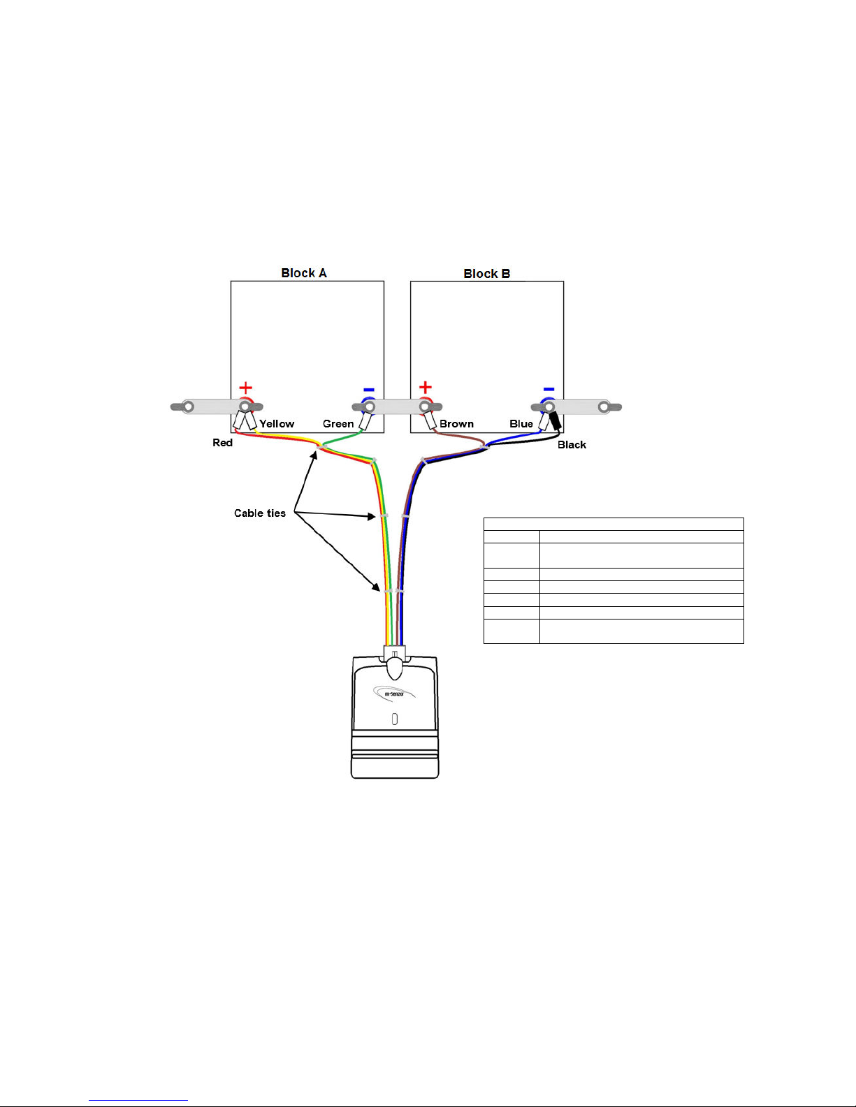
Dual mSensor and Blocks with 2 Terminals
Dual mSensor
Power Lead
Wires
Wire Function / Block Connection
Red Positive Power wire for sensor.
Connect to positive terminal of Block A.
Yellow Positive Sense wire for Block A.
Green Negative Sense wire for Block A.
Brown Positive Sense wire for Block B.
Blue Negative Sense wire for Block B.
Black Power return wire for sensor.
Connect to negative terminal of Block B.
Please note the following important points:
• The power lead is manufactured with cable ties in order to keep the Sense wire pairs and the Power wires
closely coupled.
• Try to keep the Sense wire pairs and Power wires closely coupled as much as possible.
• Where possible, do not remove the cable ties.
• The cable ties nearest the block terminals may be need to be repositioned to allow the wires to be
connected to the block terminals.
• Do not connect the Green and Brown Sense wires to the terminal of one block. Connect them to the
positive and negative terminals of the respective blocks.
Page 29
___________________________________________________________________________________________________________
Part Number 6300-095D Page 29 of 43
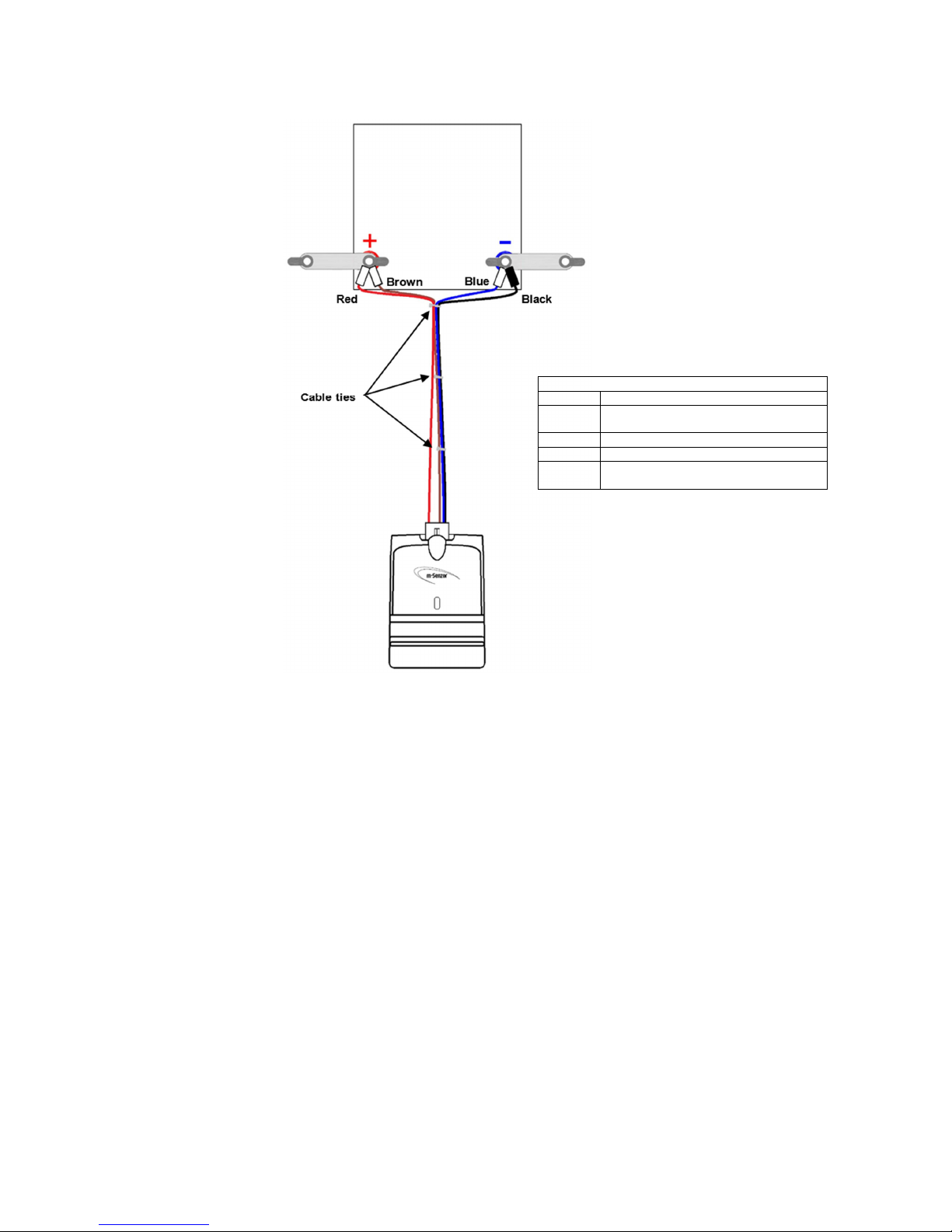
Single mSensor and Block with 2 Terminals
Single
mSensor
Power Lead
Wires
Wire Function / Block Connection
Red Positive Power wire for sensor.
Connect to positive terminal of Block.
Brown Positive Sense wire for Block.
Blue Negative Sense wire for Block.
Black Power return wire for sensor.
Connect to negative terminal of Block.
Please note the following important points:
• The power lead is manufactured with cable ties in order to keep the Sense wire pairs and the Power wires
closely coupled.
• Try to keep the Sense wire pairs and Power wires closely coupled as much as possible.
• Where possible, do not remove the cable ties.
• The cable ties nearest the block terminals may be need to be repositioned to allow the wires to be
connected to the block terminals.
Page 30
___________________________________________________________________________________________________________
Part Number 6300-095D Page 30 of 43
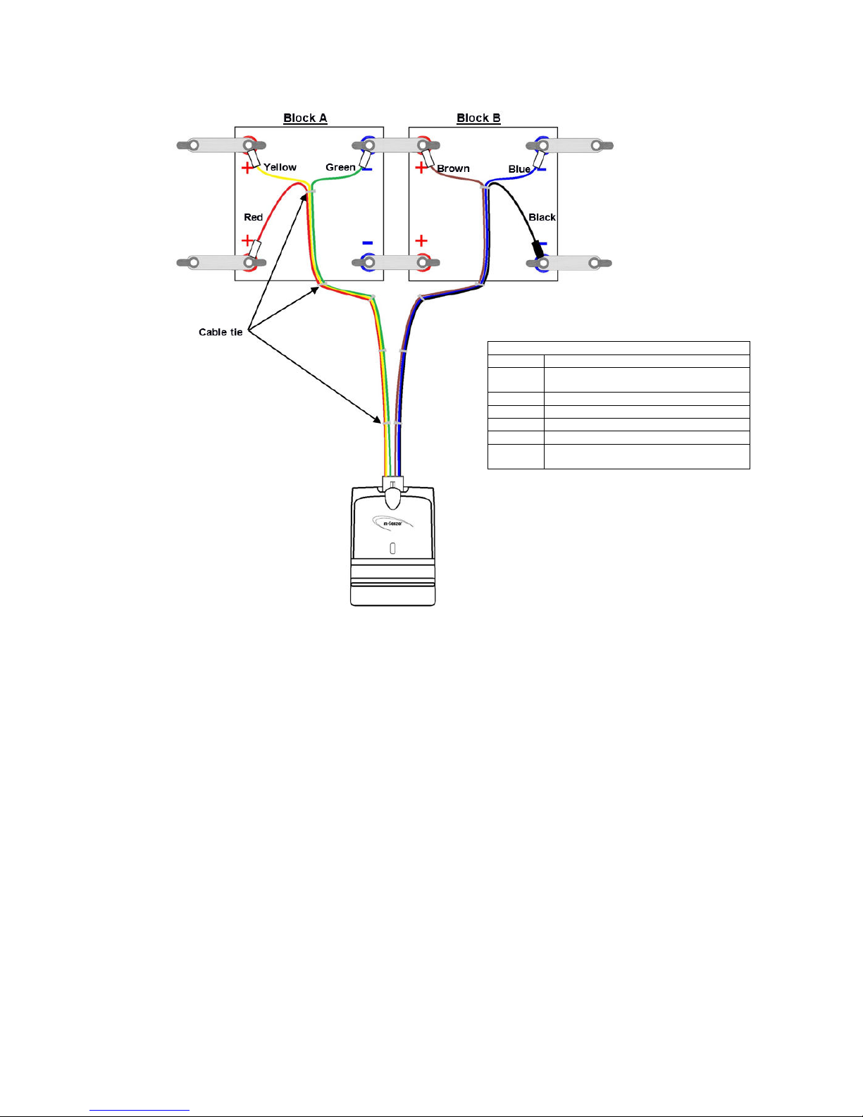
Dual mSensor and Blocks with 4 Terminals
Dual mSensor
Power Lead
Wires
Wire Function / Block Connection
Red Positive Power wire for sensor.
Connect to positive terminal of Block A.
Yellow Positive Sense wire for Block A.
Green Negative Sense wire for Block A.
Brown Positive Sense wire for Block B.
Blue Negative Sense wire for Block B.
Black Power return wire for sensor.
Connect to negative terminal of Block B.
Please note the following important points:
• The power lead is manufactured with cable ties in order to keep the Sense wire pairs and the Power wires
closely coupled.
• Try to keep the Sense wire pairs and Power wires closely coupled as much as possible.
• Where possible, do not remove the cable ties.
• The cable ties nearest the block terminals may be need to be repositioned to allow the wires to be
connected to the block terminals.
• Do not connect the Red and Black Power wires to the same terminals as the Yellow and Blue Sense wires.
• Do not connect the Green and Brown Sense wires to the terminal of one block. Connect them to the
positive and negative terminals of the respective blocks.
Page 31
___________________________________________________________________________________________________________
Part Number 6300-095D Page 31 of 43
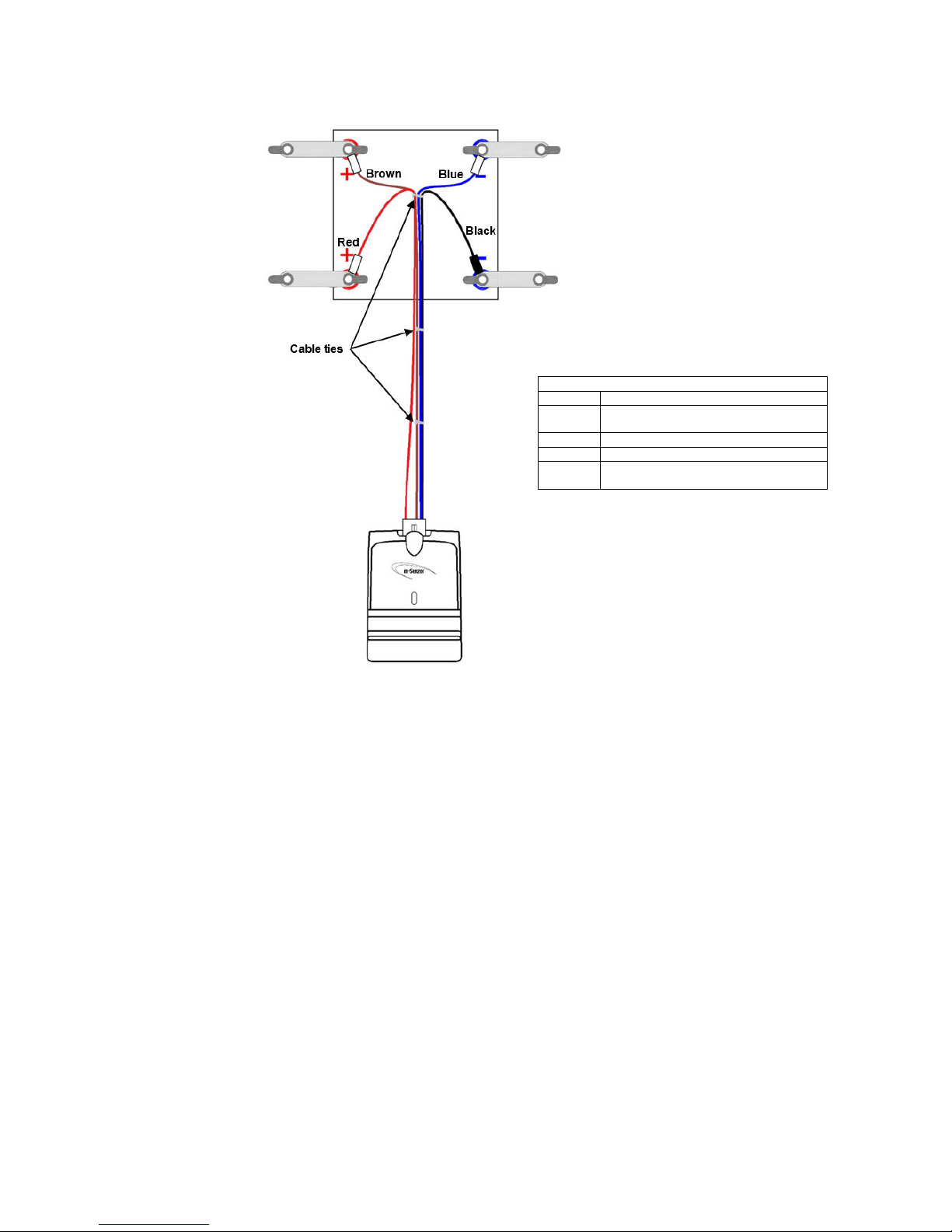
Single mSensor and Block with 4 Terminals
Single
mSensor
Power Lead
Wires
Wire Function / Block Connection
Red Positive Power wire for sensor.
Connect to positive terminal of Block.
Brown Positive Sense wire for Block.
Blue Negative Sense wire for Block.
Black Power return wire for sensor.
Connect to negative terminal of Block.
Please note the following important points:
• The power lead is manufactured with cable ties in order to keep the Sense wire pairs and the Power wires
closely coupled.
• Try to keep the Sense wire pairs and Power wires closely coupled as much as possible.
• Where possible, do not remove the cable ties.
• The cable ties nearest the block terminals may be need to be repositioned to allow the wires to be
connected to the block terminals.
• Do not connect the Red and Black Power wires to the same terminals as the Brown and Blue Sense wires.
Page 32
___________________________________________________________________________________________________________
Part Number 6300-095D Page 32 of 43
mSensor Power Leads with Block Temperature
Dual mSensor Single mSensor
mSensor Power Leads without Block Temperature
Dual mSensor Single mSensor
Page 33
___________________________________________________________________________________________________________
Part Number 6300-095D Page 33 of 43
Appendix 7 – 4-Wire / Kelvin Connection
This article explains the 4-wire or Kelvin connection measurement technique in general terms. It is not intended as an indepth guide to making high accuracy measurements of battery impedance.
Resistance
Resistance is commonly measured by passing a known test current through the resistance under test and measuring the
corresponding voltage. The value of resistance is then determined from Ohms law:
R = V/I
where:
R = resistance
V= measured voltage
I = known test current
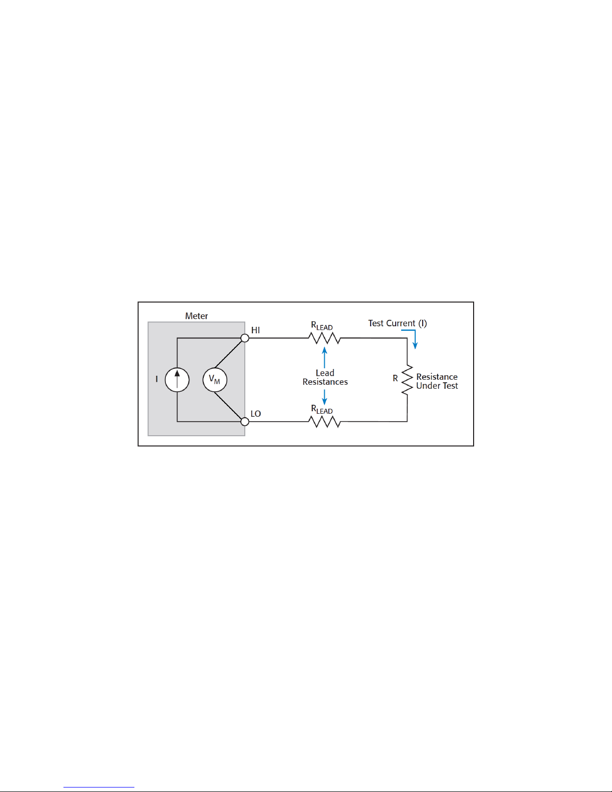
2-Wire Resistance Measurement
Simple meters measure resistance using 2 leads or probes. Internally, the meter generates a test current that is driven
through the resistance under test while simultaneously measuring the voltage at the terminals of the meter. The diagram
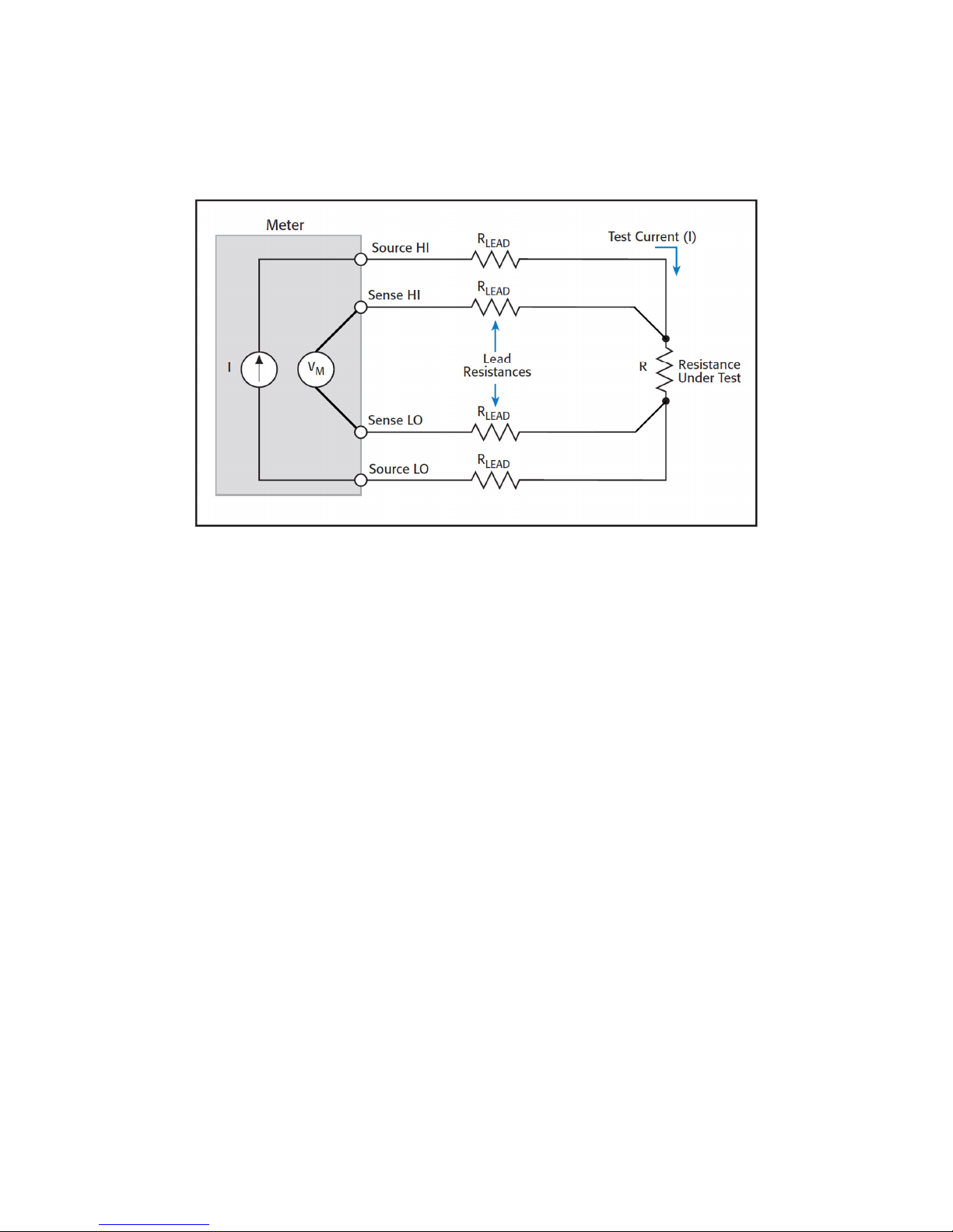
below illustrates this principle.
Note that the meter leads have resistance (denoted R
Lead
above). The points of contact of the meter probes with the
resistance under test also have resistance (denoted R
Contact
, not shown above).
As the meter measures the voltage at its terminals, the voltage developed is due to the total of all resistances in the
external circuit, i.e. R, R
Lead
& R
Contact
. If the lead and contact resistances are significant in value compared to the
resistance under test, the lead and contact resistances result in the meter reporting a higher value for the resistance
under test than its true value.
Example:
Typical meter probes can have resistances in the range 10mΩ to 50mΩ (a 1m length of 20AWG copper wire
has a resistance of approx. 33mΩ). Contact resistance is usually comparable. If the total lead and contact
resistance is 20mΩ and the true value of the resistance under test is also 20mΩ, the meter will report the
resistance to be 40mΩ. Thus, the resistance measurement error is 20mΩ or 100% (20mΩ / 20mΩ).
NOTES:
• Some meters try to compensate for the lead and contact resistances using a Null or Calibration function.
These functions require making a resistance measurement with either the tips of the probes shorted together
or placed across a known, calibrated resistance or shunt. The measured value is then subtracted from
subsequent measurements.
• Meters using the 2-wire method are generally only capable of measuring resistance to just under 1Ω with
accuracy of about 50 to 100mΩ as they do not have adequate accuracy or resolution.
Page 34
___________________________________________________________________________________________________________
Part Number 6300-095D Page 34 of 43
4-Wire/Kelvin Resistance Measurement
To reduce the effect of lead and contact resistances, the 4-wire or Kelvin connection method can be used. This method
requires 4 wires and thus 4 terminals at the meter as shown below. With this configuration, the test current is driven
through the resistance under test using one set of leads called the Source leads. The voltage developed across the
resistance under test is measured by another set of leads called the Sense leads. The Sense leads should be
connected as close as possible to the resistance under test for highest accuracy.
With this method, the test current does not flow in the Sense leads so there is no voltage developed across their
resistance. In addition, as the Sense leads are connected directly at the resistance under test, the voltage developed by
the test current flowing through the resistance of the Source leads is not measured. Thus, the meter only measures the
voltage due the test current flowing through the resistance under test which results in a more accurate reading that is not
influenced by the meter leads.
NOTES:
• A very small, negligible, current does flow in the Sense leads due to the input circuitry of the meter. As long
as this current is much smaller than the test current, it does not significantly affect the resistance
measurement and can be ignored.
• The method of physically connecting the leads at the resistance under test can affect the measurement. If
there is any appreciable contact resistance at the resistance under test due to the physical position of the
leads, this contact resistance can be measured by the meter and offset the true resistance measurement.
The internal resistance of batteries used with large UPS can range from less than 1mΩ for 2V batteries up to
20mΩ for 12V batteries so we can see that a 2-wire approach can result in a large measurement error if lead and
contact resistance are not considered.
The 4-wire or Kelvin connection method is recognised as the most accurate way to measure resistance when high
accuracy and/or low sample resistances are involved.
Page 35
___________________________________________________________________________________________________________
Part Number 6300-095D Page 35 of 43
Appendix 8 – DC Model Controller Wiring
The D
C model PowerShield Controllers are fitted with a male 3 way input socket and are supplied with a mating female
screw terminal plug. The following points must be considered:
• The Controller must be installed by a service person and connected to a socket outlet or fixed wiring with a
protective earth conductor or connector.
• A readily available disconnect device shall be incorporated in the building wiring or the socket outlet near
the PowerShield Controller that is readily accessible.
• The power source for the PowerShield Controller must be fused with a circuit breaker of no greater than 20A
rating. The connection must be installed in a service access area.
DC Model Plug
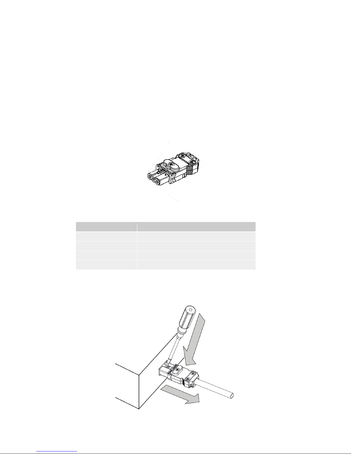
The plug required to connect to a DC model PowerShield Controller is a Wieland GST15i3 3-pole female screw terminal
plug (Wieland part number 91.931.3053.1) as shown below. This plug is supplied with the PowerShield Controller.
The plug specifications are shown below. It must be wired with cable of appropriate gauge and rating. We recommend
using cable with minimum ratings of 5A 250V.
Parameter Specification
Rated Voltage 250V
Rated Current 16A
Cable outer diameter 5.5mm to 9.0mm
Wire cross sectional area 0.5mm2 to 1.5mm2
The plug is fitted with a latch to secure it to the input socket of the PowerShield Controller. To remove the plug, press
down on the latch with a screwdriver or suitable tool and pull the plug out.
Page 36
___________________________________________________________________________________________________________
Part Number 6300-095D Page 36 of 43
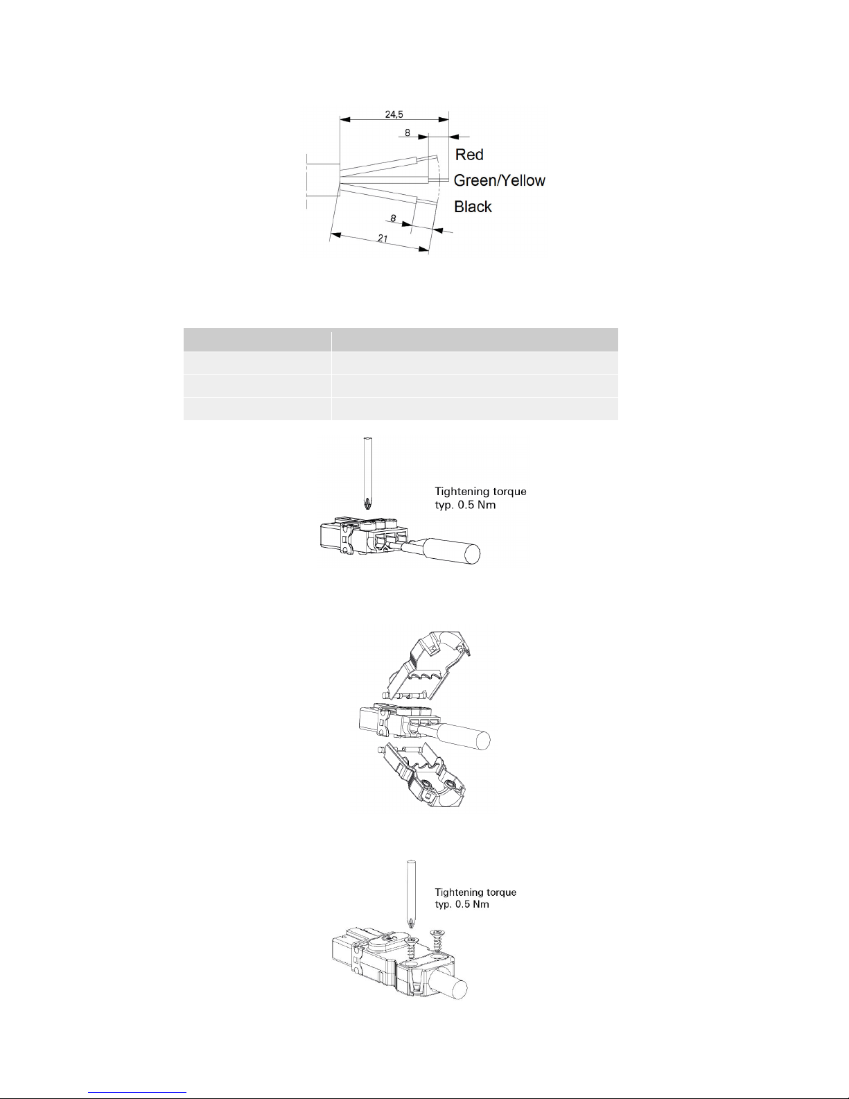
To wire and assemble the plug, please complete the following steps:
1. Remove the outer cable sheath and strip the ends of each wire as per below (lengths are in mm):
2. Insert the wires into the plug and tighten the contact screws.
The wiring should be as follows:
Plug Terminal Wire / Function
Live Red / DC supply positive
Earth Earth
Neutral Black / DC supply negative
3. Fit the covers.
4. Tighten the strain relief screws.
Page 37

___________________________________________________________________________________________________________
Part Number 6300-095D Page 37 of 43
Appendix 9 – Controller Specifications
Configuration Interface
Web browser
Communication
Front
Rear
1000Base-T Ethernet (Service Port)
USB (Flash drive only)
LCD
1000Base-T Ethernet (PowerShield Link software, Modbus TCP, SNMP)
RS485 (optional)
Hub Ports
Capacity
Connection
Maximum Distance
8
1 PowerShield Hub and up to 32 PowerShield mSensors
RJ45 / CAT5 cable
50m / 165ft (between Controller and Hub)
Memory
2GB RAM
4GB Flash
Relays
Type
Rating
4
Single Pole Double Throw (SPDT)
1A @ 30VDC, resistive
Auxiliary Inputs
Type
2
Voltage Free / Dry Contact
Physical Dimensions
1U High 19” rack mount enclosure, mild steel with powder coat finish
Width: 430mm / 16.9 inches
Depth: 265mm / 10.4 inches
Height: 45mm / 1.8 inches
Weight: 3kg / 6.6lbs
The Controller must be installed in a location that allows 30mm space at
the top and sides of the unit for adequate air circulation.
Installation must allow unrestricted airflow.
Power Supply
Power Consumption
AC Model: 90V to 260Vac, 50/60Hz, 0.42A max.
24V DC Model: 18V to 30Vdc, 1.1A max.
48V DC Model: 35V to 60Vdc, 0.52A max.
110V DC Model: 80V to 150Vdc, 0.22A max.
Typical 5W + 1.6W per Hub
Max. 6W + 1.8W per Hub
Environment
Indoor use only, Overvoltage Category II, Pollution Degree 2
Operating Temperature: 0°C to 50°C / 32F to 122F
Storage Temperature: 0°C to 70°C / 32F to 158F
Altitude: 2000m max.
Specifications subject to change.
Page 38

___________________________________________________________________________________________________________
Part Number 6300-095D Page 38 of 43
Appendix 10 – Hub Specifications
Block Inputs
Type
up to 64 (via dual PowerShield mSensors)
PowerShield mSensor
Current Inputs
Type
Range
Maximum Distance
1 (provides string DC & AC current)
Hall Effect
0A to ±2000A (depends on Current Transducer model used)
3m / 10ft
Temperature Inputs
Type
Range
Maximum Distance
2
Thermistor
-10°C to 80°C / 14F to 176F
15m / 50ft
Auxiliary Inputs
Type
2
Voltage Free / Dry Contact
Humidity
Type
Range
1
On-board sensor
0% to 100% Relative Humidity
Communication Interface
Connection
Type
Protocol
Maximum Distance
RJ45 / CAT5 cable
Proprietary differential bus
Modbus
25m / 82ft (total length of wiring from Hub to last mSensor)
Physical Dimensions
Width: 120mm / 4.7 inches
Depth: 107mm / 4.2 inches
Height: 25mm / 1.0 inch
Weight: 177g / 0.4lbs
Power Supply
24V DC via PowerShield Controller hub port
Environment
Indoor use only, Overvoltage Category II, Pollution Degree 2
Operating Temperature: -10°C to 50°C / 14F to 122F
Storage Temperature: -10°C to 80°C / 14F to 176F
Altitude: 2000m max.
Specifications subject to change
Page 39

___________________________________________________________________________________________________________
Part Number 6300-095D Page 39 of 43
Appendix 11 – mSensor Specifications
Block Inputs
Block Type
1 or 2 (depends if using a single or dual mSensor)
1.2V NiCad, 2V, 4V, 6V, 8V, 12V, 16V Lead Acid
Nominal Voltage
1
Voltage Range
Voltage Resolution
Voltage Accuracy
Ohmic Range2
Ohmic Resolution
Ohmic Accuracy
Maximum Input
NiCad
0.8 – 1.9V
1mV dc, 1mV ac
±0.3%
0.1 – 5mΩ
1uΩ
±2.5% + ±15uΩ
±5V
2V
1.6 – 2.6V
1mV dc, 1mV ac
±0.3%
0.1 – 5mΩ
1uΩ
±2.5% + ±15uΩ
±6V
6V
4.8 – 7.8V
5mV dc, 1mV ac
±0.2%
0.5 – 20mΩ
1uΩ
±2.5% + ±25uΩ
±25V
12V
9.6 – 15.6V
5mV dc, 1mV ac
±0.2%
1.0 – 40mΩ
1uΩ
±2.5% + ±25uΩ
±65V
Temperature Inputs
Type
Range
Accuracy3 / Resolution
Maximum Distance
1 per Block
Thermistor, located on Negative Terminal of Block
-10°C to 70°C / 14F to 158F
±1°C, 0.1°C
15m / 50ft
Communication Interface
Connection
Type
Protocol
Maximum Distance
Isolation
4P4C Modular Jack / 4-core flat modular cable
Proprietary differential bus
Modbus
25m / 82ft (total length of wiring from Hub to last mSensor)
UL certified to 600V DC (internal optical isolation)
Physical Dimensions
Width: 106mm / 4.2 inches
Depth: 75mm / 3.0 inches
Height: 25mm / 1.0 inch
Weight: 161g / 0.4lbs
Power Supply
Nominal Supply Current4
NiCad
50mA
2V
30mA
6V
18mA
12V
18mA
Environment
Indoor use only, Overvoltage Category 0, Pollution Degree 2
Operating Temperature: 0°C to 50°C / 32F to 122F
Storage Temperature: -10°C to 70°C / 14F to 158F
Altitude: 2000m max.
Specifications subject to change.
1. Most common models. Other models available on request.
2. NiCad single mSensor cannot perform ohmic measurement.
3. Over the range 0°C - 50°C.
4. From block(s) being monitored.
Page 40
___________________________________________________________________________________________________________
Part Number 6300-095D Page 40 of 43
Appendix 12 - PowerShield 8 Installation Forms
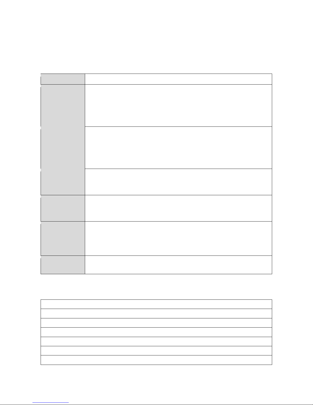
6300-107 Facility Information Form (FIF)
Facility Information
Company
/Customer
:
Facility Name:
Facility Address:
Total Number Strings:
Total Number
PowerShield 8
Systems
:
Installed by:
Date:
Notes
Page 41
___________________________________________________________________________________________________________
Part Number 6300-095D Page 41 of 43
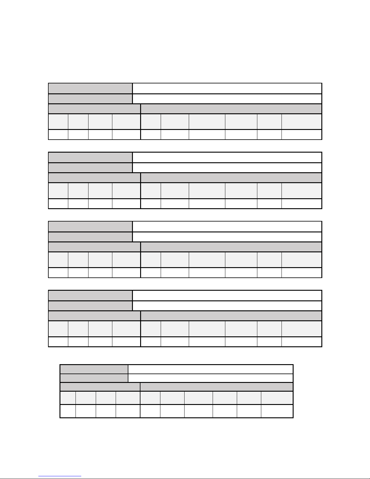
6300-108 PowerShield 8 Controller Information Form (CIF)
PRINT OUT AS MANY COPIES OF THIS FORM AS REQUIRED
Facility Name: ..........................................................
Controller Details
System Name:
Strings:
No. Monitored:
Details (No. Blocks/Voltage):
Port 1:
Connected (Yes / No):
Configuration (DHCP / Manual):
Manual Config.:
• Address:
• Subnet Mask:
• Gateway:
Port 2:
Installed (Yes / No):
Interface Type (RS485, RS232):
Baud Rate:
Port 3:
Installed (Yes / No):
Interface Type (RS485, RS232):
Baud Rate:
Relays:
#1 Function:
#2 Function:
#3 Function:
#4 Function:
Auxiliary Inputs:
#1 Function:
#2 Function:
Notes
Page 42
___________________________________________________________________________________________________________
Part Number 6300-095D Page 42 of 43
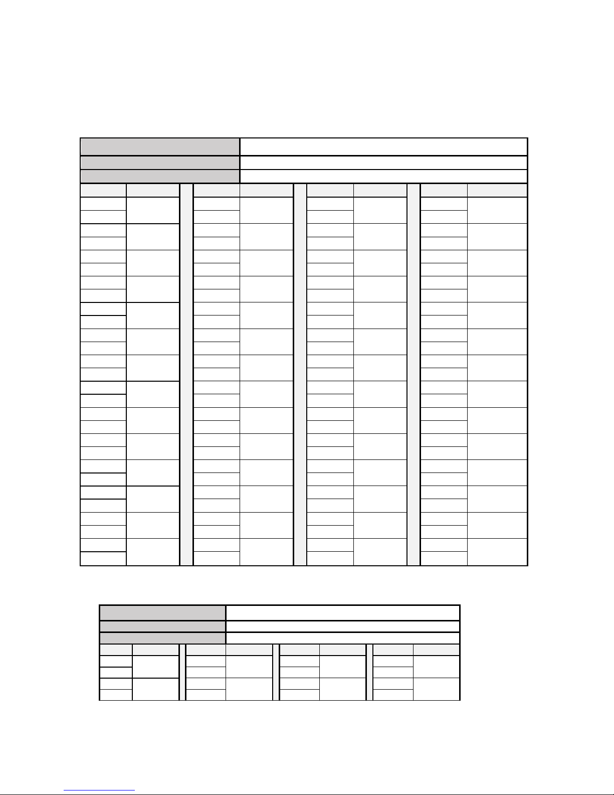
6300-109 PowerShield 8 String Information Form (SIF)
PRINT OUT AS MANY COPIES OF THIS FORM AS REQUIRED
Facility Name: ..........................................................
PowerShield 8 System Name: .................................
String # / Name:
No. mSensors (Singles / Duals):
Block Details
Hub Details
Block
Start #
Block
End #
Block
Voltage
Block Ah
Rating
Hub ID
Controller
Port #
CT Model
CT
Direction
Temp.
Sensors
Temp. Sensor
Location
String # / Name:
No. mSensors (Singles / Duals):
Block Details
Hub Details
Block
Start #
Block
End #
Block
Voltage
Block Ah
Rating
Hub ID
Controller
Port #
CT Model
CT
Direction
Temp.
Sensors
Temp. Sensor
Location
String # / Name:
No. mSensors (Singles / Duals):
Block Details
Hub Details
Block
Start #
Block
End #
Block
Voltage
Block Ah
Rating
Hub ID
Controller
Port #
CT Model
CT
Direction
Temp.
Sensors
Temp. Sensor
Location
String # /
Name:
No. mSensors (Singles / Duals):
Block Details
Hub Details
Block
Start #
Block
End #
Block
Voltage
Block Ah
Rating
Hub ID
Controller
Port #
CT Model
CT
Direction
Temp.
Sensors
Temp. Sensor
Location
Example
String # / Name:
1 / UPS A1
No. mSensors (Singles / Duals):
0 / 20
Block Details Hub Details
Block
Start #
Block
End #
Block
Voltage
Block Ah
Rating
Hub ID Controller
Port #
CT Model CT
Direction
Temp.
Sensors
Temp. Sensor
Location
1 40 12V 150Ah 221 1 L34S800D15 Standard 2 1 = Top
2 = Bottom
Page 43
___________________________________________________________________________________________________________
Part Number 6300-095D Page 43 of 43
6300-110 PowerShield 8 Block Mapping Form (BMF)
PRINT OUT AS MANY COPIES OF THIS FORM AS REQUIRED
Facility Name: ..........................................................
PowerShield 8 System Name: .................................
String # / Name:
Controller Port # / Hub ID:
Reverse Block Numbering (Yes/No):
Block
#
mSensor
ID
Block
#
mSensor
ID Block
#
mSensor
ID Block
#
mSensor
ID
Example
String # / Name:
1 / UPS A1
Controller Port # / Hub ID:
1 / 221
Reverse Block Numbering (Yes/No):
No
Block # mSensor ID
Block # mSensor ID Block # mSensor ID Block # mSensor ID
1 1 5 3 9 5 13 7
2 6 10 14
3 2 7 4 11 6 15 8
4 8 12 16
 Loading...