

Powerseal 3506, 3506LB, 3506AS, 3506EC Installation Manual
INSTALLATION SHEET - COUPLINGS
3506 - 3506LB - 3506AS - 3506EC - 3506R POWERMAX Coupling
GENERAL NOTES:
• Use cave-in protection during excavation and back-fill
operations.
• Verify Pipe O.D. to make certain that the correct Coupling
is being installed.
• Keep bolt threads clean and free from nicks, dents or other
damage.
• If conditions permit, mark the pipe for a reference point to
properly position the coupling.
• Clean and lubricate gaskets.
• Gaskets have a design allowance to fit a variety of
outside diameters and may appear loose on some
classes of pipe prior to tightening bolts
• Before start, the installer shall determine the suitability of
the product for his intended use and the installer assumes
all risk and liability for the application of the product.
OTHER INFO:
• FOR SS BOLTS: To avoid galling during installation, the
threads MUST BE KEPT CLEAN AND FREE FROM DAMAGE.
The fitting should not be thrown around or otherwise be
abused, i.e. stored on truck without box, dropped from top
of ditch, etc. A deep socket and ratchet wrench is
recommended.
• WARNING: this product does not restrain axial pipe
movement.
• To prevent coupling movement position pipe stop between
the pipes and firmly tighten.
• Note: Gaskets have a design allowance to fit a variety of outside
diameters and may appear loose on some classes of pipe prior to
tightening bolts.
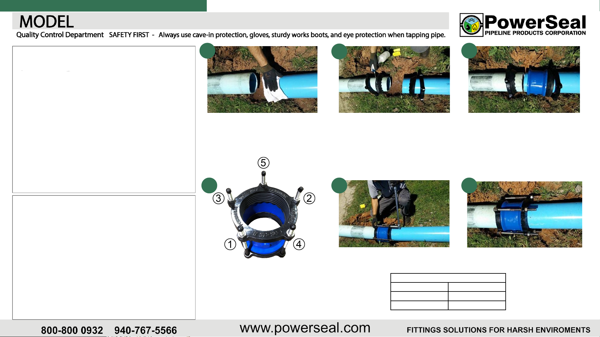
1
Thoroughly clean the pipe where the
coupling will be installed.
4
Install and evenly tighten bolts and nuts to
recommended torque alternating between
opposite sides of coupling.
* Deflection of up to 4º per side is allowed
2
Lubricate pipe and gasket with soap/water
solution and begin installation by placing
one gland and one fully lubricated gasket
over each pipe end.
5
Recheck torque after line pressurization.
RECOMMENDED TORQUE
Bolt Diameter Torque (ft-lb)
5/8” 50-70
¾” 100
3
Position the center barrel over the pipe
(position barrel within the two reference
marks) and attach gasket & gland assembly
at both ends of the center barrel.
Note: Maintain a recommended gap
between pipe ends of ¼” to ½” for 7” sleeve
and ½” to 1 ¼” for 10” sleeve when
centering coupling over pipes ends.
6
Pressure test all joins before covering
coupling.
PAGE 1
INSTALLATION SHEET - COUPLINGS
3506 - 3506LB - 3506AS - 3506EC - 3506R POWERMAX Coupling
PRE-INSTALL CHECKLIST:
DID YOU:
● Clean pipe surface thoroughly? [Y] [N]
● Check O.D. of pipe with measuring tape? [Y] [N]
● Lubricate the Pipe with Dishwashing Soap? [Y] [N]
● Verify Proper Torque Required? [Y] [N]
● Bring the proper equipment required to support the valve during the tap? [Y] [N]
WARRANTY CHECKLIST (*):
● Date of Installation __/__/____
● Time of Installation ______ [AM] [PM]
● Was Pre-Tap Pressure Test completed to appropriate pressure level? [Y] [N]
● What Pressure was it tested to? ____ psi
● (PowerSeal recommends torquing in 25 ft-lb increments) * Torque Applied: _______ ft-lbs
● Was standard re-torqueing applied 5 minutes after reaching torque requirements? [Y] [N]
● Was an even gap between top and bottom shell maintained while torquing the nuts in sequence? [Y] [N]
● Was the Valve Supported During Installation? [Y] [N]
If so, with what was it supported by? _________________________
• Signature of On-Site Leadman: _______________________
* Must be completed on day of installation to Validate Warranty
PAGE 2
 Loading...