

Page 1
HydroGuard
®
XP SH1434 & LFSH1434 Triple,
Quad & Six Valve Hi/Lo Supply Fixture
Technical Instructions
Description n
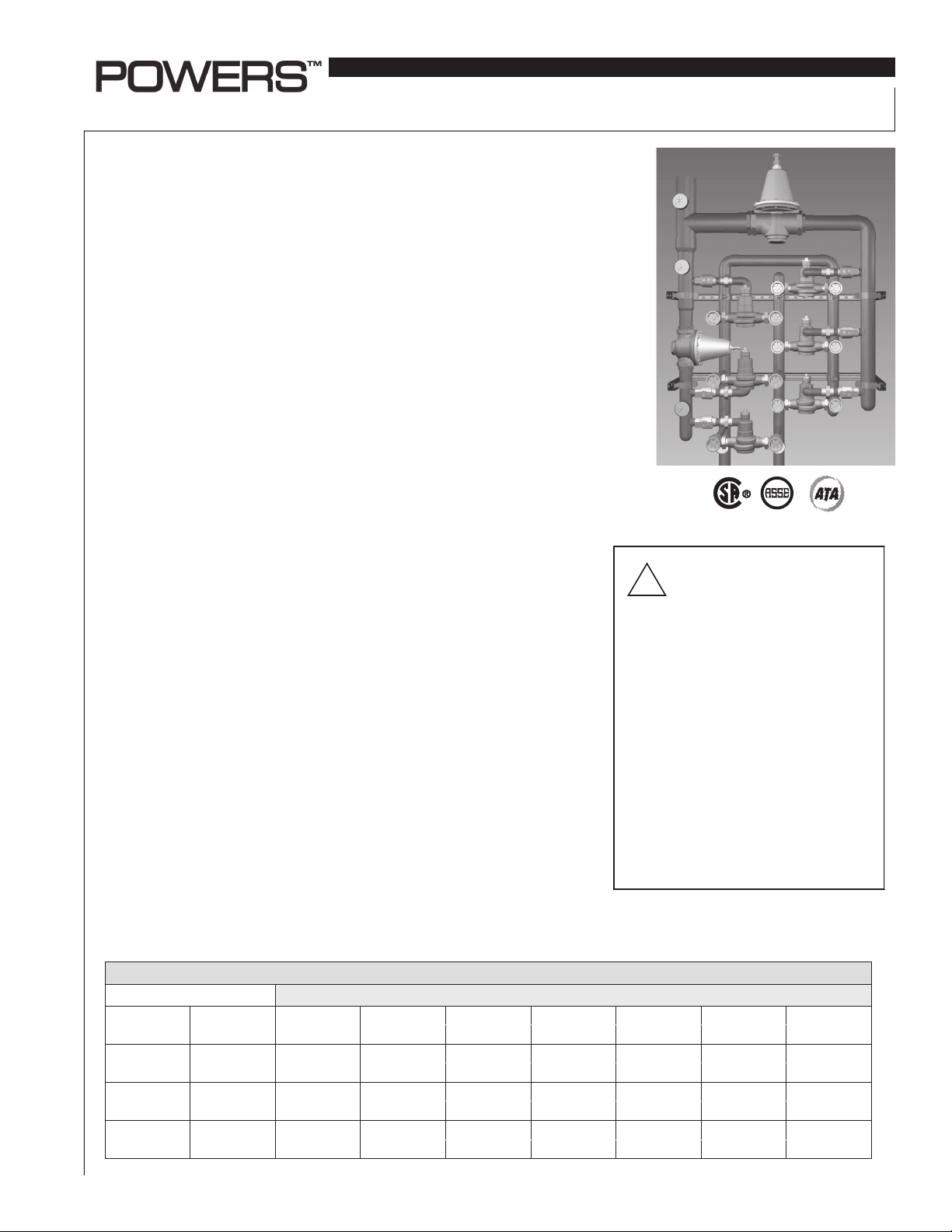
Powers' HydroGuard® XP Series SH1434 & LFSH1434 Triple, Quad and Six Valve
Hi/Lo's are fully assembled, factory tested systems, designed to provide safe
water throughout commercial and institutional facilities. Each consists of MM434
or LFMM434 and SH1434 or LFSH1434 Master Tempering Valves which utilize paraffin-based actuation technology to sense and adjust outlet temperature. Each
system includes a PRV, ball valves, pressure/temperature gauges and Powers'
triple-duty check stops and are supported by heavy-duty welded struts. Optional
equipment includes cabinets and/or Powers' AquaSentry® 2 high-temperature
alarm system. (Not available with LFSH1434 Series).
Operation n
The Triple, Quad and Six Valves Hi/Lo feature one low capacity valve that works in
parallel with multiple high capacity valves. During low demand, the low capacity
valve handles the load requirements. As the load demand increases, the pressure reducing valve, which is set at a certain pressure differential, will open and
allow flow through the high capacity valves to assist the low capacity valve in
meeting the increased load requirements.
IS-P-SF-SH1434-TV_QV_6V
Advanced Thermal Activation
Specifications n
Maximum Operating Pressure ............................. 125psi (861 kPa)
Maximum Hot Water Temperature ...................... 200°F (93°C)
Minimum Hot Water Supply Temp* .................... 5°F (3°C) Above Set Point
Hot Water Inlet Temperature Range ................... 120 -180°F (49 - 82°C)
Cold Water Inlet Temperature Range ................. 40 - 80°F (4 - 27°C)
Minimum Flow** ...................................................... 0.5 gpm (1.89 lpm)
Temp. Adjustment Range *** ............................... 90 - 160°F (32 - 71°C)
Listing/Compliance (Valve Only)............................ ASSE 1017, CSA B125
*With Equal Pressure
**Minimum flow when Hi/Lo valve is installed at or near hot water source recirculating tempered
water with a properly sized continuously operating recirculating pump.
***Note: Low limit cannot be less than the cold water temperature. For best operation, hot
water should be at least 5°F (3°C) above desired set point.
Table 1 Capacity n
Flow Capacity at 50-50 Mixed Ratio
Pressure Drop Across Valve
Model
SH1434TV and
LFSH1434TV
SH1434QV and
LFSH1434QV
SH1434-6V and
LFSH1434-6V
Min. Flow
to ASSE 1017
1 gpm
4 lpm 526 lpm 742 lpm 1049 lpm 1287 lpm 1575 lpm 1817 lpm
1 gpm
4 lpm 704 lpm 996 lpm 1412 lpm 1726 lpm 2116 lpm 2442 lpm
1 gpm
4 lpm 1067 lpm 1514 lpm 2139 lpm 2620 lpm 3206 lpm 3702 lpm
C
V
62.0
83.3
126.3
5psi 10psi 20psi 30psi 45psi 60psi
(34 kPa) (69 kPa) (138 kPa) (207 kPa) (310 kPa) (414 kPa)
139 gpm 196 gpm 277 gpm 340 gpm 416 gpm 480 gpm
186 gpm 263 gpm 373 gpm 456 gpm 559 gpm 645 gpm
282 gpm 400 gpm 565 gpm 692 gpm 847 gpm 978 gpm
WARNING: TO ENSURE THE
ACCURATE AND RELIABLE
!
OPERATION OF THIS PRODUCT, IT IS
ESSENTIAL TO:
• Properly size each valve based on the individual application.
• Properly design the recirculation system to
minimize pressure and temperature variations.
• Conduct an annual maintenance program to
ensure proper operation of all critical components.
THIS VALVE MUST BE USED IN
CONJUNCTION WITH TEMPERATURE
ACTUATED POINT-OF-USE DEVICES THAT
COMPLY WITH ASSE 1016, 1069, OR 1070.
FAILURE TO COMPLY WITH PROPER
INSTALLATION INSTRUCTIONS COULD
CONTRIBUTE TO VALVE FAILURE, RESULTING
IN IN JURY OR DEATH.
Page 2
Prior to Installation
SH1434
#1 - MM434
#2 - MM434
Screw
1. Flush all piping thoroughly before installing.
2. Make sure all ball valve handles are in "OFF" position.
3. In order to make any temperature adjustment to the valves,
you must open end-of-line fixtures to ensure you have adequate flow across the valve.
4. Use a thermometer at the showerhead or install an in-line
thermometer at the point-of-use.
SH1434TV & LFSH1434TV
1. Close the ball valve at the outlet of the SH1434 or LFSH1434
and MM434 or LFMM434 valve #2.
2. Open the ball valve at the outlet of the MM434 or LFMM434
valve #1.
3. Open enough fixtures to meet the minimum flow requirement
of the MM434 or LFMM434 valve #1 as per table 2.
4. Set MM434 or LFMM434 valve #1 temperature (refer to IS-PMM430 if required).
5. Close ball valve at the outlet of the MM434 or LFMM434 valve
#1 and open the ball valve at the outlet of the MM434 or
LFMM434 valve #2. Repeat steps 3 and 4.
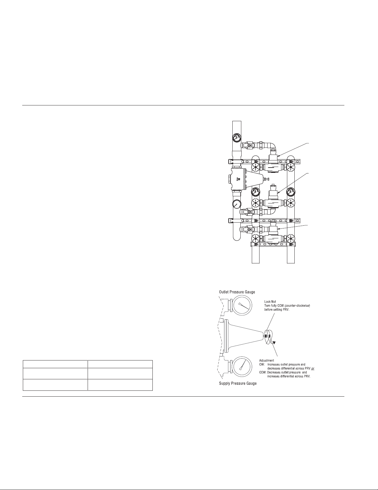
6. Loosen the locknut at the top of the PRV. This must be all the
way out or you will be limiting range of the adjustment.
7. Adjust the PRV so the outlet pressure gauge (top) reads 15psi
less than the supply pressure gauge (bottom). Turning the
adjustment screw counterclockwise will increase the differential across the PRV (allowing the PRV to open later).
8. Close the ball valve at the discharge of the MM434 or
LFMM434 valve #2.
9. Open the ball valve on the outlet of the SH1434 or LFSH1434
valve.
10. Open enough fixtures to meet the minimum flow requirement
of SH1434 or LFSH1434 as per table 2.
11. Set SH1434 or LFSH1434 temperature (refer to IS-P- SH1430
if required).
12. Open all the ball valves at the outlets.
13. Verify outlet temperature remains at the set point.
14. For any problem, refer to Troubleshooting section of the
document or contact Powers' Technical Support Department
at 1.800.669.5430 or info@powerscontrols.com.
Set Up Procedure nInstallation Instructions n
You must follow these procedures in order to properly adjust
your Hi/Lo System. You need flow greater than the minimum
shown in the capacity table across the valve in order to set a
maximum temperature.
SH1434 or
LFSH1434
#1 - MM434 or
LFMM434
#2 - MM434 or
LFMM434
Table 2
Model
MM434 and LFMM434 7 gpm (26 lpm)
SH1434 and LFSH1434 1 gpm (4 lpm)
Min. Flow to ASSE 1017
SH1434QV or LFSH1434QV
1. Close the ball valve at the outlet of the SH1434 or LFSH1434
and MM434 or LFMM434 valve #2 & #3.
2. Open the ball valve at the outlet of the MM434 valve #1.
3. Open enough fixtures to meet the minimum flow requirement
of the MM434 or LFMM434 valve #1 as per table 2.
4. Set MM434 or LFMM434 valve #1 temperature (refer to IS-PMM430 if required).
5. Close ball valve at the outlet of the MM434 or LFMM434 valve
#1 and open the ball valve at the outlet of the MM434 or
LFMM434 valve #2. Repeat steps 3 and 4.
6. Close ball valve at the outlet of the MM434 or LFMM434 valve
#2 and open the ball valve at the outlet of the MM434 or
LFMM434 valve #3. Repeat steps 3 and 4.
7. Loosen the locknut at the top of the PRV. This must be all the
way out or you will be limiting range of the adjustment.
2
Page 3

SH1434QV Continued
SH1434
#1 - MM434
#2 - MM434
#3 - MM434
SH1434
#1
#1 - MM434
#2 - MM434
#2
#3 - MM434
#4 - MM434
#5 - MM434
8. Adjust the PRV so the outlet pressure gauge (top) reads 15psi
less than the supply pressure gauge (bottom). Turning the
adjustment screw counterclockwise will increase the differential across the PRV (allowing the PRV to open later).
9. Close the ball valve at the discharge of the MM434 or
LFMM434 valve #3.
10. Open the ball valve on the outlet of the SH1434 or LFSH1434
valve.
11. Open enough fixtures to meet the minimum flow requirement
of SH1434 or LFSH1434 as per table.
12. Set SH1434 or LFSH1434 temperature (refer to IS-P- SH1430 if
required).
13. Open all the ball valves at the outlets.
14. Verify outlet temperature remains at the set point.
15. For any problem, refer to Troubleshooting section of the
document or contact Powers' Technical Support Department
at 1.800.669.5430 or info@powerscontrols.com.
SH1434-6V
1. Close the ball valve at the outlet of the SH1434 or LFSH1434
and MM434 or LFMM434 valve #2, #3, #4 and #5.
2. Open the ball valve at the outlet of the MM434 or LFMM434
valve #1.
3. Open enough fixtures to meet the minimum flow requirement
of the MM434 or LFMM434 valve #1 as per table 2.
4. Set MM434 or LFMM434 valve #1 temperature (refer to IS-PMM430 if required).
5. Close ball valve at the outlet of the MM434 or LFMM434 valve
#1 and open the ball valve at the outlet of the MM434 or
LFMM434 valve #2. Repeat steps 3 and 4.
6. Close ball valve at the outlet of the MM434 or LFMM434 valve
#2 and open the ball valve at the outlet of the MM434 or
LFMM434 valve #3. Repeat steps 3 and 4.
7. Close ball valve at the outlet of the MM434 or LFMM434 valve
#3 and open the ball valve at the outlet of the MM434 or
LFMM434 valve #4. Repeat steps 3 and 4.
8. Close ball valve at the outlet of the MM434 or LFMM434 valve
#4 and open the ball valve at the outlet of the MM434 or
LFMM434 valve #5. Repeat steps 3 and 4.
9. Loosen the locknut at the top of the PRV #2. This must be all
the way out or you will be limiting range of the adjustment.
10. Adjust the PRV #2 so the outlet pressure gauge (top) reads
20psi less than the supply pressure gauge (bottom). Turning
the adjustment screw counterclockwise will increase the differential across the PRV (allowing the PRV to open later).
11. Open the ball valve on the outlet of the MM434 or LFMM434
valve #1.
12. Close the ball valve at the discharge of the MM434 or
LFMM434 valve #5.
13. Loosen the locknut at the top of the PRV #1. This must be all
the way out or you will be limiting range of the adjustment.
14. Adjust the PRV #1 so the outlet pressure gauge (top) reads
15psi less than the supply pressure gauge (bottom). Turning
the adjustment screw counterclockwise will increase the differential across the PRV (allowing the PRV to open later).
SH1434 or
LFSH1434
#1 - MM434 or
LFMM434
SH1434 or
LFSH1434
#1
#1 - MM434
or LFMM434
#2 - MM434
or LFMM434
#3 - MM434 or
LFMM434
#2 - MM434 or
LFMM434
#2
#3 - MM434
or LFMM434
#4 - MM434
or LFMM434
#5 - MM434
or LFMM434
15. Open the ball valve on the outlet of the SH1434 or LFSH1434
valve.
16. Close the ball valve of MM434 or LFMM434 valve #1.
17. Open enough fixtures to meet the minimum flow requirement
of SH1434 or LFSH1434 as per table 2.
18. Set SH1434 temperature (refer to IS-P-SH1430 if required).
19. Open ball valves at the outlets of SH1434 or LFSH1434 and all
5 MM434 or LFMM434 valves.
20. Verify outlet temperature remains at the set point with all
valves open at a 15psi and 20psi differential.
21. For any problem, refer to Troubleshooting section of the
document or contact Powers' Technical Support Department
at 1.800.669.5430 or info@powerscontrols.com.
3
Page 4

Troubleshooting n
What to look for if:
• Outlet temperature is too hot with low ow:
1. The maximum temperature of the low flow valve was not
properly set. Refer to Set Up Procedure and reset the maximum temperature of the low flow valve.
2. The thermal actuator of the low flow valve is not working
properly. Replace thermal actuator.
• Outlet temperature is too hot with a high ow:
1. The maximum temperature of a high flow valve was not
properly set. Refer to Set Up Procedure and reset the maximum temperature of the high flow valve.
2. The thermal actuator of the high flow valve is not working
properly. Replace accordingly, see IS-P-MM430 enclosed.
• Outlet temperature too low with low and high ow:
1. The hot water temperature is too low. You must have a supply temperature of at least 5º F (3º C) higher than the set
temperature. Readjust the hot water supply.
2. The checkstops on the hot side of the valve are not fully
open, or may be stuck due to liming. Open and clean check
stops.
3. The temperature has not been set properly on the small
and/or large valve. Refer to Set Up Procedure and reset the
valves.
• Outlet ow drops off:
1. The differential across the PRV is set too high, so the
high flow valve begins controlling the system too late,
and starves the system. Refer the Set Up Procedure and
decrease the differential across PRV.
2. The checkstops on the high flow valves are not fully open or
are stuck due to liming. Open and clean checkstops
3. The system pressure varies by more than 50% of the inlet
supply pressure.
• Outlet temperature cycles between hot and cold:
1. The differential across the PRV is set too low, so the high
flow valve begins controlling the system too early, and
therefore cycles (hunt for the set point). Refer to the Set Up
Procedure and increase the differential across PRV.
2. The system pressure varies by more than 50% of the inlet
supply pressure.
Preventative Maintenance n
Thermostatic water mixing valves are control devices which
must be cleaned and maintained on a regular basis.
1. Before servicing checkstops or piping, turn off the water
upstream. At least every twelve (12) months, open up the
checkstops, and check for the free movement of the poppet.
2. Before servicing the valve, turn off the water supply
upstream or close the checkstops. To close the checkstops,
turn the adjusting screw clockwise.
3. When opening checkstops after servicing, turn adjusting
screw counterclockwise to fully open position. Then turn
adjusting screw 1/2 turn clockwise for final setting.
4. Every three (3) months, check the maximum temperature
adjustments.
5. Every twelve (12) months, remove the valve bonnets and
check the internal components for freedom of movement.
CAUTION:
Any changes in supply condition could effect the out-
let water temperature. Check and adjust the valves
accordingly to prevent injury to the users.
Part List For Valve n
See enclosed IS-P-MM430 and IS-P-SH1430.
NOTE: AFTER COMPLETING REPAIRS,
CHECK DISCHARGE TEMPERATURE.
!
RESET IF NECESSARY.
WARNING: FAILURE TO PERFORM THIS
OPERATION COULD RESULT IN UNSAFE
DISCHARGE TEMPERATURE, WHICH MAY
CAUSE INJURY OR DEATH.
Warranty n
The Seller warrants that the equipment manufactured by it and covered by this order or contract is free from defects in material and workmanship and, without
charge, equipment found to be defective in material or workmanship will be repaired, or at Seller’s option replaced F.O.B. original point of shipment, if written
notice of failure is received by Seller within one (1) year after date of shipment (unless specifically noted elsewhere), provided said equipment has been properly
installed, operated in accordance with the Seller’s instructions, and provided such defects are not due to abuse or decomposition by chemical or galvanic action.
THIS EXPRESS WARRANTY IS IN LIEU OF AND EXCLUDES ALL OTHER WARRANTIES, GUARANTEES, OR REPRESENTATIONS, EXPRESS OF IMPLIED. THERE ARE
NO IMPLIED WARRANTIES OF MERCHANTABILITY OR OF FITNESS FOR A PARTICULAR PURPOSE. The Seller assumes no responsibility for repairs made on the
Seller’s equipment unless done by the Seller’s authorized personnel, or by written authority from the Seller. The Seller makes no guarantee with respect to material
not manufactured by it.
A Watts Water Technologies Company
IS-P-SF-SH1434-TV_QV_6V 0931 EDP# 6512310 © 2009 Powers
USA: Phone: 1.800.669.5430 • Fax 1.847. 229.0526 • www.powerscontrols.com
Canada: Phone: 1.888.208.8927 • Fax 1.888. 479.2887 • www.powerscontrols.ca
 Loading...