

Page 1
Technical Instructions
!
WARNING
Read this Manual BEFORE using this equipment.
Failure to read and follow all safety and use infor-
mation can result in death, serious personal injury,
property damage, or damage to the equipment.
Keep this Manual for future reference.
!
WARNING
FAILURE TO COMPLY WITH PROPER INSTALLATION AND
MAINTENANCE INSTRUCTIONS COULD CONTRIBUTE TO THE
VALVE FAILURE.
This Hot Water Master Tempering Valves cannot be used for
tempering water temperature at fixtures. Severe bodily injury
(i.e., scalding or chilling) and/or death may result depending
upon system water pressure changes and/or supply water
temperature changes. ASSE standard 1016, 1069 or 1070 listed
devices should be used at fixtures to prevent possible injury.
These Hot Water Tempering Valves are designed to be
installed at or near the boiler or water heater. They are not
designed to compensate for system pressure fluctuations and
should not be used where ASSE standard 1016, 1069 or 1070
devices are required. These valves should never be used to
provide “anti-scald” or “anti-chill” service.
The components of the system must be of materials with a
construction capable of withstanding the high limit output temperatures of the water heating source.
!
WARNING
Need for Periodic Inspection and Yearly Maintenance:
Periodic inspection and yearly maintenance by a licensed contractor is required. Corrosive water conditions and/or unauthorized adjustments or repair could render the valve ineffective for
service intended. Regular checking and cleaning of the valve’s
internal components and check stops helps assure maximum
life and proper product function. Frequency of cleaning and
inspection depends upon local water conditions.
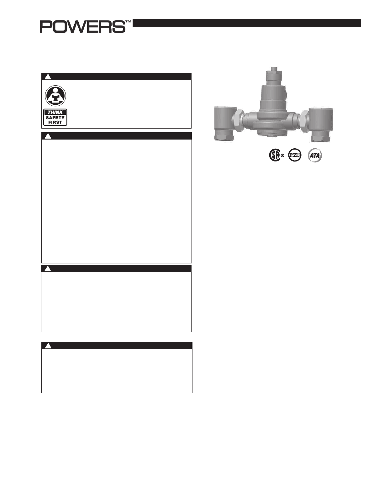
HydroGuard
Description
The HydroGuard® XP LFSH1430 series is a temperature actuated
mixing valve designed for use in hot water distribution systems, in
compliance with ASSE 1017.
Specifications n
Maximum Operating Pressure ...................... 125 psi (861 kPa)
Maximum Hot Water Temperature ............... 200°F (93°C)
Minimum Hot Water Supply Temp. .............. 5°F (3°C) Above Set-Point*
Hot Water Inlet Temperature Range ............ 120 -180°F (49 - 82°C)
Cold Water Inlet Temperature Range .......... 40 - 80°F (4 - 27°C)
Temp. Adjustment Ranges ** Standard: ....... 90 - 160°F (32 - 71°C)
Listing ........................................ ASSE 1017
IS-P-SH1430
®
XP Master Tempering Valves
Series LFSH1430
Advanced Thermal Actuation
n
Low: .................. 60 - 90°F (16 - 32°C)
!
WARNING
You are required to consult the local building and plumbing codes prior to installation. If the information in this
manual is not consistent with local building or plumbing
codes, the local codes should be followed. Inquire with
governing authorities for additional local requirements.
Certified .................................... CSA B125
* With Equal Pressure
** Low limit cannot be less than the cold water temperature.
For best operation, hot water should be at least 5°F (3°C) above
desired set point.
Page 2
Capacity n
Capacity Table, presents the HydroGuard discharge capacity in gpm
and lpm for various pressure drops across the valves (the difference
Flow Capacity at 50-50 mixed ratio
Model
LFSH1432
LFSH1434
LFSH1435
* Minimum flow when HydroGuard is installed at or near hot water source with recirculated tempered water with continuously operating recirculating pump.
Min. Flow Min. Flow
Rate* to ASSE 1017
0.5 gpm 1 gpm
1.89 lpm 4 lpm 72 lpm 102 lpm 144 lpm 178 lpm 216 lpm 250 lpm 269 lpm
0.5 gpm 1 gpm
1.89 lpm 4 lpm 159 lpm 227 lpm 322 lpm 394 lpm 481 lpm 556 lpm 602 lpm
0.5 gpm 5 gpm
1.89 lpm 19 lpm 254 lpm 360 lpm 507 lpm 621 lpm 761 lpm 878 lpm 950 lpm
C
V
8.54
19.00
30.00
5psi 10psi 20psi 30psi 45psi 60psi 70psi
(34 kPa) (69 kPa) (138 kPa) (207 kPa) (310 kPa) (414 kPa) (517 kPa)
19 gpm 27 gpm 38 gpm 47 gpm 57 gpm 66 gpm 71 gpm
42 gpm 60 gpm 85 gpm 104 gpm 127 gpm 147 gpm 159 gpm
67 gpm 95 gpm 134 gpm 164 gpm 201 gpm 232 gpm 251 gpm
between the lowest inlet pressure and the discharge pressure at the
HydroGuard.)
Pressure Drop Across Valve
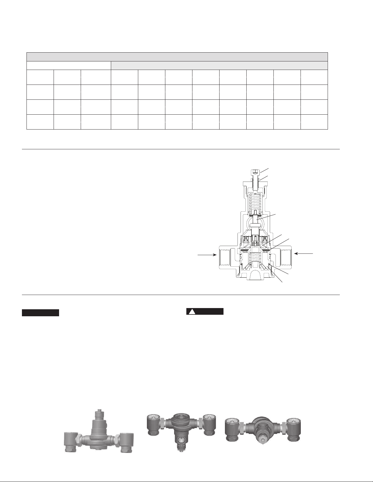
Operation n
Typical Flow
Hot and cold water supplies enter HydroGuard at indicated ports, (see
Figure 1) then flow past their respective seats. Next, hot and cold water
flow is directed to the mixing chamber where the thermostatic motor is
located.
Temperature Change
With a rise in discharge temperature due to pressure or temperature
fluctuation on the inlet, the actuator expands, decreasing flow of hot
water. The reverse occurs with a drop in discharge temperature.
Responses
Temperature adjustment screw moves the actuator to the desired
discharge temperature.
• Cold water supply failure – causes actuator to expand drastically
reducing the flow of hot water
• Hot water supply pressure failure – causes actuator to contract
drastically reducing the flow of cold water
*
When tested in accordance to conditions described in ASSE 1017.
*
.
*
.
Figure 1
Hot Water
Temperature Adjustment Screw
Temperature Adjustment Locknut
Actuator
Mixing Chamber
Cold Water Seat
Cold Water
Hot Water Seat
Plunger
Installation Instructions n
NOTICE
1. Installation should be in accordance with acceptable plumbing
practices. Flush all piping thoroughly before installation. Installation
and field adjustment are the responsibility of the installer.
2. Valves are to be installed as close to building inlet supply as
possible to prevent/minimize pressure fluctuations.
3. Valve body can be rotated to install in multiple positions due to
union inlets (see Figure 2). Make sure that union nuts are tightened
securely.
4. Connect inlets and outlet and check for leaks.
Figure 2
Back Outlet
!
CAUTION
5. When the HydroGuard supplies tempered water to self-closing and/
or solenoid valves, provide a shock absorber (Powers Part No. 460-
353) on the discharge line.
6. Before use, check discharge temperature. Reset if
necessary.
OPERATION CHECK:
After HydroGuard is installed, make certain the supply stop valves and
strainers are free of debris, clean and ready for operation by disassembling checkstops as shown in servicing.
Front Outlet
2
Top Outlet
Page 3

Parts List - LFSH1432, LFSH1434 n
Index Description
LFSH1432 LFSH1434
1 Checkstop Rebuild Kit LF390 800 LF390 801
2 Plunger Kit 390 802 390 803
3 Adjusting Screw 390 688 390 688
4 O-Ring 390 805 390 806
5 Actuator - Standard Temperature 390 807 390 809
6 Actuator - Low Temperature 390 808 390 810
7 Funnel Kit LF390 829 LF390 830
8 Locknut 1051117 1051117
3
8
Parts List - LFSH1435 n
Index Description
LFSH1435
1 Checkstop Rebuild Kit LF390 811
2 Plunger Kit 390 812
3 O-Ring 390 813
4 Actuator - Standard Temperature 390 814
1
5 Actuator - Low Temperature 390 815
6 Funnel Kit LF390 831
7 Adjusting Screw 390 688
8 Locknut 105 1117
7
8
5 & 6
7
1
2
4 & 5
4
6
2
3
3
Page 4

Maintenance and Troubleshooting n
What to look for if:
• The ow of water is less than desired...
a. Stop valves or supply to HydroGuard not fully open.
b. Clogged checkstop strainer screens.
c. Accumulation of lime deposits around valve seats.
d. Low supply pressures.
• The ow of water is completely shut off...
a. Stop valves or supply valves are completely closed.
b. Valves downstream from HydroGuard fully closed.
c. Loss of either hot or cold water supply pressure.
• Discharge temperature varies...
a. Very large restriction in outlet flow.
b. Very large drop in inlet pressure.
c. Very large fluctuation of hot water supply temperature.
d. Worn valve seats.
e. Minimum flow requirement not achieved.
f. Lime deposits around motor, poppets and/or seat.
Servicing n
NOTICE
Before disassembling, make certain both hot and cold water supplies
are shut off.
Checkstop Disassembly
1. Remove bonnet with socket wrench.
2. Lift out strainer screen.
3. Reassemble in reverse order.
Valve Disassembly
To Remove Thermal Actuator from Top
1. Loosen locknut.
2. Remove bonnet and pull out overload assembly by using
standard pliers.
3. Lift out thermal actuator by using a needle nose plier.
4. Reassemble in reverse order.
Temperature Adjustment n
Temperature setting for LFSH1430 Series Valves:
1. Turn off re-circulation pump (if one is in the system).
2. Open up enough fixtures to meet minimum flow requirement of:
LFSH1432 = 1 gpm (4 Lpm)
LFSH1434 = 1 gpm (4 Lpm)
LFSH1435 = 5 gpm (19 Lpm)
3. Loosen locknut (see Fig. 1)
4. Turn temperature adjusting screw counterclockwise to increase or
clockwise to decrease the outlet temperature. (see Fig. 1)
NOTICE
Please allow valve temperature to settle in before making your next
adjustment.
5. Temperature setting must be checked by an installer before
use. See temperature adjustment below.
To Remove The Plunger Assembly Or Funnel from Bottom
1. Remove the bottom cap.
!
CAUTION
Spring is under tension.
2. Pull out spring.
3. Pull out plunger using a pair of pliers.
4. To remove Funnel, you will need a deep socket wrench and funnel
removal tool.
5. Reassemble in reverse order.
6. Temperature setting must be checked by an installer before
use. See temperature adjustment below.
After reassembling go back to thermal actuator section and make sure
it is sitting in its holder properly.
5. When desired temperature is set, tighten the locknut. Turn
re-circulation pump back on. Close open fixtures.
!
WARNING
Any changes in supply condition could effect the outlet water temperature. Check and adjust the valves
accordingly to prevent injury to the users. After completing repairs, check discharge temperature, (105°F
[41°C]). Reset if necessary. Failure to perform this
operation could result in unsafe discharge temperature, which may cause injury or death.
WARNING: This product contains chemicals known to the
State of California to cause cancer and birth defects or
other reproductive harm.
For more information: www.watts.com/prop65
Warranty n
The Seller warrants that the equipment manufactured by it and covered by this order or contract is free from defects in material and workmanship and, without
charge, equipment found to be defective in material or workmanship will be repaired, or at Seller’s option replaced F.O.B. original point of shipment, if written
notice of failure is received by Seller within one (1) year after date of shipment (unless specifically noted elsewhere), provided said equipment has been properly
installed, operated in accordance with the Seller’s instructions, and provided such defects are not due to abuse or decomposition by chemical or galvanic action.
THIS EXPRESS WARRANTY IS IN LIEU OF AND EXCLUDES ALL OTHER WARRANTIES, GUARANTEES, OR REPRESENTATIONS, EXPRESS OF IMPLIED. THERE ARE
NO IMPLIED WARRANTIES OF MERCHANTABILITY OR OF FITNESS FOR A PARTICULAR PURPOSE. The Seller assumes no responsibility for repairs made on the
Seller’s equipment unless done by the Seller’s authorized personnel, or by written authority from the Seller. The Seller makes no guarantee with respect to material
not manufactured by it.
A Watts Water Technologies Company
IS-P-SH1430 1336 EDP# 6512307 © 2013 Powers
USA: Phone: 1.800.669.5430 • Fax 1.847. 229 .0526 • www.powerscontrols.com
Canada: Phone: 1.888.208.8927 • Fax 1.888.479.2887 • www.powerscontrols.ca
 Loading...