

Power Products Logic Energy User Manual
Advanced Modular Charging System
For Two-Way Radio Batteries
Thank you for purchasing a Logic Energy In-Vehicle Charger
(LEVC). This ultra-rugged product is designed for rapid charging two-way radio batteries in a vehicle, trailer, or train. LEVC
models are “radio specic,” but can charge batteries with: lithium
ion (Li-Ion), lithium polymer (LiPo), nickel-metal hydride (NiMH),
or nickel cadmium (NiCd) chemistry. Please review this manual
before installing or using the LEVC.
Important
1. Read the Caution section below and this User Manual before attempting to install the LEVC
or charge a battery.
Check to make sure the LEVC model is compatible with your radio and battery before installing.
2.
3.
Always charge new batteries completely before initial use. For best battery performance,
recharge NiCd and NiMH batteries when they are fully discharged. Recycle batteries when
they can no longer be used.
Caution
1. Never attempt charging alkaline or dry cell batteries with this charger. They may burst and
cause damage or personal injury.
Do not charge Li-Ion, LiPo, NiMH, or NiCd batteries unless they are designed with overcharge
2.
and overheat protection.
Do not discard unwanted batteries in the trash or incinerate. Batteries exposed to re or
3.
excessive heat may explode.
4. Install the LEVC inside a vehicle or protected area. Do not expose any components to rain,
liquids, or excessive moisture.
5. Make sure contacts on the radio holder and battery are clean. Do not allow wire or metal
objects to touch the contacts in the radio holder or any internal part of the charge controller.
6. Do not open the radio holder or remove the charge controller housing or make any modication to the LEVC.
7. Use only the DC power cable supplied with the LEVC.
8. Always secure the radio (or battery) in the radio holder with the tie-down strap before the
vehicle, trailer, or train goes in motion.
9. When replacing or adjusting the length of the tie-down strap, make sure that it will securely
hold the radio or battery, but that it is not too tight. If over-tensioned, the strap could cause
injury when released.
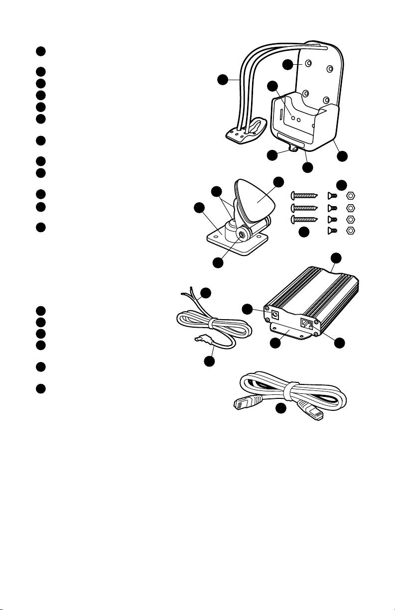
Radio Holder And Mount
1
Holes for fastening to multi-directional
mounting bracket
2
Connection point for interface cable
3
Status LED (illuminates orange, red, or green)
4
Hook for connecting tie-down strap
5
Tie-down strap
6
Charge contacts (number varies based
5
1
6
on LEVC model)
Mounting plate (with adhesive) for
7
attaching bracket to vehicle
8
Hinge adjustment bolt
9
Mounting plate for attaching bracket to radio
holder (universal AMPS 4-hole pattern)
10
Plate adjustment bolts
Bolts and locknuts for fastening radio
11
holder to mounting bracket
Screws for fastening mounting bracket
12
to vehicle
10
9
4
3
7
12
2
11
Note: If a heavy duty flat surface mount is
required, consider using RAM-B-101U. This RAM
mount has the universal AMPS hole pattern and
8
2
is compatible with the LEVC.
Charge Controller And Cables
Connection point for DC power cable
1
Integrated mounting brackets
2
Connection point for interface cable
3
DC power cable – plug this end into
4
5
1
2
3
charge controller
DC power cable – connect red to 12V or
5
24V source, black to ground
Controller to radio holder interface cable
6
with RJ45 connectors
4
6
Installing LEVC
1. Before installing the LEVC, conrm that the radio holder is compatible with the radio and
battery you want to charge.
2. Select an area in the vehicle to mount the radio holder. The slim prole of the LEVC allows
it to be installed in areas where traditional in-vehicle chargers will not t. Depending on
the location selected, you may be able to install the radio holder without using the multidirectional mount.
Select an area for mounting the charge controller. When choosing the location, keep in mind
3.
that the length of the DC power cable is 9.8’ (3.0 m) and the length of the interface cable is
6.6’ (2.0 m). If a longer interface cable is required, use a standard Ethernet cable with RJ45
connectors up to 13.1’ (4 m) in length.
If using the multi-directional mount, rst determine what adjustments to the mount are
4.
needed. The “hinge adjustment” allows the vertical position of radio holder to be changed.
Loosen slightly the bolt that passes through the hinge to adjust the angle of the radio holder
as needed; rmly tightened this bolt only after the mount and radio holder are installed.
5. The two “plate adjustment” bolts allow the radio holder to swivel left or right. Loosen these
 Loading...