

Power Products ALPHA C-20, ALPHA C-25 Operating Manual
www.power
-
products.com
ALPHA C-20/25
BATTERY CHARGER
OPERATING MANUAL
Power Products Inc. • 27 Pamaron Way, Suite E • Novato • CA 94949
Tel: (415) 883-6300 • Fax: (415) 883-6302
www.power-products.com

TABLE OF CONTENTS
1. SYSTEM OVERVIEW .................................................... 3
1.1 SYSTEM OVERVIEW ............................................................. 3
1.2 DISPLAYS AND CONTROLS................................................. 3
2. INSTALLATION............................................................. 6
2.1 LINE VOLTAGE ...................................................................... 6
2.2 TERMINALS............................................................................ 6
2.3 SPACE REQUIREMENTS ...................................................... 6
3. OPERATING GUIDE...................................................... 7
3.1 CHARGE CHARACTERISTICS.............................................. 7
3.2 CHARGING METHODS.......................................................... 8
3.3 PREPARATION FOR CHARGING ......................................... 9
3.4 VERIFY END VOLTAGE ...................................................... 10
3.5 CHARGE TIME ..................................................................... 11
4. CALIBRATION AND MAINTENANCE......................... 15
4.1 OVERVIEW OF CALIBRATION............................................ 15
4.2 SHUNT VERIFICATION........................................................ 16
4.5 OPERATING RANGES......................................................... 16
4.6 MAINTENANCE .................................................................... 17
5. TROUBLSHOOTING ................................................... 18
6. SPECIFICATIONS ....................................................... 19
APPENDIX A - BATTERY OVERVIEW............................. 20
CLASSES OF BATTERIES............................................................ 20
SECONDARY BATTERIES............................................................ 20
LEAD-ACID BATTERIES, VENTED OR SEALED (SLAB)............ 20
NICKEL-CADMIUM BATTERIES ................................................... 20
DEFINITIONS ................................................................................. 21
WARRANTY ..................................................................... 22
CERTIFICATION OF CALIBRATION................................ 23

1. SYSTEM OVERVIEW
1. SYSTEM OVERVIEW
1.1 SYSTEM OVERVIEW
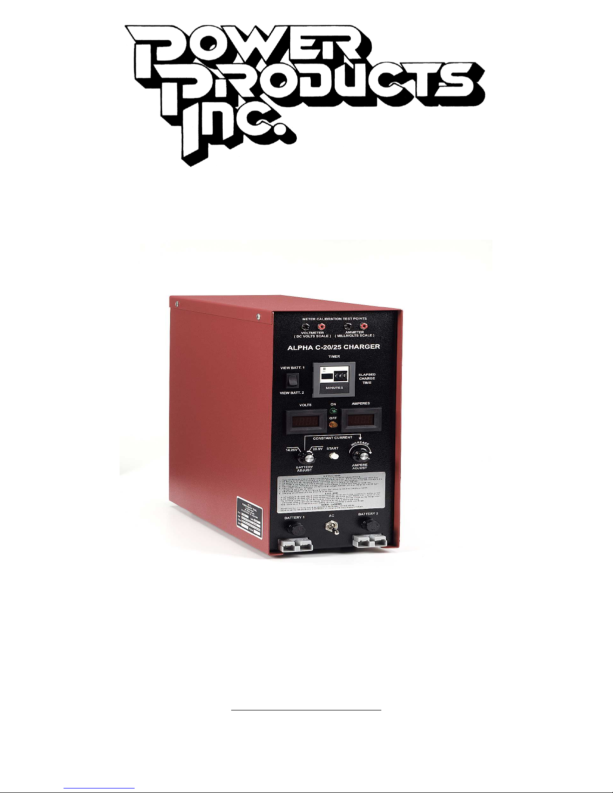
The Alpha C-25 Charger is a self-contained unit for charging of
rechargeable batteries. It has been designed to charge one or two batteries
of the same voltage rating simultaneously, to a combined maximum of 25
amperes. At a mere 40 lbs (18.2 kg) and 15 by 5 ¾ inches (381 by 146mm)
the C-25 takes minimal space and can easily be moved to add flexibility to
the work environment. The charger height and depth are the same as the
Power Products’ discharge tester, Beta D-50, with the same general
appearance. Therefore, two adjacent units comprise a charger/discharger,
which can service from one to three batteries simultaneously, lead-acid or
nickel cadmium.
The Alpha C-25 allows charging at both constant potential and constant
current to give flexibility in selection of charge method. The C-25 charger
has an adjustable charge current from 0 to 25 amperes. Two digital panel
meters allow viewing of charge current and voltage. They can be switched
to allow viewing of either of the two batteries being charged. A digital
electronic timer displays elapsed time and can be set to a fixed duration
charge period.
The flexibility of settings of the Alpha C-25 makes it usable for a wide variety
of batteries and voltages. The unit efficiently charges Lead Acid batteries of
12 or 24 volts, as well as Nickel Cadmium batteries of a single cell to 24
volts.
1.2 DISPLAYS AND CONTROLS
The Alpha C-25 has been designed to have very simple and easy to
understand controls and displays
ALPHA C-20/25 CHARGER – OPERATING MANUAL V1.0
(see figure 1-1 and 1-2).
Page 3
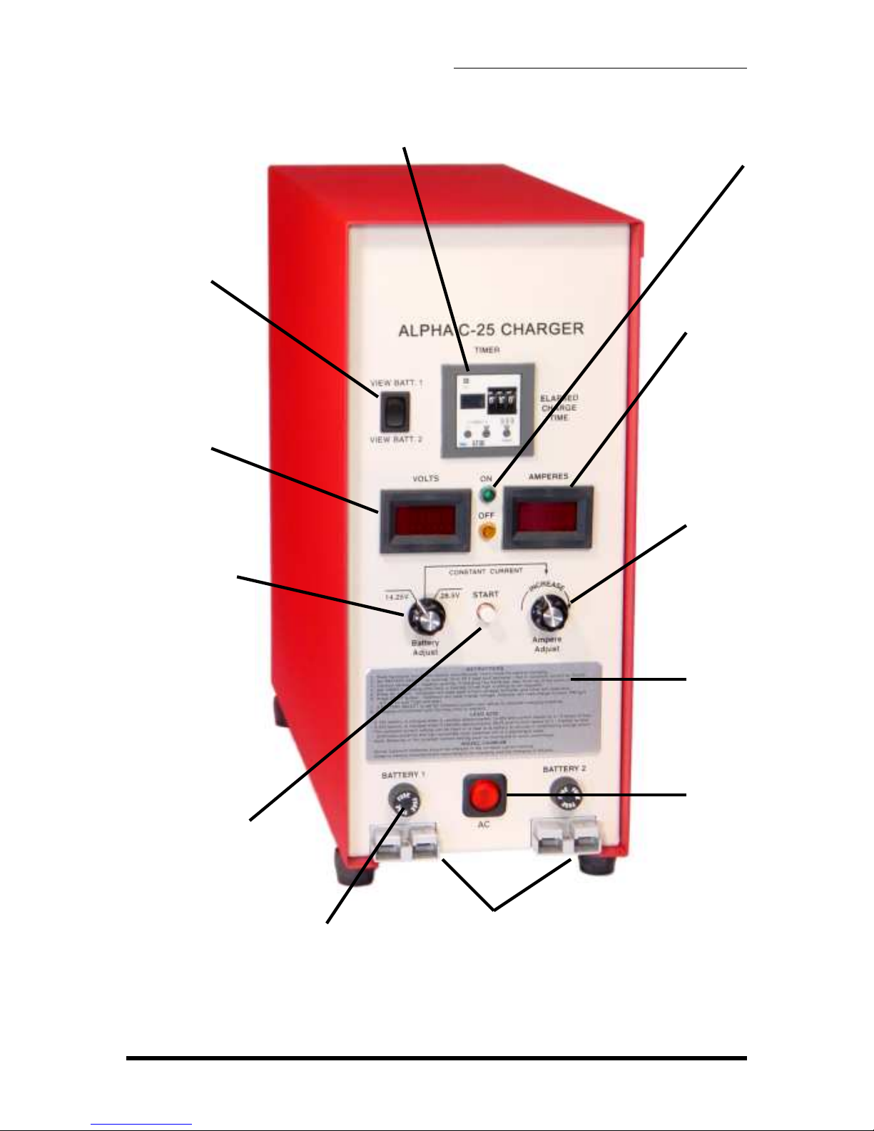
Fuse protecting
DC line
BATTERY VIEW
SWITCH
Switches between
displaying current
and voltage for
battery one or
battery two
DIGITAL
VOLTMETER
Displays battery
voltage during
charge
CHARGE MODE
SELECT KNOB
Selects constant current
or constant potential
mode for 12 or 24 volt
batteries
DIGITAL CHARGE TIMER
Displays elapsed charge
time.Can be set to fixed
duration charge times
1. SYSTEM OVERVIEW
ON/OFF LAMPS
Illuminate to indicate if
unit is charging (on) or
not (off)
DIGITAL AMMETER
Displays charge
current
AMPERE
ADJUST KNOB
Sets current
charge
INSTRUCTION
PANEL
START
BUTTON
Pressed to
start charge
DC LINE FUSE
ALPHA C-20/25 CHARGER – OPERATING MANUAL V1.0
DC LINE CONNECTORS
Connects for DC cable
leading to battery
Figure 1–1. Front view of Alpha C-25
Page 4
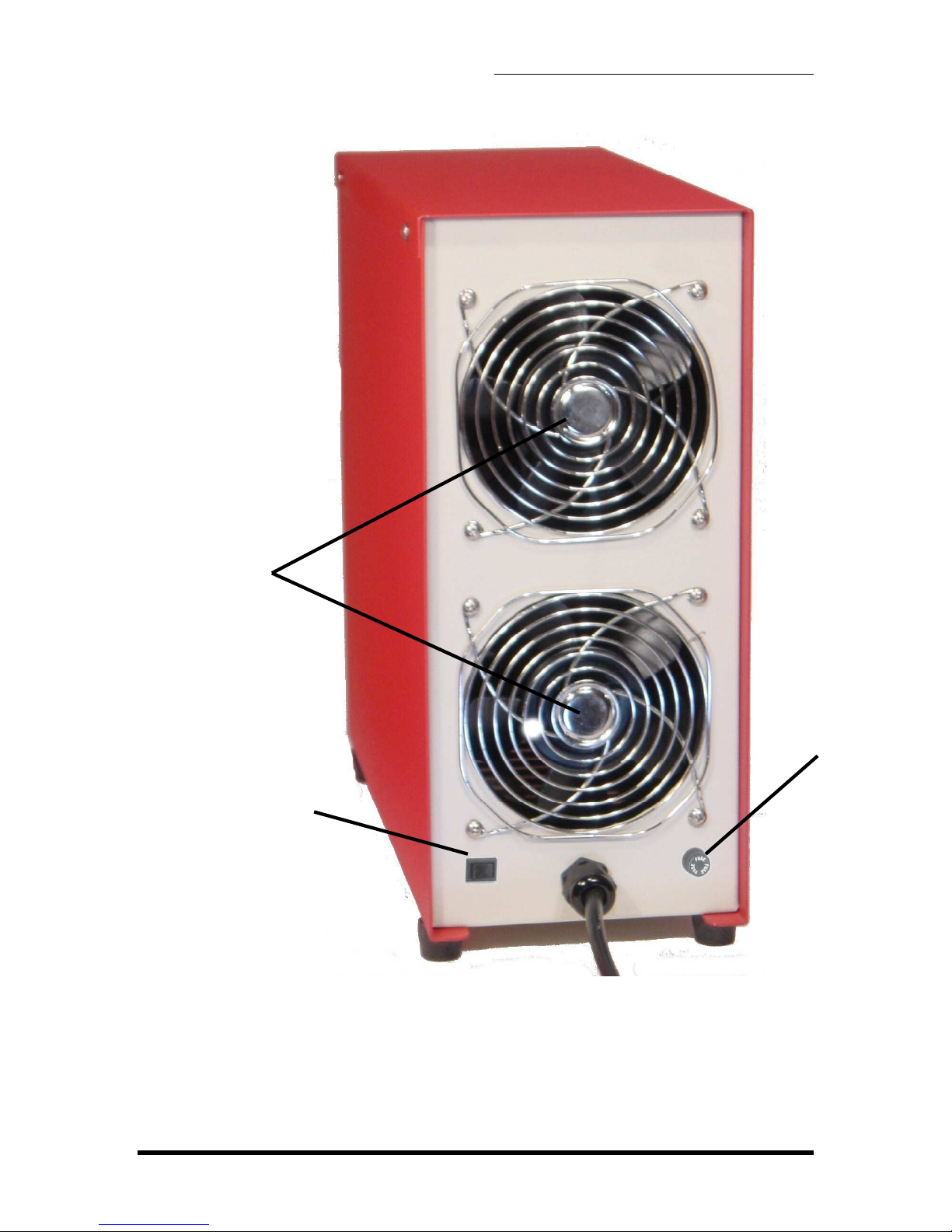
AC ON/OFF
SWITCH
Turns unit on
or off
1. SYSTEM OVERVIEW
COOLING FANS
AC MAINS CABLE
AC VOLTAGE
SELECT SWITCH
Selects mains input
voltage (115 or 230
volts)
AC LINE FUSE
Figure 1–2. Rear view of Alpha C-25
ALPHA C-20/25 CHARGER – OPERATING MANUAL V1.0
Page 5

2. INSTALLATION
2. INSTALLATION
2.1 LINE VOLTAGE
The Alpha C-25 can operate on either 115 and 230 Volts AC. The desired
line voltage can be selected on the rear of the unit.
CAUTION: Ensure that the unit is set for the appropriate
line voltage before operation.
A. On the back of the unit locate the AC voltage select switch.
B. Set switch for appropriately marked AC voltage (115 or 230 volts).
C. For 230 VAC operation, the 115 VAC plug must be replaced with one
for 230 VAC in required configuration.
NOTE: If the plug has to be changed make sure to connect
the green AC line wire to ground.
Connect the unit to a wall outlet with a 15-20 ampere capacity. Sharing of
the line with other equipment may result in erratic operation if other
equipment draws high pulse or surge currents.
NOTE: The Alpha C-25 will maintain its operational
integrity with line fluctuation less than ± 10%.
2.2 TERMINALS
The Alpha C-25 is supplied with two DC cables. One cable has an aircraft
battery quick-disconnect connector and one has ring terminals. If the quickdisconnect connector is removed, the ring terminals can be used to connect
to a post terminal battery, or be fitted to a different quick-disconnect
connector.
WARNING : Correct polarity must be observed.
2.3 SPACE REQUIREMENTS
The Alpha C-25 system occupies 15" x 5 ¾" (381 mm x 146 mm) of tabletop
space. Place the unit on a sturdy workbench in a well-ventilated battery
servicing area with the battery adjacent to it.
ALPHA C-20/25 CHARGER – OPERATING MANUAL V1.0
Page 6
2. INSTALLATION
The rear of the unit has air flow for cooling. Allow at least 6" (150 mm) of
separation from the wall and adjacent equipment in order to maintain proper
air flow.
NOTE: In non air-conditioned rooms it is recommended
that circulating or extracting fans be used to aid in the
removal of heated air.
NOTE: Operation in dusty or otherwise dirty air
environments will severely reduce the cooling capacity of
the fans and can lead to premature failure.
3. OPERATING GUIDE
This section gives an overview of how to charge a battery using the Alpha C-25. Always
refer to the battery manufacturers’ maintenance manual for their recommended
charging methods and settings.
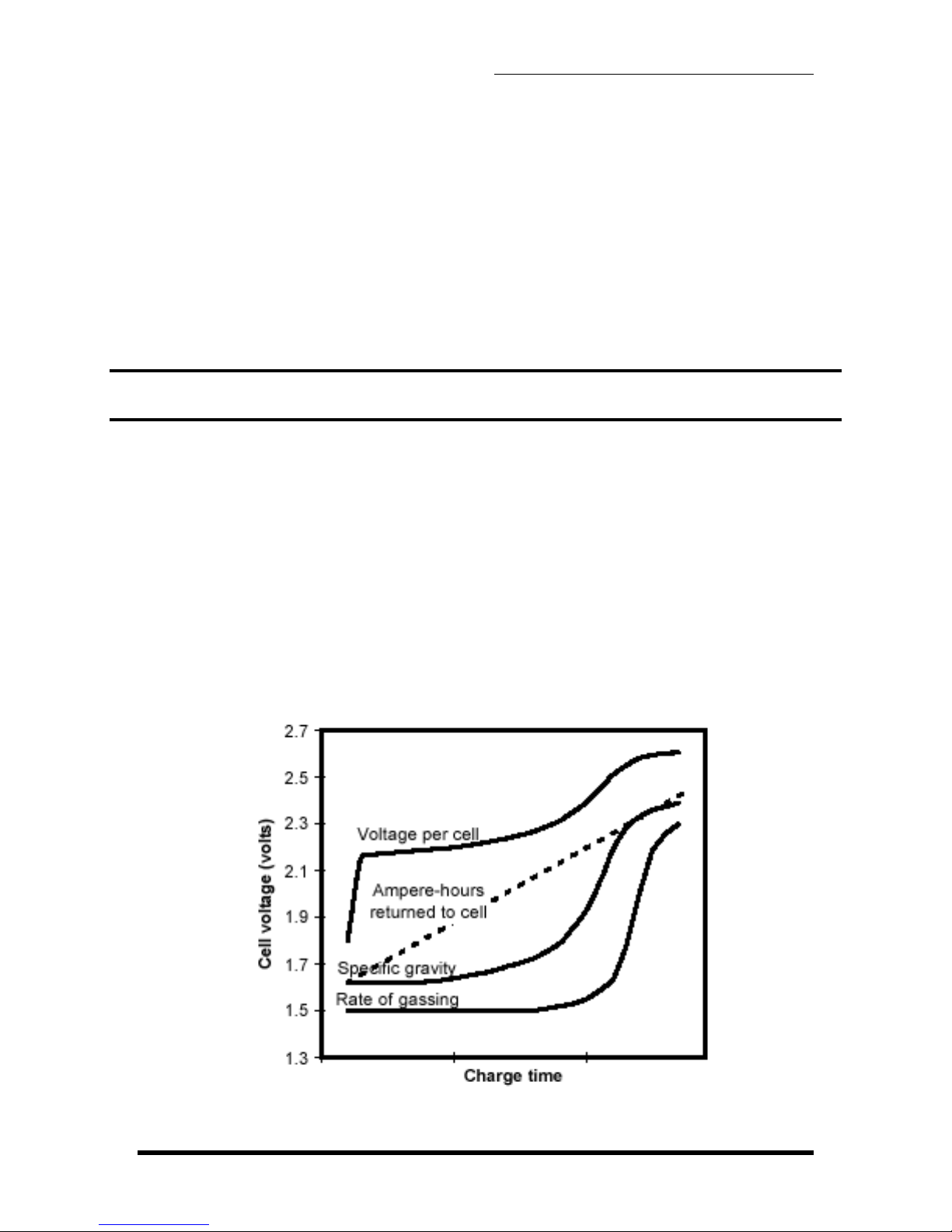
3.1 CHARGE CHARACTERISTICS
The constant current charge characteristics of a lead-acid cell with respect to cell
voltage, ampere-hours input, specific gravity and rate of gassing at constant
current can be seen in figure 3-1.
ALPHA C-20/25 CHARGER – OPERATING MANUAL V1.0
Page 7

3. OPERATING GUIDE
Figure 3-1. Charge characteristics of a lead-acid cell
As shown by the curve in figure 3-1 the cell voltage of a discharged battery rises
rapidly when the battery is first placed on charge. The extent of the initial rise
depends on the charging rate. As the charge continues, the voltage rises at a
slower rate and eventually levels off when a full state-of-charge is reached. It can
be seen that the specific gravity reading lags behind the rate of ampere-hour return
during most of the charging cycle. Consequently, the specific gravity is not
indicative of the available ampere-hour capacity until the cell approaches a fullcharge state.
When a battery reaches a full state-of-charge the voltage of the battery will
stabilize and remain constant or decrease. The charging should discontinue at this
stage. A minimum of 100% of previous discharge should be placed in the battery.
In general a vented battery may be charged at any rate that will not produce
excessive gassing or electrolyte temperatures above 115°F (46°C). Sealed leadacid batteries should never be charged in a constant-current mode with a current
greater than C
current charging at a rate in excess of C
/10 (C1 equals the rated capacity of the battery). During constant
1
/10, oxygen is produced at an excessive
1
rate. The resulting increasing pressure will cause the cell to vent. Venting of
gasses results in a depletion of electrolyte. As the electrolyte cannot be replaced in
a sealed battery, the cell will dry out resulting in a decrease in capacity and
eventually battery failure. Therefore constant-potential charging is the
recommended charge method for sealed batteries (SLAB).
3.2 CHARGING METHODS
There are two main methods of charging a battery:
1) constant current
2) constant potential.
In what follows both methods will be described in some detail.
3.2.1 CONSTANT-CURRENT CHARGE METHOD
In this method the current remains at a preset level while the voltage can reach a
high level, e.g. 34-37 volts.
An advantage of the constant-current charge method is that the ampere-hour input
into the battery can be determined precisely by multiplying the charging current
with the charge time in hours. However, it is necessary to ensure that the battery is
not charged at a high rate for an excessive period of time. Such overcharging can
result in overheating, excessive gassing, and possible damage to the battery.
ALPHA C-20/25 CHARGER – OPERATING MANUAL V1.0
Page 8
 Loading...