

Page 1
INSTALLATION MANUAL
Power-Pole® Signature Series
Shallow Water Anchor
Installation Instructions
CAUTION: Read this instruction manual carefully. Become
familiar with the controls and know how to operate the
Power-Pole
shallow water anchor system safely.
US Pat No. 6,041,730
Page 2

CONGRATULATIONS on your purchase
of a Power-Pole
Signature Series shallow
water anchor featuring C-Monster Control
System. It has been designed, engineered,
and manufactured to provide the best possible
performance and dependability for years of
enjoyment.
Please read all installation instructions carefully.
The information contained here describes the
proper procedures for safely installing your
Power-Pole shallow water anchor.
CAUTION:
Do not use the Power-Pole shallow water
anchor as your primary anchorage. Never
leave your boat unattended while anchored
solely with the Power-Pole shallow water anchor.
Page 3
Step 1: Choose a Mounting Location
Transom mounting
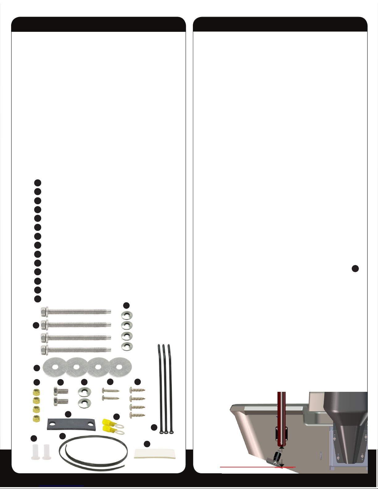
VERTICAL POSITIONING
1. Place a straight edge on the bottom of the hull directly
below and centered from the desired mounting
location. The lowest point of the Power-Pole anchor
must be at least 4” above this straight edge.
Note: If the Power-Pole anchor is mounted lower than
the 4” minimum, the vessel may experience adverse
handling effects. (See Figure #1)
CLEARANCE
1. If the vessel is equipped with trim tabs that measure 9”
or less in length, the standard 4” minimum mounting
height will be sufficient. If the trim tabs are larger than
9”, the Power-Pole anchor will need to be mounted
higher up on the transom to prevent interference.
2. While holding the Power-Pole anchor in place, turn and
tilt the motor as far as possible toward the unit. With
the motor turned toward the unit, manually move the
anchor through its entire range of motion to verify
clearance.
3. Once clearance has been verified on the exterior
portion of the vessel, check for adequate space on the
inside of the transom mounting area. Make sure that
the bolts will not have any obstructions, and that you
will have space to tighten the 5/16” tall brass nuts
D
.
Adapter plate mounting
1. If there is no suitable mounting location on the
transom, your vessel will require an adapter plate. We
offer adapter plates to accommodate a wide variety
of applications. Please contact one of our authorized
dealers or a member of our sales staff for an adapter
plate recommendation: (813) 689-9932 option 1
2. All adapter plates are accompanied by installation
instructions. Refer to the included instructions while
installing the adapter plate as well as the Power-Pole
anchor. Please contact our technical support team
with any questions: (813) 689-9932 option 2
J
K
A
B
C
D
E
F
G
H
i
L
M
N
4”
Figure 1
L
K
A
B
C
D
E
J
i
F
G
H
M
N
Installation Tools & Hardware
Installation Tools
• 1/2” & 9/16” wrenches
• 1/2” & 9/16” sockets with ratchet
• Electric or battery operated drill
• 7/64”, 9/64”, 5/16”, & 11/32” drill bits
• #2 Phillips-head bit or screwdriver
• Small slotted (flat-headed) screwdriver
• Heat gun
• 4’ foot straight edge
• Marine grade sealant
• Fine point marker
• Tape measure
• Wire cutters
• Wire strippers
• Wire terminal crimpers
• Razor tubing cutter or utility razor blade
• Small funnel
Installation Hardware
Qty(4) 5/16” x 3.5” all-thread transom mount bolts
Qty(4) 5/16” neo-bond washers
Qty(4) 5/16” fender washers
Qty(4) 5/16” tall brass nuts
Qty(2) 3/8” x 3/4” bolts
Qty(2) 3/8” neo-bond washers
Qty(2) #6 x 1/2” pan head screws
Qty(4) #10 x 3/4” pan head screws
Qty(1) rubber pump gasket
Qty(2) ring connectors
Qty(2) thru-hull bushings
Qty(3) marine cable ties
Qty(1) 5’ black mesh tubing cover
Qty(1) adhesive strip
Page 4
Step 2: Mounting the Power-Pole
®
1. Once the mounting location has been selected, place
the stern bracket against the transom, and mark the
mounting holes with a fine point marker. Carefully
drill pilot holes in each of the four marked locations
with a 9/64” drill bit. Then, drill out each of the four
pilot holes with a 5/16” drill bit.
2. Once all of the holes have been drilled, apply a liberal
amount of marine grade sealant between the stern
bracket and the hull, as well as around the 5/16”
holes.
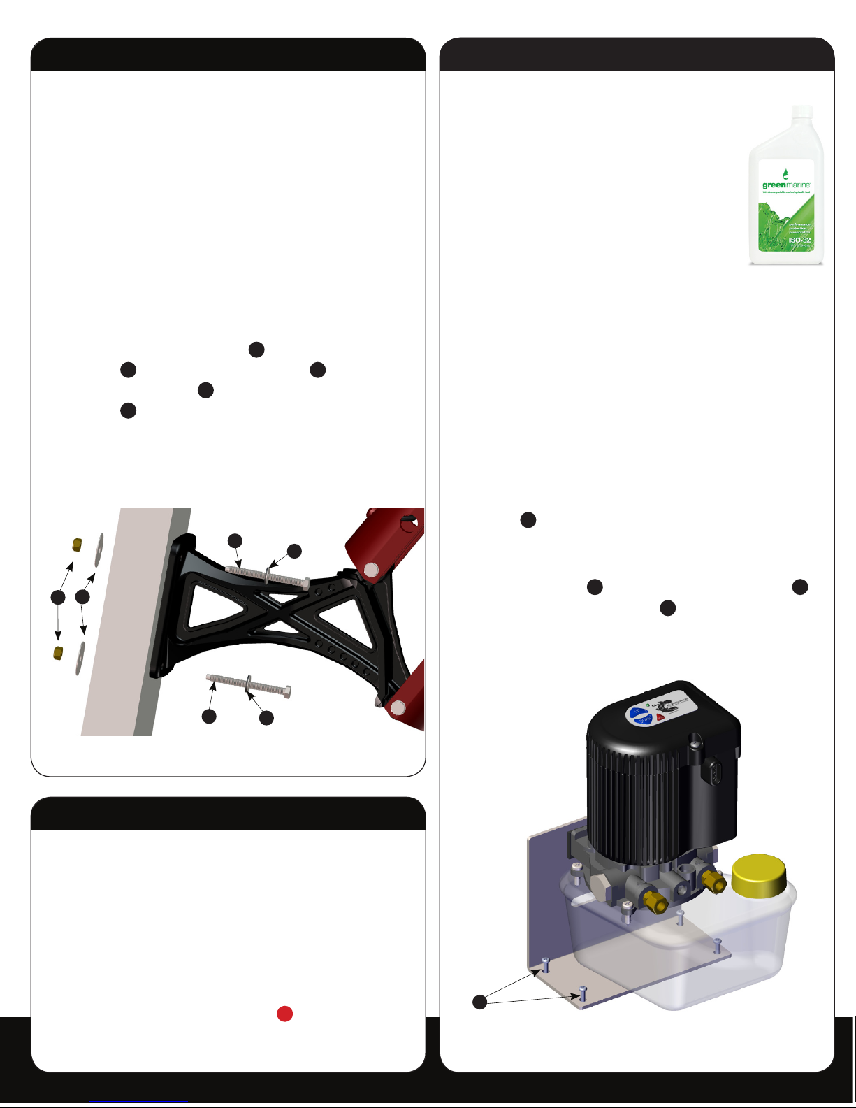
3. With a 1/2” wrench and 1/2” socket, fasten the stern
bracket to the transom using (4) 5/16” x 3.5” allthread transom mount bolts
A
, (4) 5/16” neo-bond
washers
B
, (4) 5/16” fender washers C, and (4)
5/16” tall brass nuts
D
. The rubber backed neo-bond
washers
B
will protect the powder coated surface of
the stern bracket, and they must not be over tightened.
(See Figure #2)
Step 3: Hydraulic Pump Unit (HPU)
Choose a mounting location
1. Locate a dry compartment in the vessel with ample
space to accommodate the HPU. The footprint of the
HPU is approximately 6.5”x 7”.
Note: Be sure to allow enough clearance
surrounding the HPU such that the hydraulic
tubing will not make a severe bend when exiting
the compartment. Also, allow enough space to
install the (2) 3/8” x 3/4” bolts
E
through the
mounting bracket and into the HPU.
A
A
B
B
C
D
Step 4: Installing the HPU
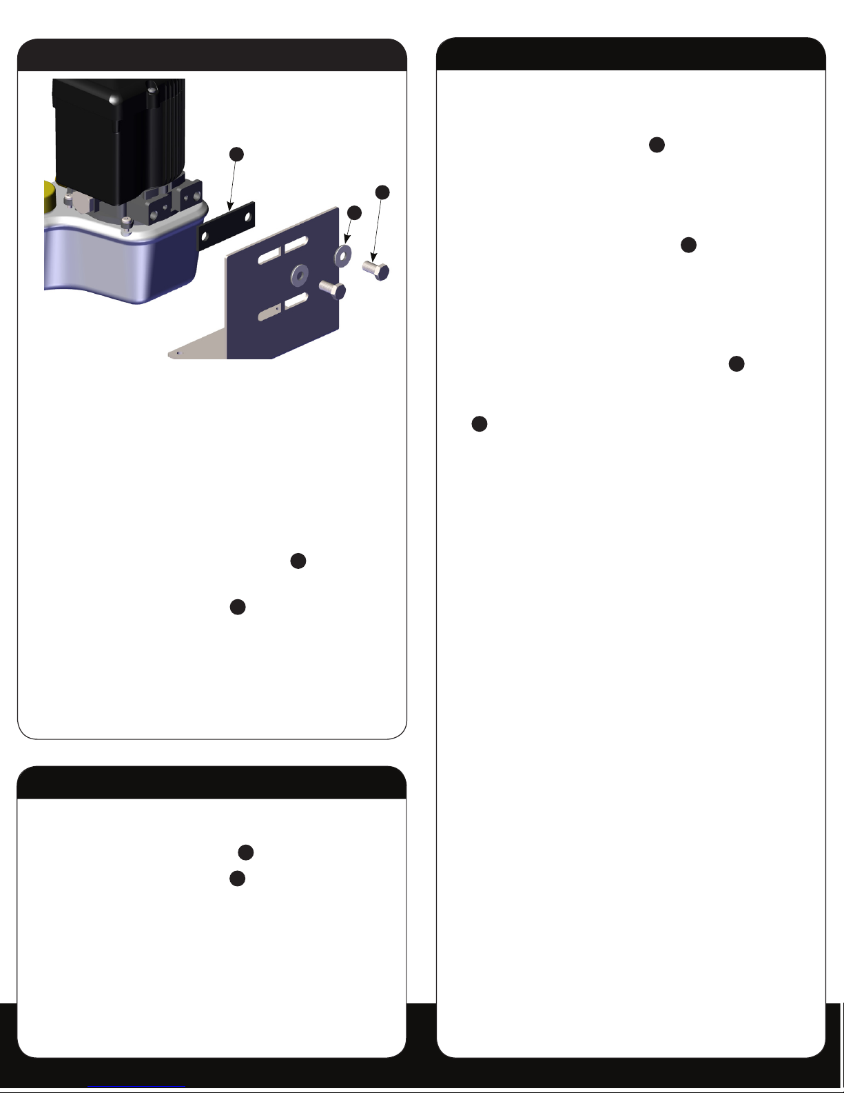
1. Remove the fill cap on the HPU, and fill the reservoir
to the “full” line with the supplied quart of
Green Marine
®
biodegradable hydraulic
fluid or an ISO 32 hydraulic fluid.
Using anything other than an ISO 32
hydraulic fluid, such as Green Marine,
may cause damage to the HPU, and will
void your warranty.
2. Place the HPU bracket in the
predetermined area of the vessel, and
inscribe the four mounting hole locations with a fine
point marker.
Before drilling holes to mount the HPU mounting
bracket, inspect the area beneath the mounting
surface to insure that the drill bit will not cause any
damage.
3. Using a 9/64” drill bit, carefully drill holes in the newly
inscribed locations.
4. Fasten the bracket to the vessel using a #2 Phillipshead screwdriver and the (4) #10 x 3/4” pan head
screws
H
.
5. Once the bracket is securely fastened, use a 9/16”
wrench to attach the HPU to its bracket using the (2)
3/8” x 3/4” bolts
E
, (2) 3/8” neo-bond washers F,
and (1) rubber pump gasket
i
.
(See Figure #3 and 4)
Figure 2
H
Figure 3.1
Page 5
Step 5: Installing Hydraulic Tubing
1. Guide the blue and black hydraulic tubing through
the black mesh tubing cover
M
.
Note: The black mesh tubing
M
cover may need to
be trimmed to length.
WARNING: Keep debris out of the hydraulic tubing.
Use the red end caps provided at all times while
routing the hydraulic tubing throughout the boat.
Debris in the tubing will cause damage to the HPU.
Step 5: Continued
2. At this point, the hydraulic tubing may be routed
in one of two ways. It may be routed either over
the transom or through the transom using the (2)
supplied thru-hull bushings
K
. If the hydraulic tubing
is not being installed through the transom, route
the tubing to the HPU as per your preference, and
proceed to Step E. If the hydraulic tubing is to be
installed through the transom, holes will need to be
drilled for the thru-hull bushings
K
.
Note: When choosing a location for the holes, ensure
that the tubing will form a natural curve when
leaving the stern bracket, and that the transom
holes will be above the water line.
3. First, drill pilot holes in the transom with a 9/64” drill
bit for each of the (2) thru-hull bushings
K
. Then,
drill out both pilot holes with an 11/32” drill bit. Once
the holes are drilled, insert the (2) thru-hull bushings
K
, and route the tubing to the HPU. (See Figure #4)
Note: Be sure to allow an adequate amount of slack in
the hydraulic tubing between the stern bracket and
the point that the tubing enters the vessel. This will
provide slack in the hydraulic lines to allow for full
up and down operation.
4. The tubing is now ready to be attached to the HPU.
Route the tubing according to your preference, and
trim the excess using a razor tubing cutter. All cuts
made in the tubing must be as straight as possible to
ensure that the compression fittings do not leak.
Note: For ease of future maintenance, leave enough
excess hydraulic tubing such that the HPU can be
moved out of the compartment with the tubing still
attached.
5. While taking note of their orientation, remove the blue
and black dust caps from the hydraulic compression
fittings on the HPU.
6. Disassemble both of the compression fittings by
removing their nuts and ferrules. With both the
blue and black hydraulic tubing cut to length, feed
each through a compression fitting nut as well as a
compression fitting ferrule. (See Figure #5)
Note: The tubing needs to pass through the ferrule far
enough such that there is approximately a
1/2” length of tubing exposed. (See Figure #5)
Step 4: Continued
6. Unravel the red and black wires on the HPU. Route
the red wire to a 12 volt positive source via a battery
switch, and route the black wire to a 12 volt negative
source via a common ground post.
Prior to cutting the excess wire, ensure that there is an
adequate amount of slack such that they may be
easily disconnected in the future.
7. Once the wires have been trimmed to length with wire
cutters, install the (2) ring connectors
J
using wire
strippers and wire terminal crimpers.
8. Heat the (2) ring connectors
J
with a heat gun until
their respective jackets shrink completely and adhere
to the wires.
DO NOT CONNECT the red or black wire at this time.
These wires will be connected once the hydraulic
tubing is installed.
E
i
F
Figure 4
Page 6
3. Once the unit has reached the end of its range of
motion, keep the “down” button depressed for 5
seconds in order to bleed all residual air from the
hydraulic tubing. Next, retract the anchor with the
“up” button. Once again, keep the button depressed
for 5 seconds in order to bleed all residual air from
the hydraulic tubing. Repeat this process three times
in both directions or until satisfactory performance is
achieved.
4. The HPU’s hydraulic fluid level may need to be toppedoff after the final priming has been completed.
Step 5: Continued
7. Insert the blue tubing into the compression fitting
labeled UP (blue dust cap), and the black tubing
into the fitting labeled DN (black dust cap). While
holding the blue tubing fully inserted into its
respective compression fitting base, begin threading
the compression fitting nut onto the base. Repeat this
step for the black tubing. (See Figure #6)
8. Tighten both compression fitting nuts with a 9/16”
wrench while simultaneously holding their respective
bases with a 1/2” wrench. (See Figure #7)
Warning: The nuts must be tightened down far
enough such that none of the compression
fitting’s threads are visible; otherwise, hydraulic
failure may occur. (See Figure #8)
Step 6: Priming the HPU
1. Now connect the red and black wires from the HPU
to their respective locations. See Step 4. Once both
wires are securely fastened, the green LED on the
HPU should flash indicating that the unit has power.
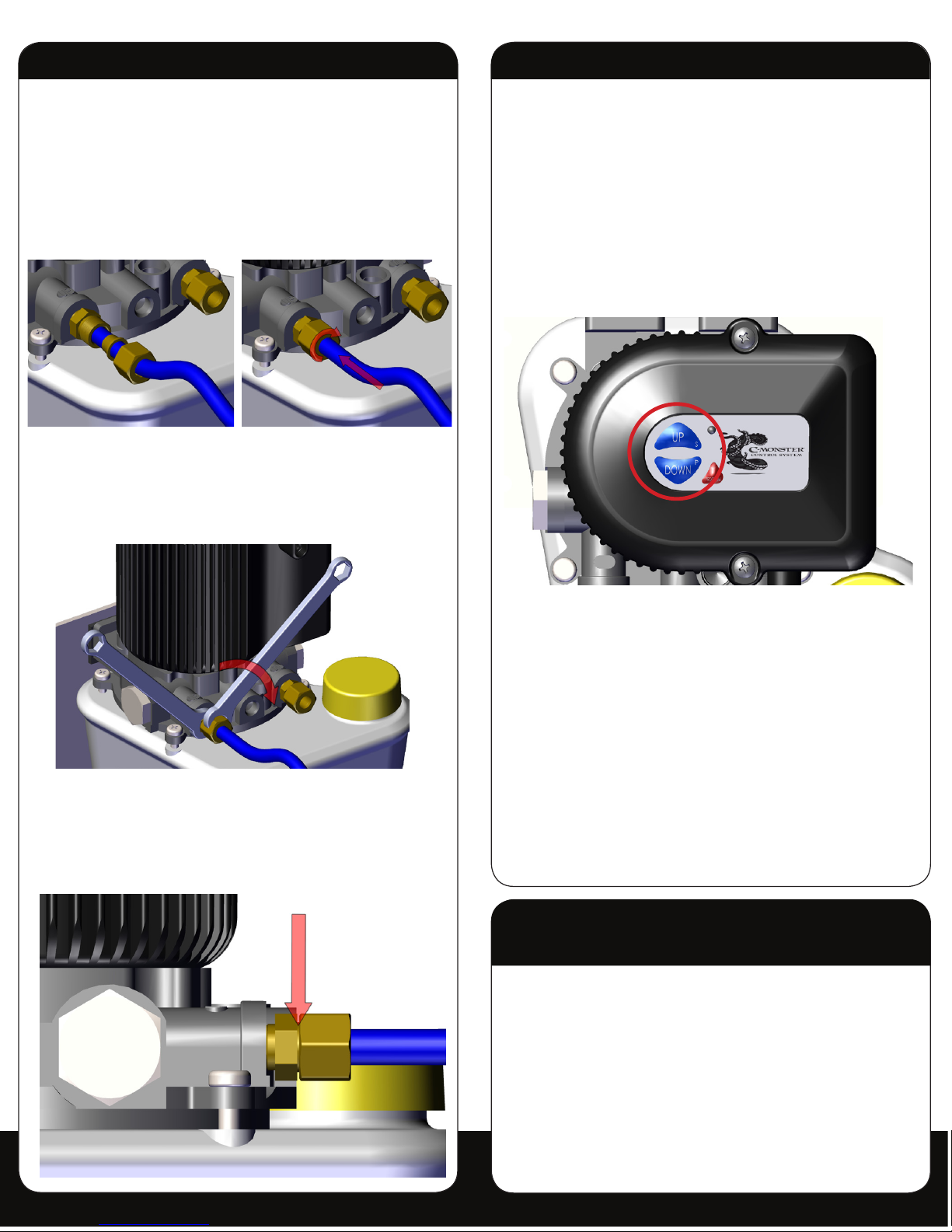
2. Use the “down” button on the HPU cover to cycle the
Power-Pole anchor from the fully retracted position to
the point where it makes contact with a solid surface.
(See Figure #9)
Figure 5 Figure 6
Figure 7
Figure 8
Figure 9
Step 7: Pairing the Dash Switch
and Remote Control
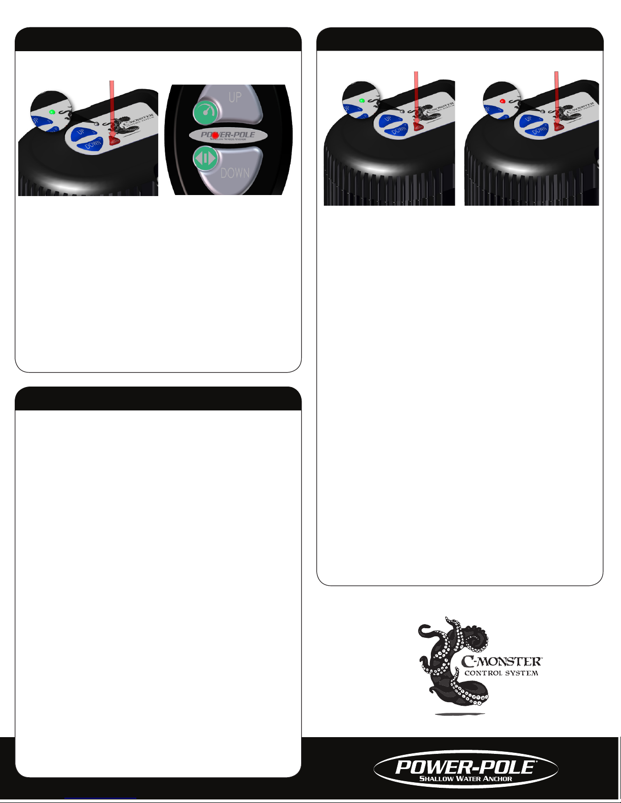
1. Locate the “program” button on the top of the pump
unit, depress and hold it for 3 seconds until the LED
steadily illuminates green in color. The pump unit is
now ready to be paired with the switch. The HPU will
remain in the pairing mode for 20 seconds.
(See Figure #10)
Note: When dual Power-Pole shallow water anchors
are installed, this procedure should be performed
on BOTH pump units.
Page 7
Step 8: Programming the HPU/HPUs
In order to utilize the full potential of the Power-Pole
shallow water anchor, the HPU/HPUs must be assigned
as either a single, port side, or starboard side unit.
Follow the “single unit” instructions when installing only
one anchor, and use the “dual units” instructions when
installing two anchors. The “dual units” instructions must
also be used when installing a second unit at a later date.
Note: Assigning a single unit as either a port side
or starboard side unit will cause adverse
operating behavior.
SINGLE UNIT
1. Locate the “program” button on the top of the HPU,
and depress and hold it for 6 seconds until the LED
steadily illuminates red in color. The LED will initially
illuminate green (after 3 seconds), but will change
to red after 6 seconds, thus indicating that the unit is
ready to be programmed. (See Figure #12)
2. Next, depress and hold both the “up” and the “down”
buttons on the HPU simultaneously. The LED will flash
red 3 times indicating that the programming has
been completed successfully.
Step 7: Continued
2. Next, depress and release the button on the remote
1 time. The green LED on the pump unit will initially
turn off, and then it will flash steadily indicating that
the pairing has been completed. (See Figure #11)
3. The surface mount switch is now paired to the pump
unit. Test its functionality by following the operating
instructions to ensure that the pairing procedure was
completed successfully.
4. Repeat the same programming procedure with the
remote control. (See Figure #10)
Step 8: Continued
DUAL UNITS
1. Using the “up” and “down” buttons on both HPUs,
determine which HPU controls the port side PowerPole anchor and which one controls the starboard
side. (See Figure #12)
2. With both HPUs identified, begin with the starboard
side unit. Locate the “program” button on the top of
the HPU, and depress and hold it for 6 seconds until
the LED steadily illuminates red in color. The LED will
initially illuminate green (after 3 seconds), but will
change to red after 6 seconds, thus indicating that the
unit is ready to be programmed.
3. Next, depress and hold the “up” button on the
starboard side HPU. The LED will flash red 2 times
indicating that the programming has been
completed
successfully, and the HPU has been assigned as the
starboard side unit.
4. Repeat the programming procedure with the port side
HPU, but instead depress and hold the “down” button
on the HPU. This time the LED will flash red 1 time
indicating that the programming has been completed
successfully, and the HPU has been assigned as the
port side unit.
Figure 10 Figure 11
Figure 12
Page 8
9208 Palm River Road, Suite 303, Tampa, Florida 33619
Phone 813-689-9932 Fax 813-689-8883
www.power-pole.com
Step 9: Installing the Dash Switch
1. Locate a suitable area with a flat surface to mount
the dash switch.
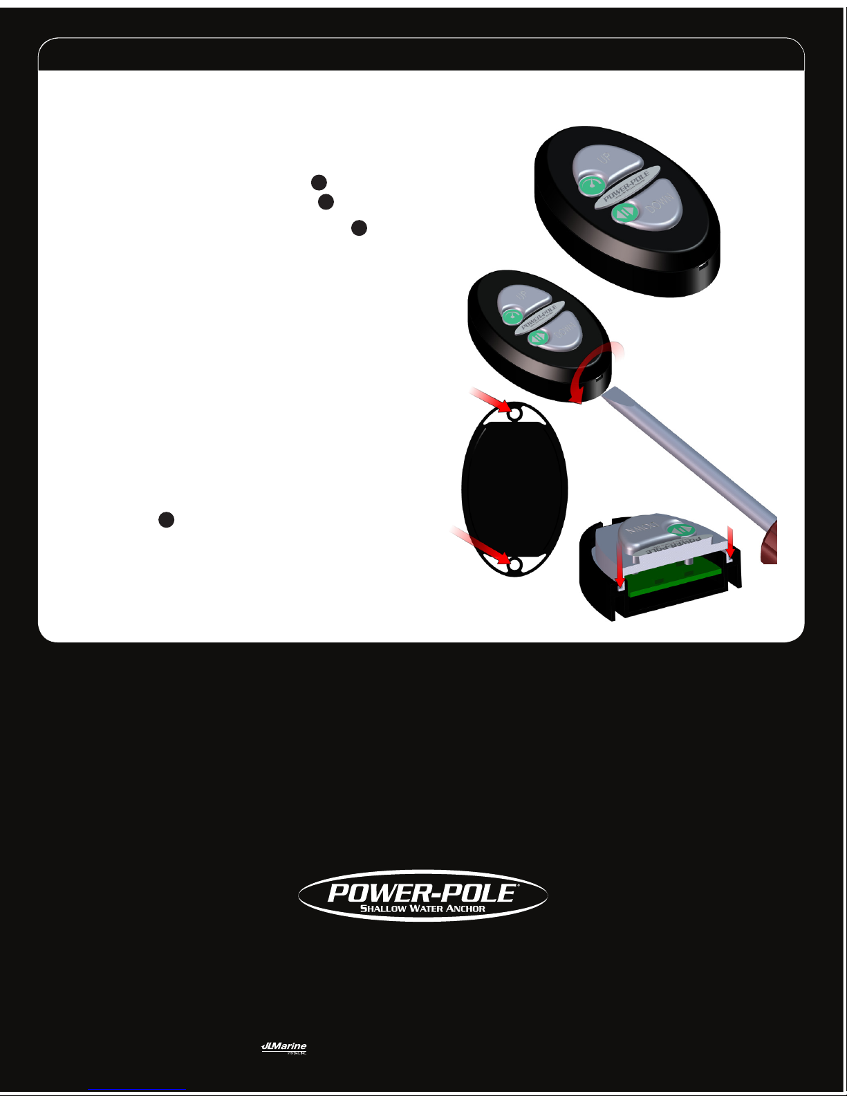
2. The dash switch must be installed with the slot in the
base facing downward, which can be accomplished
by using the supplied adhesive strip
N
or the (2)
included #6 x 1/2” pan head screws
G
.
3. If using the (2) #6 x 1/2” pan head screws
G
, use a
small slotted screwdriver to remove the dash switch
cover plate. (See Figure #12)
4. While holding the dash switch base in the desired
location, use a fine point marker to inscribe the
intended mounting screw locations.
WARNING: Before drilling pilot holes for the dash
switch mounting screws, inspect the area beneath
the mounting surface in order to ensure that the
drill bit will not cause any damage.
5. Using the 7/64” drill bit, carefully drill holes in the
previously inscribed location.
6. Fasten the dash switch base to the vessel using a #2
Phillips-head screwdriver and the (2) #6 x 1/2” pan
head screws
G
.
7. With the base installed, ensure that the rubber switch
membrane is seated properly prior to installing the
cover plate. (See Figure #13)
Need help? Contact our Technical Support Team at
813.689.9932 option 2
©2012 all rights reserved. Power-Pole Shallow Water Anchor U.S. Patent No. 6,041,730
Figure 12
Figure 13
 Loading...