

Power-Pole C-MONSTER 2.0 Instructions Manual
C-Monster 2.0 Controllers
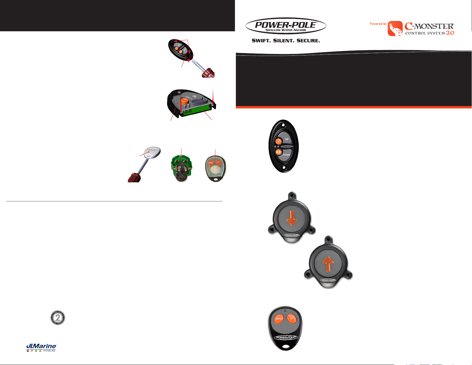
Battery Replacement (Dash Switch )
Screw Locations
IMPORTANT: Make sure battery replacement is done in a dry
location.
STEP 1: Remove the (2) screws using a Phillips-Head screwdriver.
STEP 2: Remove Dash Switch Cover using a Flat-Tip Screwdriver.
FIG. 1
STEP 3: Remove Switch Membrane and Circuit Board from the
Dash Switch Cover
Figure 1
base. FIG. 2
STEP 4: Remove battery from holder and replace with a CR2032 3v
Lithium Coin Battery.
STEP 5: Reassemble Dash Switch. Make sure Switch Membrane
is seated properly.
Battery Replacement (Key Fob)
Figure 2
Circuit BoardMembrane
IMPORTANT: Make sure battery replacement is done
in a dry location.
STEP 1: Remove Key Fob Cover using a Flat-Tip
Circuit Board
Membrane
screwdriver. FIG 1
STEP 2: Remove Switch Membrane and Circuit
Board from the base FIG 2
Key Fob
Cover
STEP 3: Remove battery from holder and replace
with a CR2032 3v Lithium Coin Battery.
STEP 4: Reassemble Key Fob. Make sure Switch
Figure 1
Figure 2
Figure 3
Membrane is seated properly.
General Statement (for all devices)
Warning: Changes or modifications to this device not expressly approved by JL Marine Systems, Inc. could void the user’s authority to operate the equipment.
FCC Specific Statement
NOTE: This equipment has been tested and found to comply with the limits for a Class B digital device, pursuant to Part 15 of the FCC Rules. These limits are
designed to provide reasonable protection against harmful interference in a residential installation. This equipment generate, uses, and can radiate radio
frequency energy and, if not installed and used in accordance with the instructions, may cause harmful interference to radio communications. However, there is
no guarantee that interference will not occur in a particular installation. If this equipment does cause harmful interference to radio or television reception, which
can be determined by turning the equipment off and on, he user is encouraged to try to correct the interference by one or more of the following measures:
• Reorient or relocate the receiving antenna.
• Increase the separation between the equipment and receiver
• Connect the equipment into an outlet on a circuit different from that to which the
• Consult the dealer or an experienced radio/TV technician for help
FCC Part 15.19 Warning Statement – (Required for all Part 15 devices) THIS DEVICE COMPLIES WITH PART 15 OF THE FCC RULES. OPERATION
IS SUBJECT TO THE FOLLOWING TWO CONDITIONS: (1) THIS DEVICE MAY NOT CAUSE HARMFUL INTERFERENCE, AND (2) THIS DEVICE MUST
ACCEPT ANY INTERFERENCE RECEIVED, INCLUDING INTERFERENCE THAT MAY CAUSE UNDESIRED OPERATION.
FCC/ISED RF Exposure
ENGLISH: This equipment complies with radiation exposure limits set forth for an uncontrolled environment. This equipment is in direct contact with the body of
the user under normal operating conditions. The transmitter must not be co-located or operating in conjuction with any other antenna or transmitter.
FRENCH: Cet équipment est conforme aux limites d’exposition aux radiations dans un environment non controle. Cet équipment est en contact direct avec le
corps de l’utilisateur dans des conditions de fonctionnement normales. Cet émetteur ne doit pas être co-localisées ou opérant en conjunction avec tout autre
antenne ou transmetteur.
ENGLISH: This device complies with Industry Canada license-exempt RSS standard(s). Operation is subject to the following two conditions: (1) this device may
not cause interference, and (2) this device must not accept any interference, including interference that may cause undesired operation of the device.
FRENCH: Le présent est conforme aux CNR d’Industrie Canada applicables aux appareils radio exempts de license. L’exploitation est autorisée aux deux
conditions suivantes: (1) l’appareil ne doit pas produire de brouillage, et (2) l’utilisateur de l’appareil doit accepter tout brouillage radioélectrique subi, même si
le brouillage est susceptible d’en compromettre le fonctionnement.
receiver is connected
To activate your warranty or find a Power-Pole Certified
2
Warranty Center, go to www.power-pole.com
Need help? Contact our Technical Support Team at 1 + 813.689.9932 Option 2
C-MONSTER 2.0 CONTROLLER
INSTRUCTIONS
WIRELESS DASH SWITCH
WIRELESS FOOT SWITCHES
REMOTE CONTROL KEY FOB
9010 Palm River Road, Tampa, Florida 33619
phone 813.689.9932 fax 813.689.8883 • power-pole.com
©2019 all rights reserved. Power-Pole Shallow Water Anchor U.S. Patent No. 6,041,730
C-Monster 2.0 Controllers
C-Monster 2.0 Controllers
PAIRING INSTRUCTIONS (All Controllers)
STEP 1: Press and hold the PROGRAM button on top of the unit
for 3 seconds (LED will turn GREEN/HPU will beep).
STEP 2: Press the UP or DOWN button on controller for one
second. When Paired, the GREEN LED will turn off
then flash steadily (HPU will also beep).
Pairing Dual Power-Poles: Repeat steps 1-2 to pair remote
to the other pump. Both pumps
can be programmed to a single
controller.
NOTE: The first time a remote is paired with a recently updated pump it may perform a firmware
update. Remote will blink for 1 minute. Do not interrupt power to pump or remote during
this process. Blinking will stop when update is finished.
Hydraulic Pump
Unit (HPU)
LED
UP but ton
PROGRAM button
DOWN bu tton
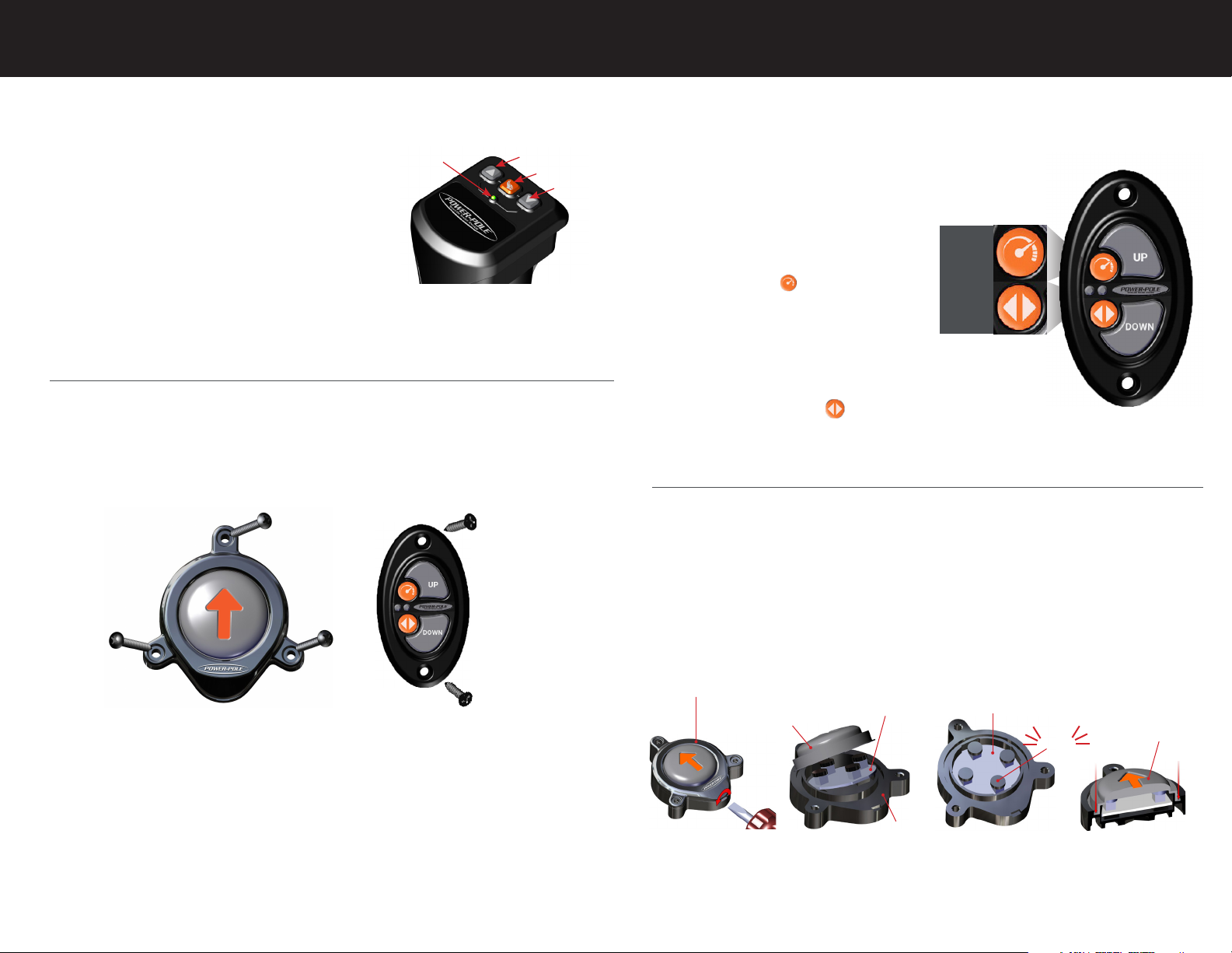
INSTALLATION INSTRUCTIONS (Dash and Foot Switches only)
STEP 1: Place switch flush in desired location and drill holes with a 1/8” drill bit/electric drill. Use
Switch holes as guide.
STEP 2: Fasten switches using the supplied screws and Phillips-Head Screwdriver.
Foot Switch Install Dash Switch Install
NOTES:
• Switches must be mounted on flat surface.
• Do not overtighten screws.
• Dash Switch may be installed with screws or adhesive strip.
OPERATING INSTRUCTIONS (All Controllers)
• Press and hold the UP/DOWN button on any controller to raise/lower the
Power-Pole Anchor.
Auto Mode:
• Double tap the UP/DOWN button on any
controller.
• Can be changed to single tap via the
C-Monster app.
Speed Control (Dash switch Only)
SPEED
BUTTON
Fittings
Facing
• Press the SPEED button on the switch to
toggle through the 3 speed settings (slow,
medium, fast).
DIRECTIONAL
BUTTON
• All Power-Pole Anchors are programmed
to 70% speed. Maximum speed can be
changed in the C-Monster App.
Dual Operation
• Press the DIRECTIONAL button on Dash
Switch to toggle through the three settings (port, starboard, or simultaneous control).
• Only Dash Switch can operate port/starboard anchors seperately.
Battery Replacement (Foot Switch)
IMPORTANT: Make sure battery replacement is done in a dry location.
STEP 1: Remove screws using a Phillips-Head screwdriver.
STEP 2: Remove Foot Switch Cover using a Flat-Tip Screwdriver. FIG. 1
STEP 3: Remove Switch Membrane and Circuit Board from the base FIG. 2
STEP 4: Remove battery from holder on back of circuit board and replace with a CR2032 3v Lithium
Coin Battery.
STEP 5: Reassemble Foot Switch. Make sure black caps click when pressed. If caps don’t click, rotate
board 1/4 turn and reinstall. FIG. 3 & 4
Foot Switch Cover
Switch Membrane
Circuit Board
Figure 2
Base
Circuit Board
Figure 3Figure 1
CLICK
Switch Membrane
Figure 4
Need help? Contact our Technical Support Team at 1 + 813.689.9932 Option 2
Need help? Contact our Technical Support Team at 1 + 813.689.9932 Option 2
 Loading...