

INSTALLATION
& OWNER GUIDE
Welcome to the world of Power-Pole®,
the original shallow water anchor.
INSTALLATION TOOLS
• 1/2”, 9/16”, 5/8” wrenches
• 1/2” & 9/16” sockets with ratchet
• drill
• 7/64”, 9/64”, 3/4”, 5/16” drill bits
• #2 Phillips-head bit or screwdriver
• Heat gun
• 4’ straight edge
• Marine grade sealant
• Fine point marker
• Tape measure
• Wire cutters
• Wire strippers
• Wire terminal crimpers
• Small funnel
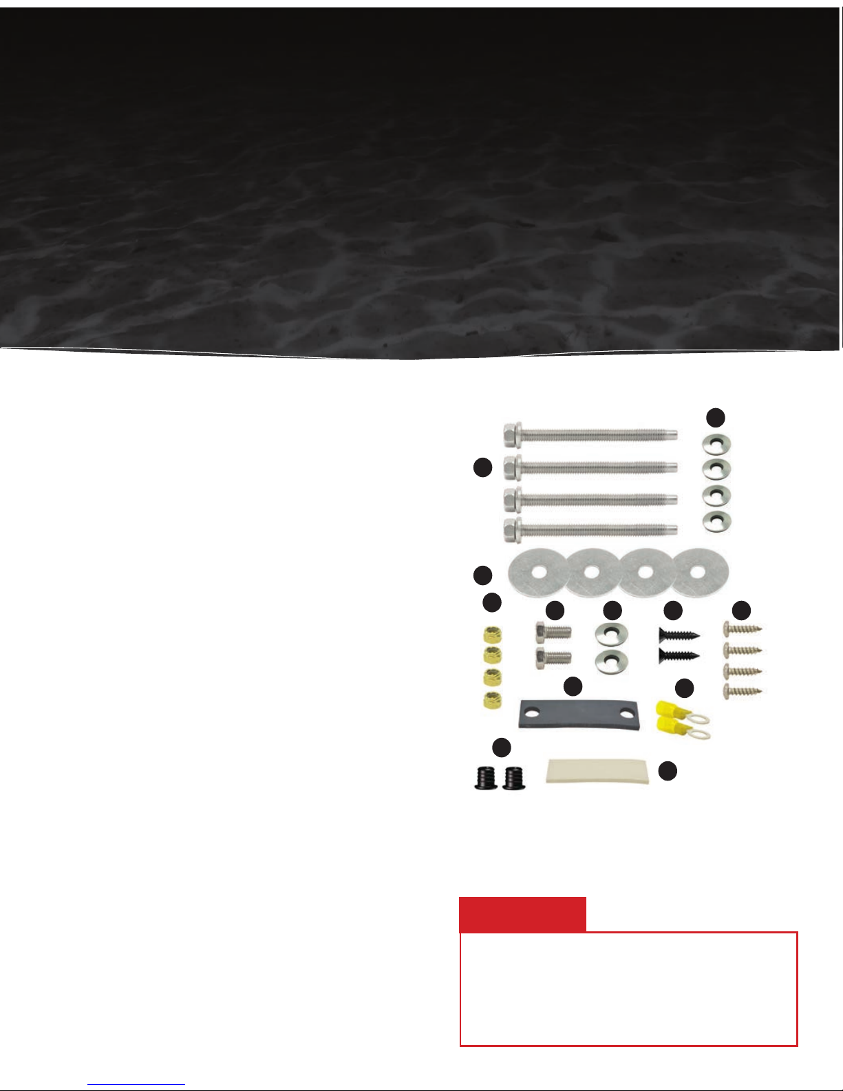
INSTALLATION HARDWARE
A
C
D
E F G H
I
J
K
L
B
A Qty(4) 5/16” x 3.5” all-thread transom mount bolts
B Qty(4) 5/16” neo-bond washers
C Qty(4) 5/16” fender washers
D Qty(4) 5/16” tall brass nuts
E Qty(2) 3/8” x 3/4” bolts
F Qty(2) 3/8” neo-bond washers
G Qty(2) #8 x 3/4” flat head screws (included with Dash Switch)
H Qty(4) #10 x 3/4” pan head screws
I Qty(1) rubber pump gasket
J Qty(2) ring terminal connectors
K Qty(2) thru-hull bushings (pre-installed on tubing)
L Qty(1) adhesive strip (included with Dash Switch)
Congratulations on your purchase of a Power-Pole® shallow water anchor featuring
C-Monster Control System. It has been designed, engineered, and manufactured to provide the
best possible performance and dependability. Please read all installation instructions carefully.
The information contained here describes the proper procedures for safely installing your
Power-Pole shallow water anchor. If you have questions, contact our Technical Support Team
at 1+ (813) 689-9932 option 2 or visit our website at www.power-pole.com.
INSTALLATION
Do not use the Power-Pole shallow water anchor
as your primary anchor. Never leave your boat
unattended while anchored solely with the PowerPole shallow water anchor.
CAUTION:
Adapter Plate Mounting
1. Follow the instructions included with your Power-Pole adapter plate. If you do not have an adapter plate,
please contact one of our authorized dealers or visit www.power-pole.com and click on “Accessories >
Find My Adapter Plate”. For technical support call 1+ (813) 689-9932 option 2.
Transom Mounting
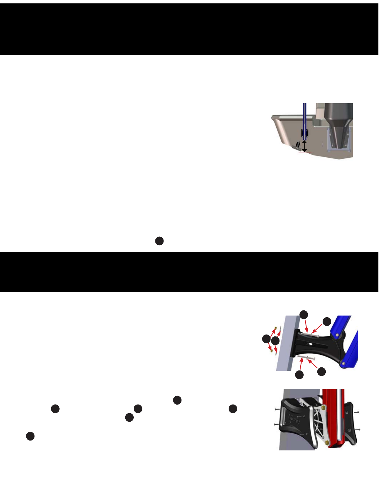
VERTICAL POSITIONING
1. Place a straight edge on the bottom of the hull directly below and centered from
the desired mounting location. The lowest point of the Power-Pole anchor must
be at least 4” above this straight edge or the vessel may experience adverse
handling effects. FIG. 1
NOTE:
If the vessel is equipped with trim tabs that measure 9” or less in length, the standard 4” minimum
mounting height will be sufficient. If the trim tabs are larger than 9”, the Power-Pole anchor will need to
be mounted higher up on the transom to prevent interference.
2. While holding the Power-Pole anchor in place, turn and tilt the motor as far as possible toward the unit.
With the motor turned toward the unit, manually move the anchor through its entire range of motion to
verify clearance.
3. Once clearance has been verified on the exterior portion of the vessel, check for adequate space on the inside
of the transom mounting area. Make sure that the bolts will not have any obstructions and that you will have
space to tighten the 5/16” tall brass nuts
D
.
4”
Figure 1
STEP1
Choose A Mounting Location
STEP2
Mounting The Anchor
1. Place the stern bracket against the transom, and mark the mounting holes with a
fine point marker.
NOTE:
If installing 8’ Blade shallow water anchor re-route hydraulic hose through
the stern bracket side outlets, with one hose out of each side. See Step 4
FIG. 6
2. Carefully drill pilot holes in each of the four marked locations with a 9/64”
drill bit. Then, drill out each of the four pilot holes with a 5/16” drill bit.
3. Apply a liberal amount of marine grade sealant between the stern bracket
and the hull, as well as around the 5/16” holes.
4. With a 1/2” wrench and 1/2” socket, fasten the stern bracket to the transom using
the (4) 5/16” x 3.5” all-thread transom mount bolts
A
, (4) 5/16” neo-bond
washers
B
(4) 5/16” fender washers C , and (4) 5/16” tall brass nuts D. The
rubber backed neo-bond washers
B
will protect the powder coated surface of
the stern bracket and they must not be over tightened. FIG. 2 Neo-bond washers
B
are not needed for 10’ Blade.
IMPORTANT:
Unit must be through bolted to transom.
NOTE: If installing 10’ Blade install the shroud ensuring not to over tighten the
screws. FIG. 3 (screws included with shroud.)
Figure 2
A
A
D
C
B
B
Figure 3
not needed for 10’ Blade
10’ Blade only

STEP3
Installing The Hydraulic Pump Unit (HPU)
Figure 4
H
1. Locate a dry compartment in the vessel with ample space
to accommodate the HPU. The footprint of the HPU is
approximately 6.5”x 7”.
NOTE:
Be sure to allow enough clearance surrounding the HPU
to install the (2) 3/8” x 3/4” bolts
E
through the mounting
bracket and into the HPU.
2. Remove the fill cap on the HPU and fill the reservoir to the “full”
line with the supplied quart of Green Marine® biodegradable
hydraulic fluid.
WARNING: Using anything other than an ISO 32 hydraulic fluid,
such as Green Marine, may cause damage to the
HPU.
3. Place the HPU bracket in the predetermined area of the vessel and mark the (4) mounting hole locations
with a fine point marker.
WARNING: Before drilling holes to mount the HPU mounting bracket, inspect the area beneath the
mounting surface to ensure that the drill bit will not cause any damage.
4. Drill a hole into each of the marked hole locations with a 9/64” drill bit.
5. Fasten the bracket to the vessel using a #2 Phillips-head screwdriver and the (4) #10 x 3/4” pan head
screws
H
. FIG. 4
6. Once the bracket is securely fastened, use a 9/16” wrench to attach the HPU to its bracket using the (2)
3/8” x 3/4” bolts
E
, (2) 3/8” neo-bond washers F, and (1) rubber pump gasket I. FIG. 5
7. Route the red wire to a 12 Volt positive source via a battery switch to prevent power draw when not in use.
8. Route the black wire to the 12 Volt negative common ground post.
9. Install the (2) ring terminal connectors
J
using wire strippers and wire terminal crimpers.
10. Heat the (2) ring terminal connectors J with a heat gun until their respective jackets shrink completely and
adhere to the wires.
WARNING: DO NOT CONNECT the red or black wire to the
battery at this time. These wires will be connected
once the hydraulic hose is installed.
Figure 5
I
E
F
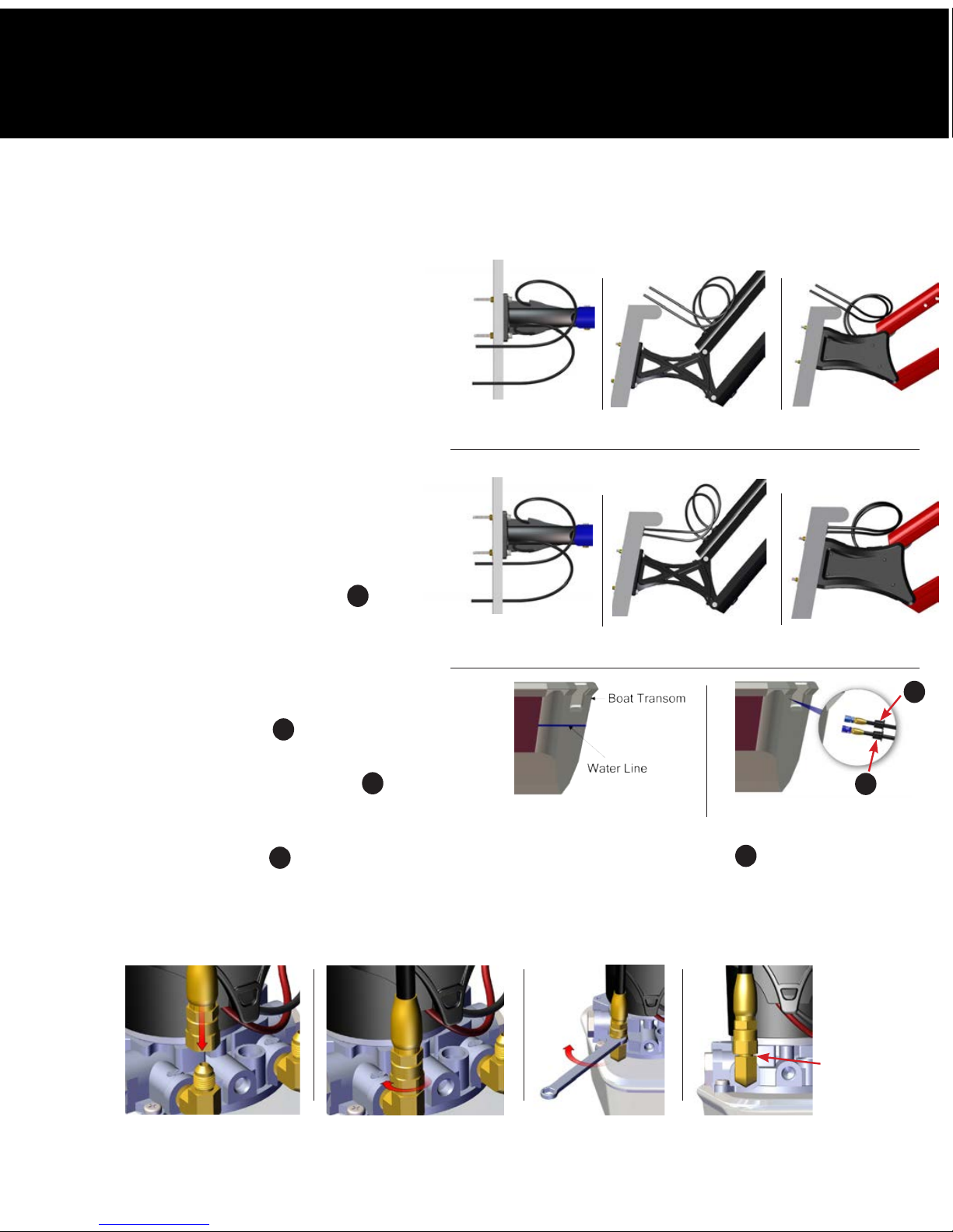
STEP4
Installing The Hydraulic Hose
1. The hydraulic hose may be routed either
over the transom or through the transom.
FI G. 6-11. If the hydraulic hose is not
being installed through the transom, route
the hose to the HPU and proceed to
Step 4 below.
IMPORTANT:
Be sure to allow an adequate
amount of slack in the
hydraulic hose between the
stern bracket and the point
that the hose enters the vessel.
This will provide for full up and
down operation.
2. Mark two 3/4” holes on the transom
above the water line for bushings
K
spaced 1-1/4” apart. Then, drill a pilot
hole in the middle of each marked hole
with a 5/16” drill bit. Next, drill pilot holes
out with a 3/4” drill bit, route hydraulic
hoses to HPU through transom holes and
install thru-hull bushings
K
. FIG. 12 & 13
IMPORTANT:
Put a small amount of marine
sealant around bushings K
before installing into the boat
transom.
NOTE:
Thru-hull bushings K can be removed from hydraulic hoses if thru-hull bushings K are not being used.
4. Remove the blue and black dust caps from the hydraulic fittings on the HPU.
5. Remove the “Insert Up Hose Here Tag” and finger tighten the hose labeled “Up” and then turn fitting a
quarter turn using a 5/8” wrench. F IG. 14 -17. Repeat this step for the DOWN hose.
Figure 6
BLADE 8’
Figure 9
BLADE 8’
Figure 8
BLADE 10’
Figure 11
BLADE 10’
Figure 7
PRO II & SPORTSMAN
Figure 10
PRO II & SPORTSMAN
Figure 12
Figure 13
WARNING: Keep debris out of the hydraulic hose. Do not remove blue plastic from the end of hydraulic hose
while routing throughout the boat. Debris in the hose will cause damage to the HPU.
K
K
Preferred
amount of
space
Figure 14
Figure 15 Figure 16 Figure 17
OVER THE TRANSOM
THROUGH THE TRANSOM

STEP5
Priming The HPU
1. Connect the red fuse holder ring terminal to the main
battery cut-off switch and the black ring terminal to
negative common ground post. The HPU will make a
charge audio ID tune and the LED indicator light will begin
flashing GREEN. FIG. 18
2. Manually place the Power-Pole anchor in the deployed
position.
3. Using the advanced dash switch remote control set to slow
speed, hold the down button until the RED LED on the
dash switch stops flashing and the pump stops running.
(Approximately 20 sec.) Repeat this process two more
times. See OPERATION section to change speed settings.
NOTE:
The HPU will have a high pitch whining sound while
priming until the air has dissipated from hydraulic fluid.
4. Check the fluid level in the reservoir and add if necessary.
5. Hold the up button until the RED LED on the dash switch
stops flashing and the pump stops running. (Approximately
20 sec.) Repeat this process two more times or until the Power-Pole anchor is fully retracted.
6. With the Power-Pole anchor in the retracted state, hold the down button until the RED LED on the dash
switch stops flashing and the pump stops running. Then hold the up button until the RED LED on the
dash switch stops flashing and the pump stops running. Repeat this step once.
7. Set the dash switch to medium speed.
8. Hold the down button until the RED LED on the dash switch stops flashing and the pump stops running.
Then hold the up button until the RED LED on the dash switch stops flashing and the pump stops
running. Repeat this step once.
9. With the Power-Pole anchor in the retracted state, manually apply a force to attempt to deploy the PowerPole anchor. If the Power-Pole anchor does not stay in the retracted state, repeat step 8 until it does.
10. Once on the water, navigate to an area that is deep enough to fully deploy your Power-Pole anchor
without it touching the bottom.
11. Using the dash switch set to medium speed, fully deploy and retract the Power-Pole anchor six times.
12. Your Power-Pole anchor should be completely primed at this point, but if you suspect it isn’t, repeat step
11 until it is or contact JL Marine System’s Inc. for Technical Support at 813-689-9932 Option 2.
Figure 18

NOTE: Each Power-Pole anchor is preprogrammed as a single unit. When
using only one anchor do not program as a port or starboard.
1. Determine which HPU controls the starboard side Power-Pole anchor
using the UP & DOWN buttons on both HPUs. FIG. 19
2. Locate the C-Monster PROGRAM button on the top of the starboard
HPU. Depress and hold it for 6 seconds until the LED flashes RED and
2 chimes are heard followed by a single beep. FIG. 20
3. Next, depress and release the UP button. The LED will flash RED 1 time
with a single beep indicating that the HPU has been assigned as the
starboard side unit. Press and release the PROGRAM button to save
and exit. The LED will flash RED 1 time with a single beep followed by
2 consecutive beeps.
4. On the port side HPU, repeat Step 2 to enter programming mode.
Next, depress and release the DOWN button on the HPU. The LED
will flash RED twice with 2 consecutive beeps indicating that the
programming has been completed successfully and the HPU has been
assigned as the port side unit. Press and release the PROGRAM button
to save and exit. The LED will flash RED 2 times with a double beep
followed by 2 consecutive beeps.
NOTE:
For additional menu settings please refer to the Operation Section.
DOWN button
UP button
LED
STEP6
Programming Dual Units
Figure 19
Figure 20
PROGRAM button
LED

NOTE: Each Power-Pole anchor comes paired to the included
Dash Switch and Key Fob remotes. When installing dual
anchors, you can program a single Dash Switch and/or
Key Fob remote to control both units as follows:
1. Determine which HPU is paired with the controller by
pressing the UP or DOWN button on the controller.
2. Press and hold the PROGR AM button on the other HPU
for 3 seconds until the LED turns GREEN and a single beep
is heard.
3. Press and release either the UP or DOWN button on the
controller until the unit responds. FIG. 21
IMPORTANT: The first time your remote is paired to a recently-
updated pump it may perform a firmware update. When this occurs the remote will blink for
approximately 1 minute. Please do not interrupt power to either the pump or remote during this
process. When the blinking has ceased your remote has finished updating and is ready to use.
NOTE: The pump will not update an unpaired remote.
1. Locate a suitable area with a flat surface to mount the
Dash Switch and mark the hole location with a fine point
marker.
2. Carefully drill the marked hole locations with a 7/64” drill
bit to fasten the switch using the (2) flat head screws
G
supplied (do not over tighten). Or you may choose to install
using the supplied adhesive strip
L
(not shown).
STEP7
STEP8
Pairing Dual Units To A Single Wireless Controller
Installing The Advanced Dash Switch
G
G
PROGRAM button
LED
Figure 21

HPU (Hydraulic Pump Unit) Using Top Side Control Functions
Figure 1
LED
DOWN button
PROGRAM button
UP button
OPERATION
Here you’ll find information on all of the functions, safe use, and proper maintenance of your shallow water
anchor. If you have questions, contact our Technical Support Team at 1 + (813) 689-9932 option 2 or visit our
website at www.power-pole.com.
LIGHT
INDICATION
Flashing GREEN Light
NORMAL: System has proper
voltage (11.9V – 16.4V).
Flashing ORANGE Light
LOW: System has low voltage
(10.8V – 11.8V).
Flashing RED Light
WARNING: System has low
voltage (10.7V or less).
NOTE: When voltage is below
6V or above 16.5V the unit
will not operate.
HPU INDICATOR LIGHT GUIDE
FUNCTION 1: Setting As A Single Port/Starboard Unit (Duals)
1. Depress and hold the C-Monster PROGRAM button for 6 seconds until LED flashes RED and 2 chimes are
heard followed by a single beep.
• To set as a single HPU: Press and hold both UP and DOWN buttons simultaneously.
• To set as starboard side HPU: Press and release the UP button.
• To set as port side HPU: Press and release the DOWN button.
Press both to set for Single Unit
Port (for duals)
Starboard
(for duals)
2. Once you have made all desired setting changes, press and release the PROGRAM button to save your
settings and exit program mode. You will hear a series of beeps and the LED will return to flashing GREEN.

Press UP for
higher speed
setting / higher
sensitivity
Highest tone level
(FASTEST)
Middle range tone level
(MEDIUM)
Lowest tone level
(SLOWEST)
Press DOWN for
lower speed /
lower sensitivity
10
1
Figure 1
3. Once you have made all desired setting changes, press and release the PROGRAM button to save your
settings and exit program made. You will hear a series of beeps and the LED will return to flashing GREEN.
FUNCTION 3: Up Sensitivity Adjustment
Controls the operation of the Auto Up feature. If the unit continues to run once retracted, increase the
sensitivity. If the unit stops running prematurely, decrease the sensitivity.
NOTE: Default settings are in the middle of the range. Tone increases with level (1-10). FIG. 1
1. Depress and hold the PROGRAM button for 6 seconds until LED flashes RED and 2 chimes are heard
followed by 3 beeps.
2. Press the UP for higher sensitivity setting and DOWN for lower sensitivity setting. FIG. 1
3. Once you have made all desired setting changes, press and release the PROGRAM button to save your
settings and exit program mode. You will hear a series of beeps and LED will return flashing GREEN.
FUNCTION 4: Down Sensitivity Adjustment
Controls the operation of the Auto DOWN feature. If the unit turns off prematurely during deployment,
decrease the sensitivity. If the unit continues to run once anchored, increase the sensitivity.
NOTE: Default settings are in the middle of the range. Tone increases with level (1-10). FIG. 1
1. Depress and hold the PROGRAM button for 6 seconds until LED flashes RED and 2 chimes are heard
followed by 4 beeps.
2. Press the UP for higher sensitivity setting and DOWN for lower sensitivity setting. FIG. 1
3.
Once you have made all desired setting changes, press and release the PROGRAM button to save your
settings and exit the program mode. You will hear a series of beeps and LED return flashing GREEN.
FUNCTION 2: Key-Fob Speed Adjustment
NOTE: Default settings are set to 70% of the highest speed level. Tone increases with level (1-10). FIG. 1
1. Depress and hold the C-Monster PROGRAM button for 6 seconds until LED flashes RED and 2 chimes
are heard followed by two beeps.
2. Press the UP button for higher speed setting and DOWN button for lower speed setting. FIG. 1

Advanced Dash Switch Remote Control
DEPLOYMENT OPTIONS
To raise or lower your Power-Pole anchor, press and hold either the
UP or DOWN button. The anchor will only continue to move as long
as you press the button.
AUTO MODE (DASH SWITCH)
Double tapping (pressing and releasing 2 times within 1 second)
either the UP or the DOWN button on the Dash Switch will cause the
anchor to retract or deploy automatically. The anchor will continue to
move in said direction until it either retracts completely (Auto Up)
or senses a solid bottom surface (Auto Down).
SPEED CONTROL
The Dash Switch has 3 speed settings (slow, medium, and fast). Pressing and releasing the Speed Control
button will toggle through the 3 settings. The LED lights will flash at a speed that corresponds to either a slow,
medium, or fast setting.
MULTIPLE ANCHORS
With multiple Power-Pole anchors, the Dash Switch can be used to toggle between independent or
simultaneous control of the anchors. Depressing and releasing the Directional Control button will toggle
through the multiple anchors. The LED lights will flash corresponding to either left, right, or both to indicate
the current control settings.
Standard Key Fob Remote Control
DEPLOYMENT OPTIONS
To raise or lower the Power-Pole anchor, press and hold either the UP or DOWN
button. The anchor will only continue to move as long as you press the button.
AUTO MODE (KEY FOB)
Double tapping (pressing and releasing 2 times within 1 second) either the
UP or DOWN button on the Key Fob will cause the anchor to retract or deploy
automatically. The anchor will continue to move in said direction until it either
retracts completely (Auto Up) or senses a solid button surface (Auto Down).
Speed Control
Directional Control
(Port, Starboard,
or Both selections)

C-MONSTER
Wireless Controller Battery
Replacement Instructions
Advanced Dash Switch
STEP 1
Remove the (2) #8 x 3/4”
flat head screws from
the top of dash switch.
STEP 2
Use a small slotted screwdriver to remove the dash
switch cover plate. FIG. 1
STEP 3
Remove the rubber switch membrane and the board
from the dash switch base.
STEP 4
Remove the battery from the holder on the back of
the board and replace with any CR2032 3V Lithium
Coin Battery.
STEP 5
Place the board and rubber switch membrane back into
the dash switch base and ensure that the rubber switch
membrane is seated properly prior to installing the cover
plate. FIG. 2
IMPORTANT:
Ensure the switch and the surrounding area is as dry as possible to avoid any moisture intrusion
before changing battery in controller.
Figure 1
Figure 2
Figure 2
Standard Key Fob Remote
STEP 1
Use a small slotted screwdriver to
remove the key fob cover. FIG. 1
STEP 2
Remove the rubber membrane
and the circuit board from
Key Fob base.
STEP 3
Remove the battery from the
holder on the front of circuit
board and replace with any
CR2032 3V Lithium Coin
Battery. FIG. 2
STEP 4
Place the circuit board and
rubber membrane back into
the Key Fob base and ensure
that the rubber membrane is
seated properly prior to installing
the cover. FIG. 3
Figure 1
Figure 3

C-MONSTER
Wireless Controller Battery
Replacement Instructions
continued
Standard Foot Switch
STEP 1
Remove the (3) screws with a #2 hillips head screwdriver.
STEP 2
Separate the foot switch cover from its base using a small slotted flat head
screwdriver. FIG. 1
STEP 3
Remove the rubber switch membrane and the circuit board from the foot
switch base. FIG. 2
STEP 4
Remove the battery from the holder on the back of the circuit board and
replace with any CR2032 3V Lithium Coin Battery.
STEP 5
Place the circuit board back into its base with circuit board level and small
black caps placed over each circuit board button. FIG. 3
NOTE:
Each small black cap when pressed should push down and
come up when released. If the black cap does not push down
remove black cap and rotate 1 quarter turn and reinstall.
STEP 6
Install rubber switch membrane back into the foot switch base and ensure
that the rubber switch membrane is seated properly prior to installing the
cover. FIG. 4
Figure 1
Figure 4
Switch Cover
Circuit Board
Figure 2
Circuit Board
Black Caps
Figure 3

DOWNLOAD
THE C-MONSTER APP @
MAINTENANCE and Storage
• Inspect all hydraulic lines for kinking or abrasion prior to use.
• Inspect all hydraulic fittings for leaks and proper tightness prior to each use.
CAUTION: If disconnecting the hydraulic lines, please read the following:
Hydraulic lines are always pressurized and disconnecting them will cause
a sudden high pressure release. This high pressure release may cause oil
leakage from the lines and/or fittings. When depressurizing the lines the
unit must be supported otherwise the anchor will fall to the fully deployed
position. This may result in damage to the unit as well as bodily harm.
• Inspect all electrical connections to ensure that they are secure and free of corrosion
every 3 months.
• Inspect all fasteners for proper tightness after every 100 cycles to ensure that
the Power-Pole anchor is in safe working condition.
NOTE: Tighten the 2 lower stern bracket lock nuts snug and all other lock nuts
flush with the end of bolt with no threads showing. FIG. 1 & 2
IMPORTANT: The stern bracket hinge bolts on the 10’ Blade model do not
require retightening.
• Ensure that the Green Marine® biodegradable hydraulic fluid level is within
the indicator marks on the reservoir at all times.
C-MONSTER
Smart Phone App
Figure 1
Figure 2
The C-Monster App is available for free from Google Play and the Apple App
Store. The C-Monster App allows you to do the following:
• Configure settings for custom operation. Take full control
of everything from deployment speed to independent or synchronized
control of multiple anchors. Not to mention Auto Up/Auto Down
and bottom sensing.
• Troubleshoot with AMP streaming instant diagnosis.
The information is sent directly to the Power-Pole Technical Support
Team so we can instantly see what’s happening and you can count
on little or no down time.
• Check signal strength of all your remotes with
RSSI evaluation.
This allows you to instantly see if your signal is weak or if any other devices
are disrupting your signal.
• Update software. You will recieve automatic prompts to update your
C-Monster software if a new version is available.
• Quick product registration. Now you can easily register your Power-Pole
anchors and accessories directly through the app.
• Theft recovery. Once you register your Power-Pole anchor with the C-Monster App,
if it’s ever stolen we can help law enforcement track and recover it.

• Thoroughly rinse all moving parts with fresh water after each use.
• Always ensure that your Power-Pole shallow water anchor is in the stowed position when traveling.
• Lubricate the bushings at both the stern bracket and knuckle hinge points with spray lithium grease
every 6 months. FIG. 3 & 4
NOTE: Lithium grease application does not apply to stern bracket on 10’ Blade.
PRECAUTIONS
• Prior to use, read this guide carefully. Become familiar with the controls and how to operate your
Power-Pole shallow water anchor properly.
• Do not allow children to operate or tamper with the Power-Pole shallow water anchor without
adult supervision.
• Do not modify the unit in any way.
• Use only genuine Power-Pole shallow water anchor accessories.
• Always disconnect the 12 Volt power source from the anchor before servicing.
• In the event of HPU failure, your Power-Pole anchor may be manually stowed by activating the pole
protector valve.
- Do so by applying enough upward force to lift the unit into its upright position.
- If the anchor is not within reach, you may drive the boat toward shallow water.
This will apply enough upward force to lift the unit within reach.
• Be sure to have your Power-Pole anchor in the stowed (fully upright) position while operating your vessel at
high speeds.
• Always maintain a safe distance between the anchor and your extremities. Avoid wearing loose clothing
within close proximity of the anchor; failure to do so may result in bodily injury.
• Do not use your Power-Pole shallow water anchor as a form of assistance for entering or exiting the vessel.
• Never leave your boat unattended with the Power-Pole anchor as the primary anchorage.
• During situations with high wind or rough seas, your Power-Pole anchor may release holding pressure in
order to protect your vessel’s transom.
• If any debris gets caught around your Power-Pole anchor, disconnect the 12 Volt power source prior
to removal.
Figure 3
Figure 4

FAQ
Frequently
Asked Questions
For Technical Support, please call 1+(813) 689-9932 option 2.
Q: Can my dual Power-Pole anchors be controlled independently?
A: Yes. The C-Monster Control system allows for the independent control of dual Power-Pole anchors. The included
Advanced C-Monster Dash Switch is capable of independent control, but the included Standard Key Fob is not.
Q: What maintenance is required with my Power-Pole shallow water anchor?
A: The lower pivot bolts on your Power-Pole anchor need to be checked every 100 cycles and tightened as needed.
Should you see any damaged bushings upon tightening, replace them immediately.
NOTE: This is not required for 10’ Blade models 2017 and later.
Q: How often should I change my hydraulic fluid?
A: While there is no recommended time interval for a hydraulic fluid flush, the fluid should be changed if there
is any visible debris in the reservoir. Additionally, if the fluid appears milky or white it should be changed
immediately; white fluid is a sign of water intrusion and the entire system should be checked for leaks.
Q: What type of hydraulic fluid should I use?
A: The HPU reservoir should be filled with Green Marine® biodegradable hydraulic fluid or an ISO 32 hydraulic
fluid. Green Marine is available through all authorized Power-Pole dealers.
Q: Are Power-Pole HPUs interchangeable?
A: No. All Power-Pole HPUs, while identical in appearance, are unique in regard to the pressures that they produce.
Certain anchor models require more pressure due to their size, while other anchors are set with higher pressures
in order to enhance performance. Aside from HPU pressures, all C-Monster units have an internal circuit board
containing firmware that is specific to each model.
Q: How will the Power-Pole affect my battery during operation?
A: The average life of a 12 Volt battery with 55 cold cranking amps is 1,200 cycles per charge.
Q: Will the C-Monster HPU drain my battery when it is not in in use?
A: No. Although the HPU should be powered off via a battery switch when stored, the amperage draw on your
vessel’s battery during hibernation mode is (6 mA) will be negligible. By default, the HPU will go into hibernation
mode after the Power-Pole anchor is idle for (6) hours. The LED on the HPU will no longer flash green when the
HPU goes into hibernation mode. When the HPU is awake it draws approximately (21mA) of current.
NOTE:
The mentioned hibernation feature is only available with the firmware 1.15 and later. A firmware update
may need to be performed using the C-Monster smart phone app or the C-Monster update utility found at
www.power-pole.com
Q: Do I need two HPUs in order to run dual Power-Poles?
A: Yes. We recommend the use of an independent pump system with each Power-Pole anchor for the following reasons:
• Dual Power-Pole anchors will not deploy at the same time and/or same rate using 1 pump.
• The relief valves will not function according to the intended design of the Power-Pole anchor and may
cause a mechanical failure when using only 1 pump system.
• Many features of our newer models will not be functional when a single pump is used.
• Damage is possible using 1 pump with 2 Power-Pole anchors and doing so will void all warranties.
Q: What should I do if my Power-Pole anchor is stuck in the deployed position?
A: If your Power-Pole anchor will not retract for any reason, simply drive toward shallow water and the pole
protector valve will allow the anchor to stow.
Q: How many wireless controllers can I program to my C-Monster System?
A: Up to ten (10) wireless controllers can be programmed to operate your single or dual Power-Pole anchors.

Q: How do I program a new wireless controller to my existing C-Monster system?
A: 1. Press and hold the PROGRAM button on top of the (HPU) hydraulic pump unit for 3 seconds until the LED
turns solid GREEN (HPU will also beep).
2. Press and hold either the UP or DOWN button on the wireless controller you are pairing until the
unit responds.
IMPORTANT: The first time your remote is paired to a recently-updated pump it may perform a firmware update.
When this occurs the remote will blink for approximately 1 minute. Please do not interrupt power
to either the pump or remote during this process. When the blinking has ceased your remote has
finished updating and is ready to use.
NOTE: The pump will not update an unpaired remote.
Q: How do I adjust the speed on my included wireless Key Fob remote?
A: The included Key Fob remote comes out of the box set to 70% of the highest speed level. This can be
adjusted by downloading the C-Monster App and connecting to the system via Bluetooth with your Android
powered smart phone or Apple iPhone. For manual adjustment, see Function 2 Key-Fob Speed Adjustment.
Q: How do I order a replacement spike?
A: Replacement spikes can only be ordered via phone. Simply call a member of our Technical Support Team
at 1+(813) 689-9932 option 2 for a free replacement. Before calling please be sure that you have your
serial number. Serial numbers are located on the bottom of the stern bracket on most models.
Q: Why does my Power-Pole anchor fall down over time?
A: This is caused by either an external or internal leak in the hydraulic system. First, check all hydraulic fittings
and hose for leaks. If no external leaks are found, please contact our Technical Support Team.
Q: What are JL Marine System’s hours of operation?
A: Business hours, including Technical Support hours, are listed at www.power-pole.com.

LIMITED
Warranty
To find a Certified Warranty Center, visit www.power-pole.com.
Five (5) Year Limited Warranty — Power-Pole Blade and PRO II Shallow Water Anchor
Three (3) Year Limited Warranty — Power-Pole Sportsman II Shallow Water Anchor
Conditions of this Warranty
A Power-Pole shallow water anchor manufactured by JL Marine systems Inc. is warranted against defects in material and
workmanship in the stern bracket, knuckle joint, hydraulic system, and electrical system, to the original end consumer from the
original purchase date, according to the following stipulations:
1. Power-Pole shallow water anchor warranties are activated when product is registered online at www.power-pole.com/register
or by using the C-Monster smart phone app or upon receipt by JL Marine Systems, Inc. of a completed warranty card, postdated
within (10) days of the original purchase date. Please retain your sales receipt as proof of purchase.
2. Install Genuine Power-Pole Merchandise ONLY. This warranty is void if any non authorized parts are used or installed.
3. This warranty is void if the Power-Pole shallow water anchor is used commercially, structurally altered, or subject to stress beyond
the physical limits of the manufactured material.
4. This warranty does not cover abrasion or abnormal abuse, nor does it cover the Power-Pole shallow water anchor for anything
other than its intended use.
5. JL Marine Systems, Inc. reserves the right to change products and designs without incurring any obligations to incorporate such
changes in already completed products, or those in the hands of dealers or consumers. Products repaired or replaced under this
warranty may or may not have these changes.
Shipping (Only applies to packages shipped within the Continental U.S.)
1. Parts which prove defective within (90) days from the date of purchase, JL Marine Systems, Inc. will pay for the replacement
product shipping and handling fees to and from the JL Marine Systems, Inc. manufacturing plant or some other place which JL
Marine Systems, Inc. might designate.
2. Parts which prove defective after (90) days but before (12) months from the date of purchase will also be repaired or replaced
free of charge, but there may be a shipping charge to JL Marine Systems, Inc. manufacturing plant or some other place which JL
Marine Systems, Inc. might designate.
3. Parts which prove defective after (12) months will also be repaired or replaced free of charge, but there may be a shipping and
handling charge to and from the JL Marine Systems, Inc. manufacturing plant or some other place which JL Marine Systems, Inc.
might designate.
Parts
1. A Stern bracket, Knuckle joint or U-channel, which proves defective before sixty (60) months for Blade & Pro II
and before thirty-six (36) months for Sportsman II models, will be repaired or replaced free of charge. In the case of
replacement, parts of same (or equivalent) model will be used.
2. The Hydraulic Pump Unit (HPU) which proves defective within (24) months from date of purchase will be repaired or
replaced free of charge. Pump damage due to incorrect hydraulic fluid, submersion or excessive exposure to water may
void this warranty.
3. The Powder Coated Finish on the Blade, Pro II and Sportsman II models is covered for a period of six (6) months not to
crack, chip or fade.
4. A Cylinder, hydraulic hose, Dash Switch or Key-Fob which proves defective within (24) months from date of purchase
will be repaired or replaced free of charge. In the case of replacement, parts of same (or equivalent) model will be used.
5. Spike unconditional lifetime guarantee.
6. This Warranty does not cover water damage in any way.
THE WARRANTY CONTAINED HEREIN IS THE EXCLUSIVE WARRANTY MADE BY JL Marine Systems, Inc. AND THERE ARE NO
OTHER WARRANTIES, EXPRESSED OR IMPLIED, INCLUDING A WARRANTY OF FITNESS FOR A PARTICULAR PURPOSE OR OF
MERCHANTABILITY MADE WITH RESPECT TO SUCH ANCHORS. JL Marine Systems, Inc., IS NOT LIABLE FOR ANY INJURY OR MISHAPS
SUSTAINED IN THE USE OF THIS PRODUCT. THE USER OF THIS PRODUCT ACKNOWLEDGES ASSUMED RISKS AND WAIVES ANY AND
ALL CLAIMS AGAINST JL Marine Systems, Inc. AND ANY OF IT’S AGENTS.
This warranty applies under conditions of normal use. The warranty does not cover: 1) defects caused by improper assembly or
disassembly; 2) defects occurring after purchase due to product modification, intentional damage, accident, misuse, abuse, negligence
or exposure to corrosive elements; 3) cosmetic damage and 4) labor or assembly costs. Except as provided herein, JL Marine Systems,
Inc. makes no express warranties, and any implied warranty, including without limitation any implied warranty of merchantability
or fitness for a particular purpose, is limited in its duration to the duration of the written limited warranty set forth herein. Except as
provided herein, JL Marine Systems, Inc. shall have no liability or responsibility to the purchaser or any other person or entity with
respect to any liability, loss or damage caused or alleged to be caused directly or indirectly by use of the product, including, but not
limited to, any incidental or consequential damages. Some states do not allow limitation on how long an implied warranty lasts or
the exclusion of limitation of incidental or consequential damages, so the above limitation and exclusion may not apply to you. This
warranty gives you specific legal rights. You may also have other rights which vary from state to state.

©2017 all rights reserved. Power-Pole Shallow Water Anchor U.S. Patent No. 6,041,730
General Statement
Warning: Changes or modifications to this device not expressly approved by JL Marine Systems, Inc. could void the user’s authority to
operate the equipment.
FCC Specific Statement
NOTE: This equipment has been tested and found to comply with the limits for a Class B digital device, pursuant to Part 15 of the
FCC Rules. These limits are designed to provide reasonable protection against harmful interference in a residential installation. This
equipment generate, uses, and can radiate radio frequency energy and, if not installed and used in accordance with the instructions,
may cause harmful interference to radio communications. However, there is no guarantee that interference will not occur in a particular
installation. If this equipment does cause harmful interference to radio or television receptio, which can be dteremined by turning the
equipment off and on, he user is encouraged to try to correct the interferecne by one or more of the following measures:
• Reorient or relocate the receiving antenna.
• Increase the separation between the equipment and receiver
• Connect the equipment into an outlet on a circuit different from that to which the receiver is connected
• Consult the dealer or an experienced radio/TV technician for help
RF Exposure
ENGLISH: This equipment complies with radiation exposure limits set forth for an uncontrolled environment. This equipment is in direct
contact with the body of the user under normal operating conditions. The transmitter must not be co-located or operating in conjuction
with any other antenna or transmitter.
FRENCH: Cet équipment est conforme aux limites d’exposition aux radiations dans un environment non controle. Cet équipment est en
contact direct avec le corps de l’utilisateur dans des conditions de fonctionnement normales. Cet émetteur ne doit pas être co-localisées
ou opérant en conjunction avec tout autre antenne ou transmetteur.
ENGLISH: This device complies with Industry Canada license-exempt RSS standard(s). Operation is subject to the following two
conditions: (1) this device may not cause interference, and (2) this device must not accept any interference, including interference that
may cause undesired operation of the device.
FRENCH: Le présent est conforme aux CNR d’Industrie Canada applicables aux appareils radio exempts de license. L’exploitation est
autorisée aux deux conditions suivantes: (1) l’appareil ne doit pas produire de brouillage, et (2) l’utilisateur de l’appareil doit accepter
tout brouillage radioélectrique subi, même si le brouillage est susceptible d’en compromettre le fonctionnement.
Man-owner-internat-122016
9010 Palm River Road, Tampa, Florida 33619
Phone 1+(813) 689-9932 Fax 1+(813) 689-8883
www.power-pole.com
CAUTION:
Do not use the Power-Pole shallow water anchor as your primary anchorge. Never leave
your boat unattended while anchored solely with the Power-Pole shallow water anchor.
 Loading...