

Page 1

POWXQ8125 EN
1 SYMBOLS ........................................................................................ 2
2 GENERAL POWER TOOL SAFETY WARNINGS .......................... 2
2.1 Work area ................................................................................................................ 2
2.2 Electrical safety ....................................................................................................... 2
2.3 Personal safety ....................................................................................................... 3
2.4 Power tool use and care ......................................................................................... 3
2.5 Service ..................................................................................................................... 4
3 PRECAUTIONS ................................................................................ 4
3.1 Things to do ............................................................................................................ 4
3.2 Things not to do ...................................................................................................... 4
3.3 Things you should know ........................................................................................ 5
4 START-UP AND USE ...................................................................... 5
5 TECHNICAL DATA .......................................................................... 6
6 MAINTENANCE ............................................................................... 6
7 MAINTENANCE SCHEDULE .......................................................... 7
8 POSSIBLE FAULTS AND RELATED PERMITTED REMEDIES .... 7
9 WARRANTY ..................................................................................... 8
10 ENVIRONMENT ............................................................................... 9
11 DECLARATION OF CONFORMITY .............................................. 10
Copyright © 2010 VARO P a g e | 1 www.varo.com
Page 2
POWXQ8125 EN
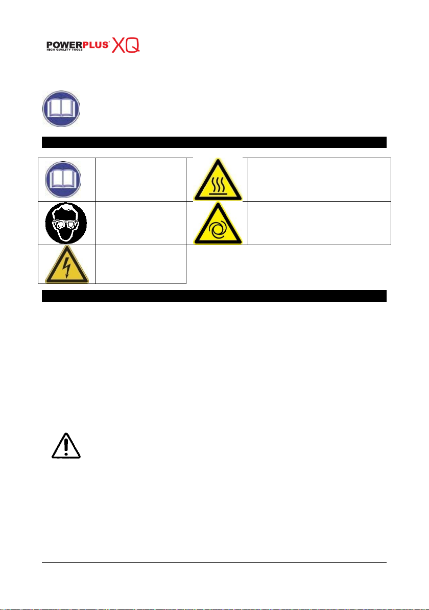
Before use, read the
handbook carefully
Warning, hot surfaces
Obligatory eye
protection
Danger - automatic control (closed
loop)
Dangerous voltage
COMPRESSOR 3HP – 50L
POWXQ8125
WARNING! Read this manual and general safety instructions carefully
before using the appliance, for your own safety. Your power tool should
only be passed on together with these instructions.
1 SYMBOLS
In this manual and/or on the machine the following symbols are used:
2 GENERAL POWER TOOL SAFETY WARNINGS
Read all safety warnings and all instructions. Failure to follow all warnings and instructions
may result in electric shock, fire and/or serious injury. Save all warnings and instructions for
future reference. The term "power tool" in the warnings refers to your mains operated (corded)
power tool or battery operated (cordless) power tool.
2.1 Work area
Keep work area clean and well lit. Cluttered and dark areas invite accidents.
Do not operate power tools in explosive atmospheres, such as in the presence of
flammable liquids, gases or dust. Power tools create sparks which may ignite the dust or
fumes.
Keep children and bystanders away while operating a power tool. Distractions can cause
you to lose control.
2.2 Electrical safety
Always check that the power supply corresponds to the voltage on the
rating plate.
Power tool plugs must match the outlet. Never modify the plug in any way. Do not use
any adapter plugs with earthed (grounded) power tools. Unmodified plugs and matching
outlets will reduce risk of electric shock.
Avoid body contact with earthed or grounded surfaces such as pipes, radiators, ranges
and refrigerators. There is an increased risk of electric shock if your body is earthed or
grounded.
Do not expose power tools to rain or wet conditions. Water entering a power tool will
increase the risk of electric shock.
Copyright © 2010 VARO P a g e | 2 www.varo.com
Page 3

Do not abuse the cord. Never use the cord for carrying, pulling or unplugging the power
POWXQ8125 EN
tool. Keep cord away from heat, oil, sharp edges or moving parts. Damaged or entangled
cords increase the risk of electric shock.
When operating a power tool outdoors, use an extension cord suitable for outdoor use.
Use of a cord suitable for outdoor use reduces the risk of electric shock.
If operating a power tool in a damp location is unavoidable, use a residual current device
(RCD) protected supply. Use of an RCD reduces the risk of electric shock.
2.3 Personal safety
Stay alert, watch what you are doing and use common sense when operating a power
tool. Do not use a power tool while you are tired or under the influence of drugs, alcohol or
medication. A moment of inattention while operating power tools may result in serious
personal injury.
Use safety equipment. Always wear eye protection. Safety equipment such as dust mask,
non-skid safety shoes, hard hat, or hearing protection used whenever conditions require
will reduce personal injuries.
Avoid accidental starting. Ensure the switch is in the off position before plugging in.
Carrying power tools with your finger on the switch or plugging in power tools that have
the switch on invites accidents.
Remove any adjusting key or wrench before turning the power tool on. A wrench or a key
left attached to a rotating part of the power tool may result in personal injury.
Do not overreach. Keep proper footing and balance at all times. This enables better
control of the power tool in unexpected situations.
Dress properly. Do not wear loose clothing or jewellery. Keep your hair, clothing and
gloves away from moving parts. Loose clothes, jewellery or long hair can be caught in
moving parts.
If devices are provided for the connection of dust extraction and collection facilities,
ensure these are connected and properly used. Use of these devices can reduce dust
related hazards.
2.4 Power tool use and care
Do not force the power tool. Use the correct power tool for your application. The correct
power tool will do the job better and safer at the rate for which it was designed.
Do not use the power tool if the switch does not turn it on and off. Any power tool that
cannot be controlled with the switch is dangerous and must be repaired.
Disconnect the plug from the power source before making any adjustments, changing
accessories, or storing power tools. Such preventive safety measures reduce the risk of
starting the power tool accidentally.
Store idle power tools out of the reach of children and do not allow persons unfamiliar with
the power tool or these instructions to operate the power tool. Power tools are dangerous
in the hands of untrained users.
Maintain power tools. Check for misalignment or sticking of moving parts, breakage of
parts and any other condition that may affect the power tool’s operation. If damaged, have
the power tool repaired before use. Many accidents are caused by poorly maintained
power tools.
Keep cutting tools sharp and clean. Properly maintained cutting tools with sharp cutting
edges are less likely to stick and are easier to control.
Use the power tool, accessories and tool bits etc., in accordance with these instructions
and in the manner intended for the particular type of power tool, taking into account the
working conditions and the work to be performed. Use of the power tool for operations
different from intended could lead to a hazardous situation.
Copyright © 2010 VARO P a g e | 3 www.varo.com
Page 4

POWXQ8125 EN
2.5 Service
Have your power tool serviced by a qualified repair person using only identical
replacement parts. This will ensure that the safety of the power tool is maintained.
3 PRECAUTIONS
3.1 Things to do
The compressor must be used in a suitable environment (well ventilated with an ambient
temperature of between +5°C and +40°C) and never in places affected by dust, acids,
vapors, explosive or flammable gases.
Always maintain a safety distance of at least 4 meters between the compressor and the
work area.
Any coloring of the belt guards of the compressor during painting operations indicates that
the distance is too short.
Insert the plug of the electric cable in a socket of suitable shape, voltage and frequency
complying with current regulations.
For three-phase versions have the plug fitted by a qualified electrician according to local
regulations. The first time you start the compressor, check that the direction of rotation is
correct and matches that indicated by the arrow on the conveyor (Fig. 1, the air must be
conveyed towards the head of the compressor).
Use extension cables with a maximum length of 5 meters and of suitable cross-section.
The use of extension cables of different length and also of adapters and multiple sockets
should be avoided.
Always use the switch of the pressure switch to switch off the compressor
Always use the handle to move the compressor.
When operating, the compressor must be placed on a stable, horizontal surface to
guarantee correct lubrication.
Position the compressor at least 50 cm from the wall to permit optimal circulation of fresh
air and to guarantee correct cooling.
3.2 Things not to do
Never direct the jet of air towards persons, animals or your body. (Always wear safety
goggles to protect your eyes against flying objects that may be lifted by the jet of air).
Never direct the jet of liquids sprayed by tools connected to the compressor towards the
compressor.
Never use the appliance with bare feet or wet hands or feet.
Never pull the power cable to disconnect the plug from the socket or to move the
compressor.
Never leave the appliance exposed to adverse weather conditions.
Never transport the compressor with the receiver under pressure.
Do not weld or machine the receiver. In the case of faults or rusting, replace the entire
receiver.
Never allow inexpert persons to use the compressor. Keep children and animals at a
distance from the work area.
Do not position flammable or nylon/fabric objects closed to and/or on the compressor.
Never clean the compressor with flammable liquids or solvents. Check that you have
unplugged the compressor and clean with a damp cloth only.
The compressor must be used only for air compression. Do not use the compressor for
any other type of gas.
The compressed air produced by the compressor cannot not be used for pharmaceutical,
food or medical purposes except after particular treatments and cannot be used to fill the
air bottles of scuba divers.
Never use the compressor without guards (belt guard) and never touch moving parts.
Copyright © 2010 VARO P a g e | 4 www.varo.com
Page 5

3.3 Things you should know
To avoid overheating of the electric motor, this compressor is designed for intermittent
operation as indicated on the dataplate (for example, S3-50 means 5 minutes ON and 5
minutes OFF). In the case of overheating, the thermal cutout of the motor trips,
automatically cutting off the power when the temperature is too high due to excess current
takeoff.
To facilitate machine restart, it is important not only to carry out the operations indicated
but also to set the button of the pressure switch, returning this to the OFF position and
then ON again (figures 1a-1b).
On single-phase versions, press the reset button on the terminal box of the motor (fig. 2).
On 3-phase versions, operate manually on the button of the pressure switch, returning this
to the ON position, or press the button of the thermal cutout inside the box of the electric
panel (figures 3a-3b-3c).
The single-phase versions are fitted with a pressure switch equipped with a delayed
closing air vent valve (or with a valve located on the check valve) that facilitates motor
start-up; therefore a few-second jet of air from this, with the reservoir empty, is to be
considered normal.
To guarantee machine safety, all the compressors are fitted with a safety valve that is
activated in the case of failure of the pressure switch (fig. 4).
When connecting an air-powered tool to a hose of compressed air supplied by the
compressor, interruption of the flow of air from the hose is compulsory.
Use of the compressed air for the various purposes envisaged (inflation, air-powered
tools, painting, washing with water-based detergents only, etc.) requires knowledge of and
compliance with the rules established for each individual use.
4 START-UP AND USE
Fit the wheels and foot (or the caster wheel for models that are fitted with this) according
to the instructions provided in the packaging. For versions with fixed feet, assemble the
front bracket kit or the vibration-dampers if furnished. Check that the rating data match the
effective characteristics of the system (voltage and power).
Check for correspondence between the compressor plate data with the actual
specifications of the electrical system. A variation of ± 10% with respect of the rated value
is allowed.
Insert the power plug in a suitable socket checking that the button of the pressure switch
located on the compressor is in the “O” (OFF) position (figures 5a-5b-5c-5d).
For the 3-phase versions, connect the plug to a panel protected by suitable fuses.
For the versions fitted with electric panel (“Tandem” control units or delta/star starters)
have installation and connections (to the motor, to the pressure switch and to the
electrovalve if any) carried out by qualified personnel.
Check the oil level using the sight glass and if necessary unscrew the vent plug and top
up. (figures 6a-6b).
At this point, the compressor is ready for use.
Operating on the switch of the pressure switch (or the selector for versions with electric
panel, (figures 5a-5b-5c-5d), the compressor starts, pumping air in the reservoir through
the delivery hose.
On reaching maximum operating pressure (factory-set during testing), the compressor
stops, venting the excess air present in the head and in the delivery hose through a valve
located under the pressure switch (in delta/ star versions, through an electrovalve that is
activated when the motor stops).
The absence of pressure in the head facilitates subsequent restart. When air is used, the
compressor restarts automatically when the lower calibration value is reached (approx. 2
bar between upper and lower). The pressure inside the reservoir can be checked on the
gauge provided (fig. 4).
POWXQ8125 EN
Copyright © 2010 VARO P a g e | 5 www.varo.com
Page 6

The compressor continues to operate automatically with this work cycle until the position
Type
POWXQ8125
Rated power
3hp
Current take-off
5A
Power supply voltage
230 V/50 Hz
Air intake
270l/min
Maximum pressure
10bar
Weight
+/- 48kg
Isolation class
B
Tank capacity
50l
TABLE 1 – TIGHTENING OF HEAD TENSION RODS
Nm
Min torque
Nm
Max torque
Screw M6 9 11
Screw M8
22
27
Screw M10
45
55
Screw M12
76
93
Screw M14
121
148
of the switch of the pressure switch (or of the selector of the electric panel) figures 5a-5b5c-5d) is modified. To use the compressor again, wait at least 10 seconds after this has
been switched off before restarting.
In the versions with electric panel, the pressure switch must always be aligned with the I
(ON) position.
In tandem versions, the control unit provided permits use of only one of the two
compressor groups (if necessary alternatively) or of both at the same time according to
requirements. In this second case, start-up will be differentiated slightly to avoid
excessively high current take-off at start-up (timed starting).
Only the wheel-mounted compressors are fitted with a pressure reducer (in the versions
with fixed feet, it is usually installed on the use line). Air pressure can be regulated in order
to optimize use of air-powered tools operating on the knob with the valve open (pulling it
up and turning it in a clockwise direction to increase pressure and counterclockwise to
reduce this) (fig. 7). Once you have set the value required, push the knob down to lock it.
The value set can be checked on the gauge (for versions equipped with this, fig. 8).
Please check that the air consumption and the maximum working pressure of the
pneumatic tool to be used are compatible with the pressure set on the pressure regulator
and with the amount of air supplied by the compressor.
When you have finished working, stop the machine, pull out the plug and empty the
reservoir.
5 TECHNICAL DATA
POWXQ8125 EN
6 MAINTENANCE
The service life of the machine depends on maintenance quality.
PRIOR TO ANY OPERATION SET THE PRESSURE SWITCH TO THE OFF POSITION,
PULL OUT THE PLUG AND COMPLETELY DRAIN THE RESERVOIR.
Check that all screws (in particular those of the head of the unit) are tightly drawn up (fig.
9). The check must be carried out prior to the first compressor starting.
Clean the suction filter according to the type of environment and in any case at least every
100 hours. If necessary, replace the filter (a clogged filter impairs efficiency while an
inefficient filter causes harsher wear on the compressor (figures 10a - 10b).
Copyright © 2010 VARO P a g e | 6 www.varo.com
Page 7

Change the oil after the first 100 hours of operation and subsequently every 300 hours.
Fault
Cause
Remedy
Air leak from the valve of
the pressure switch.
Check valve does not
perform its function
correctly due to wear
or dirt on the seal.
Unscrew the hex-shaped head of
the check valve, clean the housing
and the special rubber disk (replace
if worn). Re-assembler and tighten
carefully (figures 14a-14b).
Condensate drainage
cock open.
Close the Condensate drainage
cock.
Rilsan hose not
inserted correctly in
pressure switch.
Insert the Rilsan hose correctly
inside the pressure switch (fig. 15).
Reduction of efficiency,
frequent start-up. Low
pressure values.
Excessively high
consumption
Decrease the demand of
compressed air
Leaks from joints
and/or pipes.
Change gaskets.
Clogging of the suction
filter.
Clean/replace the suction filter
(figures 10a-10b).
Slipping of the belt.
Check belt tension (fig. 13).
The motor and/or the
compressor overheat
irregularly.
Insufficient ventilation.
Improve ambient conditions
Closing of air ducts.
Check and if necessary clean the air
filter.
Insufficient lubrication.
Top up or change oil (figures 16a16b-16c).
Check the oil level periodically.
Use API CC/SC SAE 40. (For cold climates, API CC/SC SAE 20 is recommended). Never
mix different grade oils. If the oil changes color (whitish = presence of water; dark =
overheated), it is good practice to replace the oil immediately.
After topping up, tighten the plug (fig. 11) making sure that there are no leaks during use.
Once a week, check the oil level to assure lubrication in time (fig. 6a).
Periodically (or after completing work if for more than an hour), drain the condensate that
forms inside the reservoir due to the humidity in the air (fig. 12) in order to protect the
reservoir from rust and so as not to restrict its capacity.
Periodically, check the tension of the belts which must have a flexion (f) of around 1 cm
(fig. 13).
7 MAINTENANCE SCHEDULE
POWXQ8125 EN
Cleaning of intake filter and/ or substitution of filtering element: every 100 hours
Change of oil: After the first 100 hours + every 300 hours
Tightening of head tension rods: The check must be carried out prior to the first
compressor starting
Draining tank condensate: Periodically and at the end of work
Checking the tension of the belts: Periodically
Spent oil and condensate MUST BE DISPOSED OF in compliance with protection of the
environment and current legislation.
The compressor must be disposed in conformity with the methods provided for by local
regulations
8 POSSIBLE FAULTS AND RELATED PERMITTED REMEDIES
Copyright © 2010 VARO P a g e | 7 www.varo.com
Page 8

POWXQ8125 EN
Fault
Cause
Remedy
After an attempt to start the
compressor, it stops due to
tripping of the thermal
cutout caused by forcing of
the motor.
Start-up with head of
the compressor
charged.
Release the compressor head by
using the pressure switch push
button.
Low temperature
Improve ambient conditions
Voltage too low.
Check that the mains voltage
matches that of the dataplate.
Eliminate any extensions.
After an attempt to start the
compressor, it stops due to
tripping of the thermal
cutout caused by forcing of
the motor.
Incorrect or insufficient
lubrication.
Check level, top up and if necessary
change the oil.
Inefficient electrovalve.
Call the Service Center
During operation, the
compressor stops for no
apparent reason.
Tripping of the thermal
cutout of the motor.
Check level oil.
Single-stage, mono-phase versions:
operate on the button of the
pressure switch returning this to the
OFF position (fig. 1a). Reset the
thermal cutout (fig. 2) and restart
(figures 1b). If the fault persists, call
the Service Center
Versions with delta-star starter:
operate on the button of the thermal
cutout located inside the box of the
electric panel (fig. 3c) and restart
(fig. 5d). If the fault persists, call the
Service Center.
Other versions: Operate on the
button of the pressure switch
returning this to the OFF position
and then to ON again (fig. 1a-1b). If
the fault persists, call the Service
Center.
Electric fault.
Call the Service Center.
When operating, the
compressor vibrates and the
motor emits an irregular
buzzing sound. If it stops, it
does not restart although
the sound of the motor is
present.
Single-phase motors:
faulty capacitor.
Have the capacitor replaced.
3-phase motors: One
of the phases of the 3phase power supply is
missing due probably
to blowing of a fuse.
Check the fuses inside the electric
panel or the electric box and if
necessary replace those that have
been damaged (fig. 17).
Irregular presence of oil in
the network.
Too much oil inside the
unit.
Check oil level.
Wear on segments.
Call the Service Center.
Leaking of condensate from
the vent cock.
Presence of dirt/grit
inside the cock.
Clean the cock.
9 WARRANTY
This product is warranted for a 5-year period effective from the date of purchase by the
first user.
Copyright © 2010 VARO P a g e | 8 www.varo.com
Page 9

This warranty covers all material or production flaws. It does not include defective parts
POWXQ8125 EN
subject to normal wear & tear such as bearings, brushes, cables, and plugs, or
accessories such as drills, drill bits, saw blades, etc. ; damage or defects resulting from
maltreatment, accidents or alterations; nor the cost of transportation.
At the same time, no claim can be made on the warranty if the damage of the device is the
result of negligent maintenance or overload.
Definitely excluded from the warranty is damage resulting from fluid permeation, excessive
dust penetration, intentional damage (on purpose or by gross carelessness), inappropriate
usage (use for purposes for which the device is not suitable), incompetent usage (e.g. not
following the instructions given in the manual), inexpert assembly, lightning strike,
erroneus net voltage. This list is not exhaustive.
Acceptance of claims under warranty can never lead to the prolongation of the warranty
period nor commencement of a new warranty period in case of a device replacement.
Devices or parts which are replaced under the warranty therefore remain the property of
Varo NV.
We reserve the right to reject a claim whenever the purchase cannot be verified or when it
is clear that the product has not been properly maintained. (Clean ventilation slots, carbon
brushes serviced regularly, etc.).
Your purchase receipt must be kept as proof of date of purchase.
Your appliance must be returned undismantled to your dealer in an acceptably clean state,
(in its original blow-moulded case if applicable to the unit), accompanied by proof of
purchase.
10 ENVIRONMENT
Should your appliance need replacement after extended use, do not discard it
with the household rubbish but dispose of it in an environmentally safe way.
Waste produced by electrical machine items should not be handled like normal
household rubbish. Please recycle where recycle facilities exist. Check with your
Local Authority or retailer for recycling advice.
Copyright © 2010 VARO P a g e | 9 www.varo.com
Page 10

POWXQ8125 EN
11 DECLARATION OF CONFORMITY
VARO N.V. - Joseph Van Instraat 9 - BE2500 Lier - BELGIUM, declares that,
product: Compressor
trade mark: POWERplus
model: POWXQ8125
is in conformity with the essential requirements and other relevant provisions of the applicable
European Directives, based on the application of European harmonized standards. Any
unauthorized modification of the apparatus voids this declaration.
European Directives (including, if applicable, their amending directives):
2006/95/EC The Low Voltage Directive
2004/108/EC The Electromagnetic Compatibility Directive
2006/42/EC The Machinery Directive
2000/14/EC The Outdoor Noise Directive
IT
87/404/EEC The Simple Pressure Vessel Directive
European harmonized standards, and their amendments:
EN1012-1 : 1996
EN60204-1 : 2006
EN55014-1 : 2006
EN55014-2 : 1997
EN61000-3-2 : 2006
EN61000-3-3 : 1995
The undersigned acts on behalf and under the power of attorney of the company
management,
LwA = 96dB(A)
Testing Authority DNV
Testing Authority CPM
IT
Philippe Vankerkhove
Certification Manager
Date : 16/02/2010
Copyright © 2010 VARO P a g e | 10 www.varo.com
 Loading...