

Page 1

POWXQ5360 EN
8.6.1 Side extension table ................................................................................................ 10
8.6.2 Rear extension table ............................................................................................... 11
9.1.1 Raising .................................................................................................................... 13
9.1.2 Tilting ...................................................................................................................... 13
1 APPLICATION .................................................................................. 3
2 DESCRIPTION (FIG. A) ................................................................... 3
3 PACKAGE CONTENT LIST ............................................................. 3
4 SYMBOLS ........................................................................................ 3
5 GENERAL POWER TOOL SAFETY WARNINGS .......................... 4
5.1 Working area ........................................................................................................... 4
5.2 Electrical safety ....................................................................................................... 4
5.3 Personal safety ....................................................................................................... 5
5.4 Power tool use and care ......................................................................................... 5
5.5 Service ..................................................................................................................... 5
6 ADDITIONAL SAFETY GUIDELINES FOR CIRCULAR TABLE
SAWS ............................................................................................... 6
7 GUIDELINES FOR USING EXTENSION CORDS ........................... 7
8 ASSEMBLY ...................................................................................... 7
8.1 Rip fence (fig. 1) ...................................................................................................... 7
8.2 Auxiliary rip fence (fig. 2, fig 3) .............................................................................. 8
8.3 Installing the blade (fig 4, fig 5, fig 6) ..................................................................... 8
8.4 Assembling the blade guard (fig 7, fig 8, fig 9)...................................................... 9
8.5 Adjusting riving knife ........................................................................................... 10
8.6 Assembling the table extension wings (fig 10, fig 11) ........................................ 10
8.7 Installing the miter gauge (fig 12) ........................................................................ 11
8.8 Adjusting the miter gauge (fig 13) ........................................................................ 11
8.9 Installing the vacuum cleaner (fig 14) ................................................................ .. 12
9 OPERATING THE MACHINE ........................................................ 12
9.1 Raising and tilting the blade (fig 15) ................................................................ .... 13
9.2 ON/OFF paddle switch (fig 16, fig 17) .................................................................. 13
Copyright © 2010 VARO P a g e | 1 www.varo.com
Page 2

POWXQ5360 EN
9.2.1 Switching On ........................................................................................................... 13
9.2.2 Switching Off ........................................................................................................... 14
9.3 Overload protection (fig 18).................................................................................. 14
9.4 Using the table extension wings (fig19, fig 20) ................................................... 14
9.5 Ripping (fig 21) ...................................................................................................... 15
9.6 Bevel ripping (fig 22) ............................................................................................. 16
9.7 Ripping small pieces ............................................................................................ 16
9.8 Crosscutting (fig 23, fig 24) .................................................................................. 16
9.9 Bevel crosscutting 0° - 45° blade bevel & 90° miter angle (fig25) ...................... 17
9.10 Compound miter crosscutting 0° - 45° blade bevel & 0° - 45° miter angle (fig 26)
............................................................................................................................... 18
9.11 Mitering: 0° - 45° miter angle (fig 27) .................................................................... 18
10 TECHNICAL DATA ........................................................................ 18
11 SOUND EMISSION ........................................................................ 19
12 CLEANING AND MAINTENANCE ................................................. 19
12.1 Cleaning................................................................................................................. 19
12.2 Lubrication ............................................................................................................ 19
13 TROUBLESHOOTING GUIDE ....................................................... 19
14 WARRANTY ................................................................................... 21
15 ENVIRONMENT ............................................................................. 21
16 DECLARATION OF CONFORMITY .............................................. 22
Copyright © 2010 VARO P a g e | 2 www.varo.com
Page 3
POWXQ5360 EN
TABLE SAW 1800W
POWXQ5360
1 APPLICATION
The power tool is intended as a stationary machine for making straight lengthways and
crossways cuts in wood. Horizontal miter angles as well as vertical bevel angles are possible.
The machine is designed with sufficient capacity for sawing hard and softwood as well as
press and particle board.
WARNING! Read this manual and general safety instructions carefully
before using the appliance, for your own safety. Your power tool should
only be passed on together with these instructions.
2 DESCRIPTION (FIG. A)
1. ON/OFF switch
2. Bevel angle pointer and scale
3. Blade bevel lock knob
4. Sliding miter table locking lever
5. Sliding miter table
6. Miter gauge
7. Table insert
8. Blade guard
9. Rip fence
10. Auxiliary rip fence
11. Side table extension
3 PACKAGE CONTENT LIST
Remove all packaging materials.
Remove remaining packing and package inserts (if included).
Check that the package contents are complete.
Check the appliance, the power cord, the power plug and all accessories for transportation
damage.
Keep the packing materials as far as possible till the end of the warranty period. Dispose it
into your local waste disposal system afterwards.
12. Cord wrap
13. Rear table extension
14. Splitter
15. Blade
16. Blade storage
17. Rip fence storage
18. Push stick storage
19. Mounting hole
20. Push stick
21. Miter gauge storage
WARNING: Packaging materials are not toys! Children must not play with
plastic bags! Danger of suffocation!
1 x Table saw 1800W
1 x Rear extension table
1 x Right table extension
1 x Rip fence
1 x Auxiliary rip fence (aluminum)
1 x Blade guard and splitter
If any parts are missing or damaged, please contact your dealer.
1 x Miter gauge
2 x Blade wrenches
1 x Push stick
1 x Blade 254x30x2.8mm, 40T
1 x User’s manual
1 x Small XQ catalogue
4 SYMBOLS
In this manual and/or on the machine the following symbols are used:
Copyright © 2010 VARO P a g e | 3 www.varo.com
Page 4
POWXQ5360 EN
Read manual before
use
In accordance with
essential
requirements of the
European directive(s)
Wear hearing
protection.
Wear eye protection.
Wear a mask In
dusty conditions
Wearing of protective
shoes advised
Denotes risk of
personal injury or
damage to the tool.
Double insulated
S6 (20%)
One cycle is 5
minutes: You can
use this machine 1
minute at full load
and 4 minutes at no
load.
5 GENERAL POWER TOOL SAFETY WARNINGS
Read all safety warnings and instructions. Failure to heed warnings and follow instructions
may result in electric shock, fire and/or serious injury. Keep safety warnings and instructions
for future reference. The term "power tool" in the safety warnings refers to your mainsoperated (corded) power tool or battery-operated (cordless) power tool.
5.1 Working area
Keep working area clean and well lit. Untidy and dark areas can lead to accidents.
Do not operate power tools in potentially explosive surroundings, for example, in the
presence of inflammable liquids, gases or dust. Power tools create sparks which may
ignite the dust or fumes.
Keep children and bystanders at a distance when operating a power tool. Distractions can
cause you to lose control of it.
5.2 Electrical safety
Power tool plugs must match the outlet. Never modify the plug in any way. Do not use
adapter plugs with earthed power tools. Unmodified plugs and matching outlets will reduce
the risk of a lethal electric shock.
Avoid body contact with earthed surfaces such as pipes, radiators, kitchen ranges and
refrigerators. There is an increased risk of a lethal electric shock if your body is earthed.
Do not expose power tools to rain or wet conditions. If water gets inside a power tool, it will
increase the risk of a lethal electric shock.
Do not damage the cord. Never use the cord for carrying, pulling or unplugging the power
tool. Keep the cord away from heat, oil, sharp edges or moving parts. Damaged or
entangled cords increase the risk of a lethal electric shock.
When operating a power tool outdoors, use an extension cable suitable for outdoor use.
Using a cord suitable for outdoor use reduces the risk of a lethal electric shock.
Copyright © 2010 VARO P a g e | 4 www.varo.com
Always check that the power supply corresponds to the voltage on the
rating plate.
Page 5

POWXQ5360 EN
If operating a power tool in a damp location is unavoidable, use a power supply protected
by a residual current device (RCD). Using an RCD reduces the risk of a lethal electric
shock.
5.3 Personal safety
Stay alert, watch what you are doing and use common sense when operating a power
tool. Do not use a power tool when you are tired or under the influence of drugs, alcohol or
medication. A moment of inattention when operating a power tool may result in serious
personal injury.
Use safety equipment. Always wear eye protection. Using safety equipment such as a
dust mask, non-skid safety shoes, a hard hat, or hearing protection whenever it is needed
will reduce the risk of personal injury.
Avoid accidental starts. Ensure the switch is in the off position before inserting the plug.
Carrying power tools with your finger on the switch or plugging in power tools when the
switch is in the on position makes accidents more likely.
Remove any adjusting keys or spanners before turning on the power tool. A spanner or
key left attached to a rotating part of the power tool may result in personal injury.
Do not reach out too far. Keep your feet firmly on the ground at all times. This will enable
you retain control over the power tool in unexpected situations.
Dress properly. Do not wear loose clothing or jewellery. Keep your hair, clothing and
gloves away from the power tool. Loose clothes, jewellery or long hair can become
entangled in the moving parts.
If there are devices for connecting dust extraction and collection facilities, please ensure
that they are attached and used correctly. Using such devices can reduce dust-related
hazards.
5.4 Power tool use and care
Do not expect the power tool to do more than it can. Use the correct power tool for what
you want to do. A power tool will achieve better results and be safer if used in the context
for which it was designed.
Do not use the power tool if the switch cannot turn it on and off. A power tool with a broken
switch is dangerous and must be repaired.
Disconnect the plug from the power source before making adjustments, changing
accessories, or storing power tools. Such preventive safety measures reduce the risk of
starting the power tool accidentally.
Store power tools, when not in use, out of the reach of children and do not allow people
who are not familiar with the power tool or these instructions to operate it. Power tools are
potentially dangerous in the hands of untrained users.
Maintenance. Check for misalignment or jammed moving parts, breakages or any other
feature that might affect the operation of the power tool. If it is damaged, the power tool
must be repaired. Many accidents are caused by using poorly maintained power tools.
Keep cutting tools sharp and clean. Properly maintained cutting tools with sharp cutting
edges are less likely to jam and are easier to control.
Use the power tool, accessories and cutting tools, etc., in accordance with these
instructions and in the manner intended for the particular type of power tool, taking into
account the working conditions and the work which needs to be done. Using a power tool
in ways for which it was not intended can lead to potentially hazardous situations.
5.5 Service
Your power tool should be serviced by a qualified specialist using only standard spare
parts. This will ensure that it meets the required safety standards.
Copyright © 2010 VARO P a g e | 5 www.varo.com
Page 6

POWXQ5360 EN
6 ADDITIONAL SAFETY GUIDELINES FOR CIRCULAR TABLE
SAWS
Replace insert when worn.
Wear gloves when handling saw blades and rough material. Saw blades shall be carried in
a holder whenever practicable.
Faults in the machine, including guards or saw blades, should be reported as soon as they
are discovered.
No other people are allowed to stand in the direct vicinity of the machine when it is in use.
People not operating the machine must maintain a suitable safe distance!
Never lay the power cable over the machine table!
Use the push rod to pass the work piece safely into the saw blade! Do not come too close
to the saw blade!
Make sure that the thickness of the material to be cut is less than the maximum possible
cutting depth.
Never cut “hands-free”! The work piece must always lie level on the machine table and be
moved along the stop! The work piece must always be pressed hard against the stop!
Never cut work pieces that are so small that they cannot be safety pressed against the
stop and could turn!
Never cut work pieces that are so small that they cannot be moved by the push rod at a
safe distance from the saw blade!
Only cut one work piece at a time! Never cut several work pieces simultaneously! Work
piece are not allowed to be placed behind or on top of each other!
There is a danger of the work piece “jamming” and slipping away!
Make sure that the work piece cannot slip while cutting or get jammed in the saw blade!
Clean the working area and the work piece after each cut.
Never reach into the openings of the device! Never insert objects into the openings of the
device (e.g. the saw blade casing, dust extraction adaptor). Danger of cuts!
Never remove the cutting piece if the machine is still switched on or running! Danger of
cutting yourself!
Cut work pieces may have sharp edges, ridges or wooden splinters! Danger of cutting
injuries!
Always switch the machine off and remove the power plug when your leave the machine.
Never expose the device to rain or extreme moisture!
Do not perform any cuts with this circular table saw, other than those described in these
operating instructions! Seams and notches are not allowed to be sawn!
Circular saws are not allowed to be used for slitting (notches which end in the work piece)!
Do not operate saw without guards and riving knife in place. Check blade guards for
proper closing before each use. Do not operate saw if blade guards do not move freely
and close instantly. Never clamp or tie the blade guards into the open position. Any
irregular operation of the blade guards should be corrected immediately.
Use only saw blades recommended by the manufacturer and which conform to EN847-1,
and observe that the riving knife must not be thicker than the width of the cut by the saw
blade and not thinner than the body of the blade.
Always use accessories recommended in this manual. Use of improper accessories such
as abrasive cut-off wheels may cause an injury.
Select the correct saw blade for the material to be cut.
Do not use saw blades manufactured from high speed steel.
To reduce the emitted noise, always be sure that the blade is sharp and clean.
Use correctly sharpened saw blades. Observe the maximum speed marked on the saw
blade.
The tool should not be used for slotting, rabbetting or grooving.
Some dust created from operation contains chemicals known to cause cancer, birth
defects or other reproductive harm. Some examples of these chemicals are:
Copyright © 2010 VARO P a g e | 6 www.varo.com
Page 7
POWXQ5360 EN
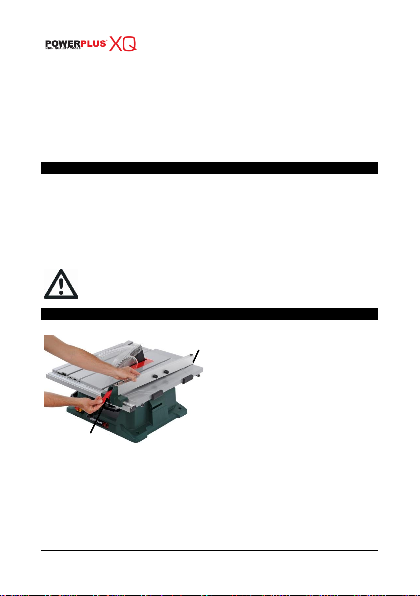
Fig 1
Lift the rip fence handle (a) until the
rear holding clamp (b) is fully
extended.
Place the rip fence on the saw table,
lowering the rear of the fence onto the
table first.
Push down the rip fence handle (a) in
order to lock the rip fence in position.
a
b
lead from lead-based-painted material and,
arsenic and chromium from chemically treated lumber.
Your risk from these exposures varies, depending on how often you do this type of work. To
reduce your exposure to these chemicals: work in well ventilated area and work with approved
safety equipment, such as those dust masks that are specially designed to filter out
microscopic particles.
Use push stick or push block to avoid working with the hands and fingers close to the saw
blade.
Always store the push-stick when it is not in use.
Place a stable support under long workpieces. This allows you to prevent the instability of
the tool.
7 GUIDELINES FOR USING EXTENSION CORDS
Make sure the extension cord is in good condition. When using an extension cord, be sure
to use one that is heavy enough to carry the current that your product will draw. An
undersized cord will cause a drop in line voltage, which will result in loss of power and
overheating.
Make sure your extension cord is properly wired and in good condition. Always replace a
damaged extension cord, or have it repaired by a qualified person before using it. Protect
your extension cords from sharp objects, excessive heat, and damp or wet areas.
Before connecting the motor to the power line, make sure the switch is in the OFF position
and the electric current is rated the same as the current stamped on the motor nameplate.
Running at a lower voltage will damage the motor.
This tool must be grounded while in use in order to protect the operator
from electric shock.
8 ASSEMBLY
8.1 Rip fence (fig. 1)
Copyright © 2010 VARO P a g e | 7 www.varo.com
Page 8

POWXQ5360 EN
Fig 2
When sawing narrow work pieces and for
bevel cuts, the auxiliary rip fence (a)
(aluminum) must be mounted to the rip fence.
Insert the profile rail (b) into the groove on
the short side of the auxiliary rip fence.
Position the profile rail (b) in front of the rip
fence in such a manner that the holes of
both parts are in alignment.
Insert the fastening knobs through the
lateral holes in the rip fence and tighten
them.
Fig 3
When sawing high, narrow work pieces, the
auxiliary rip fence (aluminum) must be
mounted directly to rip fence (d).
Fasten the auxiliary rip fence (a) with the 2
square nuts and the fastening knobs (c)
directly to the rip fence (d).
Fig 4
Unscrew the 6 screws (a) in the table insert. Remove
the table insert by using your spanner to lift it.
Fig 5
Raise the saw blade arbor (e) to its maximum
height by turning the blade raising control handle
counter-clockwise. Remove the arbor nut (b) and
the outer flange (c) from the saw arbor.
Place the saw blade onto the arbor, with the teeth
of the blade pointing DOWN toward the front of the
saw.
Place the flange (c) and the arbor nut (b) onto the
arbor, and hand-tighten the nut. Verify that the saw
blade is firmly seated against the inner flange (d).
NOTE: Verify that the large, flat surfaces of the
flange and the nut face INWARD, toward the saw
blade.
a
8.2 Auxiliary rip fence (fig. 2, fig 3)
8.3 Installing the blade (fig 4, fig 5, fig 6)
Copyright © 2010 VARO P a g e | 8 www.varo.com
Page 9

POWXQ5360 EN
Fig 6
Place the open-ended blade wrench (f) on the flat of
the outer flange (c) in order to prevent the arbor from
turning while tightening.
Tighten the arbor nut by turning it clockwise using the
box-end blade wrench (g)
Fig 7
Use the hand wheel to set the blade to the
maximum height and to set the tilt to 0° on
the bevel scale. Lock the blade with the
bevel locking knob.
After loosening the knob (c), press the
device (a), the splitter (b) should be at the
highest position.
Fig 8
Insert the blade guard assembly (d) into
the splitter bracket, as shown.
Using a straight edge (f), verify whether
the blade guard splitter (e) is aligned with
the saw blade (g), with the straight edge
lying between the teeth of the blade.
Verify that the saw blade, the arbor flange, and the nut are properly seated,
and that the arbor nut is tightened securely.
In order to avoid injury from an accidental start-up, verify that the power
switch is in the “off” position, and that the power cord is not plugged into
the outlet.
8.4 Assembling the blade guard (fig 7, fig 8, fig 9)
Copyright © 2010 VARO P a g e | 9 www.varo.com
Page 10

POWXQ5360 EN
Fig 9
Fig 10
Fig 11
b a c
NOTE: The blade guard and splitter must always be correctly aligned so
that the cut work piece will pass on either side of the splitter without
binding or twisting to the side.
Improper alignment of the splitter can cause “kickback” and serious injury.
8.5 Adjusting riving knife
There must be a clearance of about 5 – 6 mm between the riving knife and the blade teeth
when pushing riving knife toward the blade fully. Adjust the riving knife accordingly by first
loosening clamping nut by hand counterclockwise and then loosening hex bolt
counterclockwise with the hex socket wrench, and measuring the distance. After adjustment,
securely tighten the hex bolt and then the clamping nut clockwise. Always check to see that
the riving knife is secured and that the top blade guard works smoothly before cutting.
The riving knife has been installed before shipment from the factory so that the blade and
riving knife are in a straight line after your simple set-up. Refer to the section titled
“Repositioning riving knife” for the set-up.
CAUTION:
If the blade and riving knife are not aligned properly, a dangerous pinching condition may
result during operation. Make sure the riving knife is positioned between both outer ends
of the blade teeth when viewing from the top. You could suffer serious personal injury
while using the tool without a properly aligned riving knife. If they are not aligned for any
reasons, always have an authorized service center repair it.
When adjusting the riving knife clearance from the blade teeth, always loosen the hex bolt
only after loosening the clamping nut.
8.6 Assembling the table extension wings (fig 10, fig 11)
8.6.1 Side extension table
Unscrew the screws (a) at the end of both extension tubes.
Install the side extension table by sliding the tubes into the 2 holes (b) at the side of the
main table.
Replace the screws (a) back into the tubes to prevent you from pulling the side table too
far out.
You can lock at the wanted position with the 2 locking knobs (c) at the bottom of the main
table.
Copyright © 2010 VARO P a g e | 10 www.varo.com
Page 11

POWXQ5360 EN
Fig 12
Insert the guide rail (a)
of the miter gauge into
one of the guide grooves
(b) of the saw table
intended for this
purpose.
Fig 13
Loosen the locking handle (b) in order to allow the
miter body (c) to rotate freely. Position the miter
body at 90° so that the positive detent secures it in
position. Tighten the locking handle in order to
hold the miter body securely in position.
If the pointer (a) requires adjustment, loosen the
screw that is located under the pointer using a
screwdriver. Adjust the pointer to 90° on the scale,
and then tighten the adjusting screw firmly.
In order to change the angle of the miter gauge,
loosen the locking handle (b) and the rotate the
miter body to the desired angle, as indicated on
the scale. Tighten the locking handle in order to
hold the miter body securely in position.
a b b
8.6.2 Rear extension table
Unscrew the screws (a) at the end of both extension tubes.
Install the rear extension table by sliding the tubes into the 2 holes (b) at the back of the
main table.
Replace the screws (a) back into the tubes to prevent you from pulling the rear extension
table too far out.
You can lock at the wanted position with the 2 locking knobs (c) at the bottom of the main
table.
8.7 Installing the miter gauge (fig 12)
8.8 Adjusting the miter gauge (fig 13)
Copyright © 2010 VARO P a g e | 11 www.varo.com
Page 12

POWXQ5360 EN
Fig. 14
Please use the dust pipe to
attach the vacuum cleaner.
8.9 Installing the vacuum cleaner (fig 14)
9 OPERATING THE MACHINE
For safety reasons, verify that the operator has read the section entitled general safety
guidelines for the table saw before operating this saw. Verify the following before every time
the table saw is used:
1. The blade is tight.
2. The bevel angle locking handle is locked.
3. If ripping, the rip fence locking knob is tight, and the fence is parallel to the miter gauge
groove and the blade.
4. If crosscutting, the miter gauge knob is tight.
5. The blade guard and splitter are in place, and are working properly.
6. Safety glasses are worn.
7. Failure to adhere to these safety rules will greatly increase the chances of injury.
Before using the table saw, polish the tabletop with an automotive polishing wax in order to
keep it clean, and to make it easier to slide the work piece.
There are two basic types of table saw cuts: ripping and crosscutting. Ripping refers to cutting
along the length of the grain and the work piece. Crosscutting refers to either cutting across
the width or across the grain of the work piece. This distinction may be hard to make with man
made materials. Therefore, cutting a piece of material to a different width is ripping, and
cutting across the short dimension is crosscutting. Neither operation can be performed safely
freehand: ripping requires the use of the rip fence, and crosscutting requires the use of the
miter gauge. Never use the rip fence and the miter gauge at the same time during the cutting
operation.
Do not use more than one rip fence or a combination of a miter gauge and a
rip fence at the same time during a cutting operation.
Copyright © 2010 VARO P a g e | 12 www.varo.com
Page 13

POWXQ5360 EN
Fig 16
Fig 17
a b c
a
c b d
9.1 Raising and tilting the blade (fig 15)
Fig 15
9.1.1 Raising
Turn the blade raising control handle (b) CLOCKWISE in order to raise the blade.
It is not necessary to loosen the blade tilting locking knob (a) when raising
or lowering the saw blade.
9.1.2 Tilting
Loosen the blade bevel locking knob (a).
Slide the entire control handle assembly (c) to the desired location.
Tighten the blade bevel locking knob (a). Verify that the locking knob is fully tightened
before attempting a cut.
9.2 ON/OFF paddle switch (fig 16, fig 17)
9.2.1 Switching On
Push the red EMERGENCY OFF button (a) upward and open the yellow safety flap (b).
To start the operation, press the green I-push button (c).
Afterwards, close the safety flap (b) without engaging it.
Copyright © 2010 VARO P a g e | 13 www.varo.com
Page 14

POWXQ5360 EN
Fig 18
This saw is equipped with a reset overload relay
button (a). It is situated at the immediate right of the
paddle switch. The reset button will restart the motor
after it shuts off due to overloading or low voltage.
If the motor stops during operation, move the ON/OFF
paddle switch to the OFF position. Wait approximately
five minutes for the motor to cool down and push the
reset button (a). Now you can switch to the ON
position again.
Fig 19
Fig 20
a a a b c
d
9.2.2 Switching Off
Press the red EMERGENCY OFF button (a) or the red O-push button (d).
9.3 Overload protection (fig 18)
In order to avoid injury and prevent accidental start-up when the reset
button is pushed, the on/off paddle switch should be in the off position, and
the power cord should be unplugged from the outlet while the saw is
cooling down. Overheating may be caused by an under-sized extension
cord, an extension cord that is too long, misaligned parts, or a dull blade.
inspect the saw for proper set-up before using it again.
9.4 Using the table extension wings (fig19, fig 20)
Unlock the table extension wing levers (a) underneath the main table.
Slide the extension tubes in or out until the scale on the tube is positioned at the desired
distance. Lock the table extension wing levers (a).
To adjust the position of the rip fence, loosen the locking handle (c), and place the
auxiliary aluminum fence (d) in position by using the calibration point in red (b).
Tighten the locking handle (c).
Copyright © 2010 VARO P a g e | 14 www.varo.com
Page 15

9.5 Ripping (fig 21)
POWXQ5360 EN
Fig 21
Remove the miter gauge, and secure the rip fence to the table.
Raise the blade until it is approximately 1/8” (3.2 mm) above the top of the work piece.
Place the work piece flat on the table and against the fence so that the larger portion of
the work piece is between the blade and the fence. Keep the work piece approximately 1”
(2.5 cm) away from the blade.
Turn the saw ON, and wait for the blade to reach full speed.
Slowly feed the work piece into the blade by pushing forward on the section of the work
piece that will pass between the blade and the fence
Do not place your thumbs on the table top. Always hold the work piece while the blade is
turning. Do not let go of it in order to reach for the push stick. When both thumbs touch the
front edge of the table, complete the cut using a push stick.
Always use the push stick when performing ripping operations.
Continue to push the work piece with the push stick until it passes the blade guard and
clears the rear of the table.
Do not pull the work piece backward while the blade is turning. Turn the switch OFF, and
unplug the power cord. Wait until the blade comes to a complete stop and slide the work
piece out.
Copyright © 2010 VARO P a g e | 15 www.varo.com
Page 16

POWXQ5360 EN
Fig 23
9.6 Bevel ripping (fig 22)
Fig 22
Bevel ripping is the same as ripping, except that the blade bevel angle is set to an angle other
than “0”.
The workpiece and the fence must be on the right side of the blade when
cutting.
9.7 Ripping small pieces
Avoid injury caused by contact with the blade. Do not use this saw to make
through-cuts that are narrower than 1/2” (13 mm).
It is not safe to rip small pieces. Instead, rip a larger piece in order to obtain the size of the
desired piece.
When ripping a small work piece, it is not safe to place the hand between the blade and
the rip fence. Use one or more push sticks to push the work piece completely past the
blade.
9.8 Crosscutting (fig 23, fig 24)
Copyright © 2010 VARO P a g e | 16 www.varo.com
Page 17

POWXQ5360 EN
Fig 24
Fig 25
Adjust the blade to the desired
angle, and then tighten the blade
bevel locking knob.
Tighten the miter locking handle at
90°.
Hold the work piece firmly against
the face of the miter gauge
throughout the cutting operation.
First unlock the sliding table by moving the transport lock and unscrewing the screw nut
below the table.
Remove the rip fence and place the miter gauge in the miter gauge groove on the table.
Raise the blade until it is approximately 1/8” (3.2 mm) above the top of the work piece.
Hold the work piece firmly against the miter gauge, with the path of the blade in line with
the desired cutting line. Move the work piece to within 1” (2.5 cm) of the blade.
Start the saw, and wait for the blade to reach full speed. Do not stand directly in line with
the saw blade’s path. Instead, stand on the side where the cut is being made.
Keep the work piece against the face of the miter gauge and flat against the table. Slowly
push the sliding table with the work piece through the blade.
Do not attempt to pull the work piece backward while the blade is turning. Turn the switch
OFF, and wait until the blade has come to a complete stop before carefully sliding the
work piece out.
In order to avoid instability, always place the larger surface of the
workpiece on the table when crosscutting and/or bevel crosscutting.
9.9 Bevel crosscutting 0° - 45° blade bevel & 90° miter angle (fig25)
This operation is the same as crosscutting, except that the blade is at a bevel angle other than
0°.
Copyright © 2010 VARO P a g e | 17 www.varo.com
Page 18

POWXQ5360 EN
Fig 26
Set the miter gauge to the
desired angle.
Set the blade bevel to the
desired bevel angle, and tighten
the blade bevel locking knob.
Hold the work piece firmly
against the face of the miter
gauge throughout the cutting
operation.
Fig 27
Set the blade to a 0° bevel angle,
and tighten the blade bevel
locking knob.
Set the miter gauge to the desired
miter angle, and secure it in
position by tightening the miter
gauge locking handle.
Hold the work piece firmly against
the face of the miter gauge
throughout the cutting operation.
Mains supply
230-240 V ~ 50 Hz
Rated input
1800W S6
No load speed
4500min-1
Tilting range
0-45°
Max. cutting depth
90°
80mm
45°
55mm
Table size
645x530mm
Table size with extensions
850x860mm
Connection cable
2m
Blade
254x30x2.8mm, 40T
Safety class
II / double insulated
9.10 Compound miter crosscutting 0° - 45° blade bevel & 0° - 45° miter angle (fig 26)
This sawing operation combines a miter angle with a bevel angle.
9.11 Mitering: 0° - 45° miter angle (fig 27)
This operation is the same as crosscutting, except that the miter gauge is locked at an angle
other than 90°.
10 TECHNICAL DATA
Copyright © 2010 VARO P a g e | 18 www.varo.com
Page 19

POWXQ5360 EN
Weight
28.5 kg
Acoustic pressure level LpA
91 dB(A)
K = 3 dB(A)
Acoustic power level LwA
104 dB(A)
K = 3 dB(A)
Sympton
Possible causes
Corrective action
The saw will not start
The saw is not plugged in.
The fuse has blown or the
circuit breaker has tripped.
The cord is damaged.
Plug in the table saw.
Replace the fuse or reset the
circuit breaker.
Have the cord replaced by a
qualified electrician.
The saw does not make
accurate 45° or 90° rip
cuts
The positive stop is not
adjusted correctly.
Check the blade with the square
and adjust the positive stop.
The blade tilt pointer is not
set correctly.
Check the blade with the square
and adjust the positive to zero.
The rip fence is not properly
aligned.
Align the rip fence with the miter
gauge slot.
11 SOUND EMISSION
Noise emission values measured according to relevant standard.
ATTENTION ! The sound power pressure may exceed 85 dB(A), in this case
individual hearing protection must be worn.
12 CLEANING AND MAINTENANCE
Before performing any work on the equipment, pull the power plug.
12.1 Cleaning
Keep the ventilation slots of the machine clean to prevent overheating of the engine.
Regularly clean the machine housing with a soft cloth, preferably after each use.
Keep the ventilation slots free from dust and dirt.
If the dirt does not come off use a soft cloth moistened with soapy water.
Never use solvents such as petrol, alcohol, ammonia water, etc. These solvents may
damage the plastic parts.
Make sure no water can reach the inside of the power tool!
12.2 Lubrication
All motor bearings are permanently lubricated at the factory, and do not require any additional
lubrication. Use graphite or silicone to lubricate all mechanical parts of the table saw where a
pivot or threaded rod is present. Dry lubricants do not hold sawdust like oil or grease.
13 INFORMATION ABOUT TRANSPORTING AND LIFTING
POSITIONS
When transporting the machine use only transportation devices and do never use guards
for handling, lifting or transportation.
During transportation the upper part of the saw blade should be covered; for example by
the guard.
Always lift your tool at the bottom plate with two persons to avoid back injuries.
14 TROUBLESHOOTING GUIDE
Copyright © 2010 VARO P a g e | 19 www.varo.com
Page 20

POWXQ5360 EN
Sympton
Possible causes
Corrective action
The material pinches
the blade when ripping
The rip fence is not aligned
with the blade.
Check and adjust the rip fence.
The wood is warped, or the
edge that is against the fence
is not straight.
Select another piece of wood.
The material binds on
the splitter
The splitter is not aligned
correctly with the blade.
Check and align the splitter with
the blade.
The saw makes
unsatisfactory cuts
The blade is dull.
Replace the blade.
The blade is mounted
backwards.
Turn the blade around.
There is gum or pitch on the
blade.
Remove the blade and clean it
with turpentine and coarse steel
wool.
The blade is not appropriate
for the work that is being
done.
Change the blade.
There is gum or pitch on the
table causing erratic feeding.
Clean the table with turpentine
and coarse steel wool and apply a
coat of automotive polishing wax.
The material kicks back
from the blade
The rip fence is out of
alignment.
Align the rip fence with the miter
gauge slot.
The splitter is not aligned
correctly with the blade.
Align the splitter with the blade.
The work piece is being fed
without the rip fence.
Install and use the rip fence.
The splitter is not in place.
Install and use the splitter (with
the guard)
The blade is dull.
Replace the blade.
The operator is letting go of
the material before it has
passed the saw blade.
Push the material all the way past
the saw blade before releasing
the work piece.
The miter angle locking knob
is loose.
Tighten the knob.
The blade does not
raise or tilt freely
There is sawdust and/or dirt
in the raising and tilting
mechanisms.
Brush or blow out any loose dust
and dirt.
The blade does not
reach full speed
The extension cord is too
light or too long.
Replace with the proper size of
extension cord.
The voltage from the outlet is
too low.
Contact the electricity supplier.
The saw vibrates
excessively
The saw is not mounted
securely to the workbench.
Tighten all mounting hardware.
The stand is on an uneven
surface.
Reposition the table saw on a flat
level surface.
The blade is damaged.
Replace the blade.
Copyright © 2010 VARO P a g e | 20 www.varo.com
Page 21

POWXQ5360 EN
15 WARRANTY
This product is warranted for a 5-year period effective from the date of purchase by the
first user.
This warranty covers all material or production flaws. It does not include defective parts
subject to normal wear & tear such as bearings, brushes, cables, and plugs, or
accessories such as drills, drill bits, saw blades, etc. ; damage or defects resulting from
maltreatment, accidents or alterations; nor the cost of transportation.
At the same time, no claim can be made on the warranty if the damage of the device is the
result of negligent maintenance or overload.
Definitely excluded from the warranty is damage resulting from fluid permeation, excessive
dust penetration, intentional damage (on purpose or by gross carelessness), inappropriate
usage (use for purposes for which the device is not suitable), incompetent usage (e.g. not
following the instructions given in the manual), inexpert assembly, lightning strike,
erroneus net voltage. This list is not exhaustive.
Acceptance of claims under warranty can never lead to the prolongation of the warranty
period nor commencement of a new warranty period in case of a device replacement.
Devices or parts which are replaced under the warranty therefore remain the property of
Varo NV.
We reserve the right to reject a claim whenever the purchase cannot be verified or when it
is clear that the product has not been properly maintained. (Clean ventilation slots, carbon
brushes serviced regularly, etc.).
Your purchase receipt must be kept as proof of date of purchase.
Your appliance must be returned undismantled to your dealer in an acceptably clean state,
(in its original blow-moulded case if applicable to the unit), accompanied by proof of
purchase.
16 ENVIRONMENT
Should your machine need replacement after extended use, do not put it in the
domestic waste but dispose of it in an environmentally safe way.
Waste electrical products should not be disposed of with household waste. Please
recycle where facilities exist. Check with your Local Authority or retailer for
recycling advice.
Copyright © 2010 VARO P a g e | 21 www.varo.com
Page 22

POWXQ5360 EN
17 DECLARATION OF CONFORMITY
VARO N.V. - Joseph Van Instraat 9 - BE2500 Lier - BELGIUM, declares that,
Is in conformity with the essential requirements and other relevant provisions of the applicable
European Directives, based on the application of European harmonized standards. Any
unauthorized modification of the apparatus voids this declaration.
European Directives (including, if applicable, their amending directives):
European harmonized standards, and their amendments:
The undersigned acts on behalf and under the power of attorney of the company
management,
Product: Table saw 1800W
Trade mark: POWERplus
Model: POWXQ5360
2006/95/EC The Low Voltage Directive
2004/108/EC The Electromagnetic Compatibility Directive
2006/42/EC The Machinery Directive
2000/14/EC The Outdoor Noise Directive
LwA = 104dB
EN61029-1 : 2009
EN61029-2-1 : 2009
EN55014-1 : 2006
EN55014-2 : 1997
EN61000-3-2 : 2006
EN61000-3-3 : 1995
Philippe Vankerkhove
Certification Manager
Date : 19/07/2010
Copyright © 2010 VARO P a g e | 22 www.varo.com
 Loading...