

Page 1
POWXG9006
1
2
3
4
5
APPLIANCE .................................................................................... 3
DESCRIPTION ................................................................................ 3
PACKAGE CONTENT LIST ............................................................ 3
SYMBOLS ....................................................................................... 4
STANDARDIZED SAFETY WARNINGS FOR GASOLINE HIGH
EN
PRESSURE WASHERS .................................................................. 4
6
7
7.1
7.2
8
8.1
8.2
9
9.1
9.2
9.3
9.4
9.5
9.6
9.6.1 0° nozzle (colored red) ........................... .................................................................. 8
9.6.2 15° nozzle (colored yellow) ...................................................................................... 8
9.6.3 40° nozzle (colored white) ........................ ................................................................ 8
9.6.4 Low pressure nozzle (colored black) ........................................................................ 8
9.7
9.8
10
10.1
10.2
10.3
10.4
SAFETY WARNINGS GASOLINE .................................................. 4
SAFETY FEATURES ...................................................................... 5
Thermal relief valve ............................................................................................... 5
Safety lock off latch ............................................................................................... 5
ASSEMBLY INSTRUCTIONS ......................................................... 5
Attach handle and hooks ...................................................................................... 5
Installing the wheels .............................................................................................. 5
BEFORE OPERATION ................................................................... 6
Add oil to the engine crankcase ........................................................................... 6
Add fuel to fuel tank .............................................................................................. 6
Connect high pressure hose to spray gun and pump. ........................................ 6
High pressure lance safety lock ........................................................................... 7
Connecting the hose ............................................................................................. 7
Adjusting the spray pattern .................................................................................. 8
Connect the nozzle ................................................................................................ 8
Using the detergent facility ................................................................................... 9
OPERATING INSTRUCTIONS ....................................................... 9
Pressure washer location...................................................................................... 9
Start-up procedure ................................................................................................ 9
Start engine .......................................................................................................... 10
Stop the engine .................................................................................................... 11
Copyright © 2013 VARO
P a g e | 1
www.varo.com
Page 2

POWXG9006
11
TECHNICAL DATA ....................................................................... 12
12
SOUND EMISSION ....................................................................... 12
13
CLEANING AND MAINTENANCE ............................................... 13
13.1
Clearing a blockage ............................................................................................. 13
13.2
Routine maintenance ........................................................................................... 13
13.2.1 Spark plug ............................................................................................................. 13
13.2.2 Engine oil replacement .......................................................................................... 13
13.2.3 Air filter .................................................................................................................. 14
13.2.4 Fuel tank filter ........................................................................................................ 14
14
STORAGE ..................................................................................... 14
15
PREPARATION FOR WINTER AND LONG TERM STORAGE .. 14
16
TROUBLE SHOOTING ................................................................. 15
17
WARRANTY .................................................................................. 15
18
ENVIRONMENT ............................................................................ 16
19
DECLARATION OF CONFORMITY ............................................. 16
EN
Copyright © 2013 VARO
P a g e | 2
www.varo.com
Page 3
POWXG9006
GASOLINE PRESSURE WASHER
POWXG9006
1 APPLIANCE
Your gasoline high pressure cleaner has been designed for outdoors cleaning. Cleaning of:
machines, vehicles, structures, tools, facades, terraces, gardening tools,…
Danger! Risk of injury! Follow the respective safety regulations when
operating at gas stations or other dangerous areas. Please do not let
mineral oil contaminated waste water reach soil, water or the sewage
system. Perform engine cleaning and bottom cleaning therefore only on
specified places with an oil trap.
Warning! Read this manual and the general safety instructions carefully
before using the machine, for your own safety.
2 DESCRIPTION
Picture 1
1. Handle
2. Nozzles
3. Accessory Tray
4. Lance Hook
5. Safety lock
6. Trigger gun
7. High pressure hose (7,5m)
8. Hose hook
9. Fuel tank
10. Carriage bolts
11. Exhaust silencer
12. Spray wand
13. Engine
14. Oil fill cap
15. Wheel
16. Air filter
17. Recoil starter cord
18. Engine recoil starter
Picture 2
19. Throttle control level
20. Choke
21. Fuel lever
Picture 3
22. ON/OFF switch
23. Detergent filter
24. High pressure outlet
25. Detergent suction tube
26. Water inlet connector
EN
3 PACKAGE CONTENT LIST
Remove all packaging materials.
Remove remaining packing and package inserts (if included).
Check that the package contents are complete.
Check the appliance, the power cord, the power plug and all accessories for
transportation damage.
Keep the packing materials as far as possible till the end of the warranty period. Dispose
it into your local waste disposal system afterwards.
WARNING: Packaging materials are not toys! Children must not play with
plastic bags! Danger of suffocation!
1. Pneumatic tire (2)
2. Gun (1)
3. Lance (1)
4. High Pressure hose 7,5m
5. Water Inlet Connecter (1)
6. Spark Plug Spanner (1)
Copyright © 2013 VARO
P a g e | 3
7. Nozzle Cleaning Tool (1)
8. 5mm Hex key (1)
9. 10-13 wrench 1)
10. Gun (self assembly) (1set)
11. Hose (self assembly) (1set)
12. Operating Instruction manual (1)
www.varo.com
Page 4
13. Manual of engine (1)
If any parts are missing or damaged, please contact your dealer.
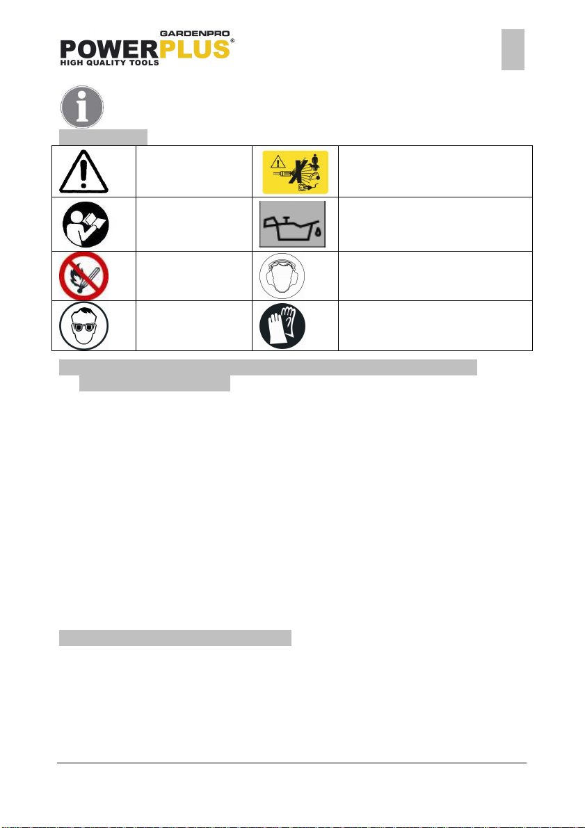
4 SYMBOLS
Warning danger
POWXG9006
The jet must not be directed at
persons, pets, live electrical
equipment or the appliance itself.
EN
Read manual before
usage!
Flammable, do not
smoke near the
pressure washer.
Wear eye protection
Engine will not start or will shut
down if the oil level is low.
Wear ear protection
Wear gloves
5 STANDARDIZED SAFETY WARNINGS FOR GASOLINE HIGH
PRESSURE WASHERS
WARNING: This appliance has been designed for use with the cleaning agent supplied or
recommended by the manufacturer. The use of other cleaning agents or chemicals may
adversely affect the safety of the appliance.
WARNING: Do not use the appliance within range of persons unless they wear protective
clothing
WARNING: High Pressure jets can be dangerous if subject to miss use. The jet must not be
directed at persons, live electrical equipment or the appliance itself.
Do not direct the jet against yourself or others in order to clean shoes or clothes.
To ensure appliance safety, use only original spare parts from the manufacturer or approved
by the manufacturer.
WARNING: High Pressure hoses, fittings, and couplings are important for the safety of the
appliance. Use only fittings and couplings recommended by the manufacturer.
Do not use the appliance, if a supply cord or important parts are damaged, e.g. safety devices,
high pressure hoses, trigger gun.
WARNING: Incorrect fuels shall not be used as they may prove hazardous.
WARNING: Do not use combustion engine powered appliances indoors unless adequate
ventilation is assessed by national labour authorities.
WARNING: Ensure that any exhaust emissions are not in the vicinity of air intakes.
6 SAFETY WARNINGS GASOLINE
WARNING: Use extra care in handling fuels. They are flammable and the vapours are
explosive. The following points must be observed.
Use only an approved container.
Never remove the fuel cap or add fuel with the power source running. Allow engine
exhaust components to cool before refuelling.
Do not smoke.
Never refuel the machine indoors.
Never store the machine or fuel containers inside, where is an open flame, such as a
water heater.
Copyright © 2013 VARO
P a g e | 4
www.varo.com
Page 5
If fuel is spilled, do not attempt to start the power source, but move the machine away
POWXG9006
from the area of spillage before starting.
Always replace and securely tighten the fuel cap after refuelling.
If the tank is drained, this should be done outdoors.
EN
7 SAFETY FEATURES
7.1 Thermal relief valve
A thermal relief valve is provided to protect the pump from overloading if the spray gun is
closed for an extended length of time or the nozzle becomes plugged. However, it is intended
to be used as a backup system and avoid the overheating of the pump.
Switch the pressure washer "OFF", if it will not be used for longer than five minutes. This
reduces wear, prevents fuel consumption and extends the live of the pump by avoiding heat.
7.2 Safety lock off latch
To prevent accidental discharge of high pressure water, the safety lock (picture 1, part 5) on
the trigger should be engaged whenever the pressure washer is not in use (refer to operating
instruction).
8 ASSEMBLY INSTRUCTIONS
Remove all packaging materials from the unit. Check the main unit, its components and all
accessories for loss and transport damages.
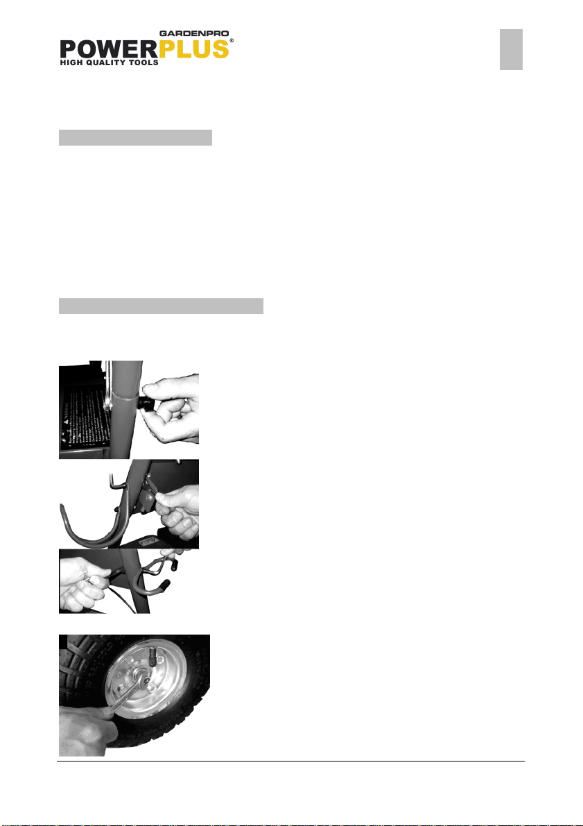
8.1 Attach handle and hooks
Attach the handle (picture 1, part 1) and accessory
tray (picture 1, part 3) to the frame of the pressure
washer. Insert carriage bolts (picture 1, part 10)
through holes from outside of unit and attach a
knob from inside of unit. Tighten by hand.
Fit the hose (picture 1, part 8) and lance hooks
(picture 1, part 4) to the upper handle.
8.2 Installing the wheels
Before you fix the wheels (picture 1, part 15) you
have to loosen a screw to take out the axle. Fit a
wheel to the axle and secure using the locking nut
provided.
Copyright © 2013 VARO
P a g e | 5
www.varo.com
Page 6

POWXG9006
9 BEFORE OPERATION
To prepare your pressure washer for operation, you will need to perform these tasks:
Add oil to engine crankcase.
Add fuel to fuel tank.
Connect high pressure hose to spray gun and pump.
Connect water supply to pump.
Attach nozzle extension to spray gun.
Note: the engine and pump on your new pressure washer will often have an improved
performance after a break of several hours.
9.1 Add oil to the engine crankcase
Do not attempt to start the pressure washer
without filling the engine crank case (picture1, part
14) with the proper amount and type of oil (see
technical data). In delivery status the pressure
washer has no oil inside the engine crank case.
Operating the unit without oil will cause engine
damage. Place the machine on a level surface
and remove the oil filler cap.
Add engine oil to at least half of the dipstick
9.2 Add fuel to fuel tank
EN
The pressure washer is powered by a four-stroke
engine, which uses unleaded petrol fuel.
Use a suitable funnel to fill in the fuel to the
engines fuel tank (picture 1, part 9). Do not spill
any fuel or overfill the tank. The fuel tank should
not be filled above the top of the fuel filter.
9.3 Connect high pressure hose to spray gun and pump.
Fit the lance to the gun (picture 1, part 6). Grip the
end of the gun and screw the lance onto the gun
ensuring it is tight. Do not over tighten as this
could damage both the connectors.
Copyright © 2013 VARO
P a g e | 6
www.varo.com
Page 7

POWXG9006
Connect the high pressure hose connector to the
connector on the underside of the gun assembly
ensuring that it is tight. Do not over tighten as this
could damage both the connectors.
9.4 High pressure lance safety lock
In order to prevent accidental operation of the
high-pressure lance, the gun is fitted with a safety
lock. To engage the safety lock (picture1, part 5)
release the trigger and engage the safety lock
between the trigger and the gun body.
9.5 Connecting the hose
The water inlet connector (picture 3, part 26) is fitted with a particle filter.
Do not run the unit without filter.
Based on the water quality the filter must be checked and cleaned from time to time.
In case there are dirt particles in the water supply, the filter must be cleaned before each use.
Otherwise the performance of the unit will be decreased or the pump might get damaged.
EN
Screw the male, water inlet connector (picture 3,
part 26) onto the pressure washer water inlet.
Fit a female hose connector to your hose pipe and
then connect the female connector onto the male
connector.
Connect the high-pressure hose to the delivery
pipe outlet (picture 3, part 24). Turn on the water
supply and squeeze the gun trigger (picture 1, part
6) until the water flows in a steady stream through
the lance. Do not use water which exceeds 40°C.
Copyright © 2013 VARO
P a g e | 7
www.varo.com
Page 8

POWXG9006
9.6 Adjusting the spray pattern
Warning: Always ensure that the wand (picture 1, part 12)is fixed correctly. Otherwise it could
be injected under high pressure when operating the gun, possibly causing injury or damage.
You have the choice of 4 different colour coded
nozzles (picture 1, part 2) giving you different
spray patterns to choose from:
9.6.1 0° nozzle (colored red)
This nozzle delivers a pinpoint stream and is extremely powerful. It covers a very small area of
cleaning. This nozzle should only be used on surface that can withstand this high pressure
such as metal or concrete. Do not use on wood.
9.6.2 15° nozzle (colored yellow)
This nozzle delivers a powerful 15 degree spray pattern for intense cleaning of small areas.
This nozzle should only be used on areas that can withstand the high pressure from this
nozzle.
9.6.3 40° nozzle (colored white)
This nozzle delivers a 40 degree spray pattern and a less powerful stream of water. It covers a
wide area of cleaning. this nozzle should be used for most general cleaning jobs.
EN
9.6.4 Low pressure nozzle (colored black)
This nozzle is used to apply chemicals or cleaning solutions. It has the least power stream.
Note:
Due to material and workmanship differences high pressure streams can damage patio paving
slabs. Try on a small test area first. If necessary adjust the pressure by changing nozzles or
slowing down the engine speed
9.7 Connect the nozzle
Copyright © 2013 VARO
Connect the nozzle to the lance using the quick release
connector this allows the quick and easy changing of
nozzles. To connect a nozzle slide the collar back towards
the gun, push the nozzle into the end of the lance.
Release the collar to lock the nozzle into position. To
disconnect a nozzle slide the collar back towards the gun,
the nozzle can now be removed.
Note: please be sure that you crosscheck the correct
connection of the nozzle.
Warning: the nozzle is not properly fixed when the collar
doesn’t slide back. Push the nozzle with high force into
the opening, otherwise the collar doesn’t slide back by
itself and the nozzle is shot out.
P a g e | 8
www.varo.com
Page 9

9.8 Using the detergent facility
POWXG9006
Fill a suitable container with pressure washer detergent. Do not use washing up liquid as it
contains salt. We recommend the use of a good quality pressure washer detergent for use
with this pressure washer. Please follow the instructions on the container.
Most automobile detergents are a combination of a detergent and a wax solution, (wash/wax
liquid). These tend to be a thick viscous liquid. The viscosity (thickness) of the detergent will
increase in cold weather. It is recommended that this type of detergent is diluted with warm
water before filling the container. When using combination wash and wax solutions we
recommend that they are diluted before use. As a general guide we would recommend a
dilution rate of 50/50. However a trial and error process would determine the ideal dilution rate
for a particular detergent.
Notes:
A thick viscous detergent would not flow freely from the detergent tank and the residue
would cause a blockage in the detergent flow system.
After using the detergent facility it should be flushed out thoroughly using copious amounts
of water.
To activate detergent delivery, fit the black low
pressure nozzle to the end of the lance. Submerge
the end of the detergent suction tube (picture 3,
part 25) into your container of pressure washer
detergent. Suction and mixing will occur
automatically as the water flows through the
pump.
EN
10 OPERATING INSTRUCTIONS
10.1 Pressure washer location
Locate the pressure washer on a solid and level surface so that the engine and pump
crankcase oil lubricate components properly. Avoid areas where puddles are pounded.
Slippery surfaces can cause injuries.
Locate the machine in a well-ventilated area and away from flammable materials or fumes.
Be sure ventilation warnings are observed. Keep pressure washer at least 18”away from
flammable materials.
Locate the machine in a way, that the operator has easy access to the pressure washer
and its controls. Locate the machine so that it is protected from external damage.
To prevent damage and excessive hose wear; locate the pressure washer so that the
hose does not cross traffic areas.
10.2 Start-up procedure
Remove all dirt or foreign matter from the gun outlet and the male connector.
Insert the nozzle into the gun.
Start engine.
Warning: lf the wand is not securely locked into place. It could be injected under high pressure
when operation the gun, possibly causing injury or damage.
Copyright © 2013 VARO
P a g e | 9
www.varo.com
Page 10

10.3 Start engine
POWXG9006
Turn the fuel lever (picture 2, part 21) to the ON
position.
Set the choke lever (picture 2, part 20) to the ON
position.
Turn the engine ON/OFF switch (picture 3, part
22) to the ON position
Hold down the engine firmly with one hand on the
frame. With the other hand grip the recoil starter
cord (picture 1, part 17) handle and pull slowly
until resistance is felt indicating that the recoil
starter (picture 1, part 18) is engaged. When
resistance is felt pull the cord sharply. Continue
this procedure until the engine starts.
EN
When the engine has been successfully started
and is running smoothly return the choke lever
(picture 2, part 20) to the OFF position
Copyright © 2013 VARO
P a g e | 10
www.varo.com
Page 11

10.4 Stop the engine
Warning!
POWXG9006
When the engine is running, the speed can be
adjusted by moving the throttle control lever
(picture2, part 19). When you slide the throttle to
the right the engine will have a lower rotation
speed. To obtain a higher rotation speed you have
to slide the throttle more to the left.
To stop the engine, turn the engine ON/OFF
switch (picture 3, part 22) to the OFF position.
EN
release all remaining pressure by operating the trigger until there is no more pressure in the
appliance and the water flow stops, secure the trigger with the safety lock (picture1, part 5) to
prevent unintentional operation.
Disconnect the lance and drain any residual water from all hoses (picture 1, part 7), carefully
coil the hoses ensuring that they are not kinked or twisted and check for any other damage,
replace any damaged hoses. Damaged hoses can be dangerous under pressure.
After the engine has stopped turn off the water supply to the pressure washer and
When the engine has stopped and before storage,
turn the fuel lever (picture 2, part 21) to the OFF
position
Copyright © 2013 VARO
P a g e | 11
www.varo.com
Page 12

POWXG9006
MOTOR
WATER CONNECTION
PUMP
DIMENSIONS AND WEIGHTS
11 TECHNICAL DATA
Maximum power at 3600 min-1 4.0kW / 3600 min-1
Operating Speed 3400-3500min-1
Fuel tank 3.6l
Fuel Unleaded gasoline
Engine Type OHV 4-stroke
Starting System Recoil
Displacement 163cc
Max. feed temperature 40°C
Min. feed volume 1200 l/h
Min. feed pressure 0.2 Mpa (2 bar)
Max. feed pressure 0.4 MPa (4bar)
Inlet hose length <15m
Inlet hose diameter (inner diameter) 12.8mm (1/2”)
Working pressure 15 MPa
Flow rate 600 l/h
Oil quantity - pump 75 ml
Oil type – pipe engine oil SAE 75W-90
Detergent suck 30-70 l/h
Max. recoil force of hand spray gun 28.87N
EN
Length x width x height 920 x 530 x 560mm
Weight without accessories 35 Kg
12 SOUND EMISSION
Noise emission values measured according to relevant standard. (k=2)
Sound pressure level LpA 94 dB(A)
Sound power level LwA 108 dB (A)
ATTENTION ! The sound power pressure may exceed 85 dB(A), in this case
individual hearing protection must be worn.
MACHINE VIBRATIONS
Hand spray gun <2.5 m/s² K = 1.5 m/s²
Spray lance <2.5 m/s² K = 1.5 m/s²
Copyright © 2013 VARO
P a g e | 12
www.varo.com
Page 13

POWXG9006
EN
13 CLEANING AND MAINTENANCE
13.1 Clearing a blockage
WARNING:
Before checking, adjustments, cleaning or maintaining the pressure washer, the engine must
be stopped and cooled down. Ensure, that the pressure is released completely
If at any time the flow rate reduces splutters or is
inconsistent release the trigger and switch “OFF”
the machine. Squeeze the trigger to relieve any
pressure and check the nozzle in the end of the
lance for any blockage. If a blockage is suspected
use the nozzle cleaning tool to remove any
blockage. It is important that the water nozzle is
checked and cleaned regularly using the nozzle
cleaning tool supplied. Turn the engine off and
disconnect from the water supply before clearing a
blockage.
13.2 Routine maintenance
13.2.1 Spark plug
After every 50 hours of running the spark plug
should be removed. Check the colour of the
deposits on the end of the spark plug it should be
a “Tan” colour. Remove all deposits using a stiff
brush a brass wire brush is ideal. Check the spark
plug gap and adjust if required. The correct gap
should be 0.7 to 0.8mm.
13.2.2 Engine oil replacement
We recommend that the oil be changed after the first 40 hours of use, then once every 100
hours.
Please dispose of used oil in a manner that is compatible with the environment. We suggest
you take used oil in a sealed container to your local recycling centre. Do not throw it in a trash
or pour it on the ground or down a drain.
Copyright © 2013 VARO
Place the machine on a level surface and warm up
the engine for several minutes.
Then stop the engine.
Place a suitable container below the pump to
catch the used oil.
Remove the oil fill cap, oil drain plug and the
washer so that the oil can be completely drained.
You will need to use a tube or other similar device
to prevent the oil leaking onto the frame of the
pressure washer.
Check the oil drain plug, gasket, oil filler cap and
O-ring and if damaged replace.
Reinstall the oil drain plug and the washer. Tighten
the drain plug securely.
Add engine oil to at least half of the dipstick.
Reinstall the oil fill cap securely.
P a g e | 13
www.varo.com
Page 14

13.2.3 Air filter
POWXG9006
After every 100 hours of running or every month,
the air filter (picture 1, part 16) should be
removed, examined for deterioration and cleaned.
Clean the air filter thoroughly using
environmentally friendly water based degreasing
agent. Allow to dry fully then replace the air filter.
Warning! Never run the engine without the air filter
fitted.
13.2.4 Fuel tank filter
After every 150 hours of running or every three
months the fuel tank filter should be removed and
cleaned. Remove the fuel tank filter cap and the
filter, clean the filter thoroughly using
environmentally friendly water based degreasing
agent and re-fit.
EN
14 STORAGE
If the engine (picture 1, part 13) is not to be used or is to be stored for more than one month
the following storage procedure should be carried out. Drain all the fuel from the fuel tank
(picture 1, part 9) and the carburettor ensure that all the fuel has been removed.
Remove the spark plug
Pour approximately one tablespoon full of clean engine oil into the spark plug hole.
With the ignition turned OFF gently pull on the recoil starter cord (picture 1, part 17)
several times. Re-fit the spark plug continue to pull the recoil starter cord until the piston is
on the compression stroke (when resistance is felt) then stop pulling.
Store the pressure washer in a dry well ventilated place under a cover to prevent any dust or
debris from accumulating on the pressure washer.
15 PREPARATION FOR WINTER AND LONG TERM STORAGE
If the pressure washer is not to be used for more than 3 months or if there is a danger of ice or
frost during winter months the pump unit will require protection to prevent seizing and damage
caused by freezing. To protect the pump unit, mix a solution of automotive antifreeze as
recommended on the antifreeze packaging. Carefully pour the solution into the pressure
washer pump inlet. When the solution drains out of the outlet, seal the outlet with a cork or
other suitable bung. Continue to pour the antifreeze solution into the inlet until the pump is full
then seal the inlet with a cork or other suitable bung.
When the pressure washer is to be used for the first time following the antifreeze protection
ensure that all the antifreeze is flushed out of the pump, hose and lance.
When the pressure washer is first started, small leaks may occur from the pump. These will
disappear after a short time.
Copyright © 2013 VARO
P a g e | 14
www.varo.com
Page 15

16 TROUBLE SHOOTING
PROBLEM
CAUSE
ACTION
Kinked inlet and or pressure
POWXG9006
EN
Fluctuating pressure Pump sucking in air
Water leaking from pump Seals worn out Contact customer helpline
The pump does not reach
the required pressure
Pump is running but no
water delivery
Valves dirty, worn out or
seized
Blocked jet
Pump sucking air from
connections or hose
Suction/delivery valves are
clogged
Unload valve is stuck Loosen and re-tighten regulating
Lance or nozzle worn out Check and/or replace
hose
Blocked inlet filter Remove and clean filter
Blocked jet Remove blockage using the nozzle
Check connections are tight.
Remove blockage using jet cleaning
tool
Check tightness of all connections
Clear or replace valves. Have
machine checked by Service Centre
screw
Check, straighten and replace if
required
cleaning tool.
17 WARRANTY
This product is warranted as provided by law for a 36 months period effective from the
date of purchase by the first user.
This warranty covers all material or production flaws excluding : batteries, chargers,
defective parts subject to normal wear & tear such as bearings, brushes, cables, and
plugs, or accessories such as drills, drill bits, saw blades, etc. ; damage or defects
resulting from maltreatment, accidents or alterations; nor the cost of transportation.
Damage and/or defects resulting from inappropriate use also do not fall under the
warranty provisions.
We also disclaim all liability for any bodily injury resulting from inappropriate use of the
tool.
Repairs may only be carried out by an authorised customer service centre for Powerplus
tools.
You can always obtain more information at the number 00 32 3 292 92 90.
Any transportation costs shall always be borne by the customer, unless agreed otherwise
in writing.
At the same time, no claim can be made on the warranty if the damage of the device is the
result of negligent maintenance or overload.
Definitely excluded from the warranty is damage resulting from fluid permeation, excessive
dust penetration, intentional damage (on purpose or by gross carelessness), inappropriate
usage (use for purposes for which the device is not suitable), incompetent usage (e.g. not
following the instructions given in the manual), inexpert assembly, lightning strike,
erroneus net voltage. This list is not exhaustive.
Acceptance of claims under warranty can never lead to the prolongation of the warranty
period nor commencement of a new warranty period in case of a device replacement.
Devices or parts which are replaced under the warranty therefore remain the property of
Varo NV.
We reserve the right to reject a claim whenever the purchase cannot be verified or when it
is clear that the product has not been properly maintained. (Clean ventilation slots, carbon
brushes serviced regularly, etc.).
Your purchase receipt must be kept as proof of date of purchase.
Copyright © 2013 VARO
P a g e | 15
www.varo.com
Page 16

Your appliance must be returned undismantled to your dealer in an acceptably clean state,
POWXG9006
(in its original blow-moulded case if applicable to the unit), accompanied by proof of
purchase.
EN
18 ENVIRONMENT
Should your appliance need replacement after extended use, do not discard it with the
household rubbish but dispose of it in an environmentally safe way.
Please dispose of used motor oil in a manner that is compatible with the environment. We
suggest you take it in a sealed container to your local service station for reclamation. Do not
throw it in the trash or pour it on the ground.
19 DECLARATION OF CONFORMITY
VARO N.V. - Joseph Van Instraat 9 - BE2500 Lier - BELGIUM, declares that,
Is in conformity with the essential requirements and other relevant provisions of the applicable
European Directives, based on the application of European harmonized standards. Any
unauthorized modification of the apparatus voids this declaration.
European Directives (including, if applicable, their amending directives):
European harmonized standards, (including, if applicable, their amendments:
The undersigned acts on behalf and under the power of attorney of the company
management,
Product: High pressure cleaner : Gasoline operated
Trade mark : POWERplus
Model : POWXG9006
2004/108/EC
2006/42/EC
2000/14/EC Annex V LwA = 106dB(A) /108dB(A)
97/68/EC Engine Class = SN3
EDP = 125h
Testing Authority NSAI / Dublin
EN60335-1 : 2002
EN60335-2-79 : 2009
EN55012 : 2007
Philippe Vankerkhove
Certification Manager
Date : 22/08/2012
Copyright © 2013 VARO
P a g e | 16
www.varo.com
 Loading...