

Page 1

POWX075 EN
1 APPLICATION ................................................................................ 3
2 DESCRIPTION (FIG. A) .................................................................. 3
3 PACKAGE CONTENT LIST ............................................................ 3
4 SYMBOLS ....................................................................................... 4
5 GENERAL POWER TOOL SAFETY WARNINGS ......................... 4
5.1 Work area ............................................................................................................... 4
5.2 Electrical safety ................................................................ ..................................... 4
5.3 Personal safety ...................................................................................................... 5
5.4 Power tool use and care ........................................................................................ 5
5.5 Service .................................................................................................................... 5
6 ADDITIONAL SAFETY INSTRUCTIONS FOR CUT-OFF
MACHINES ...................................................................................... 5
7 ADDITIONAL SAFETY INSTRUCTIONS FOR LASERS ............... 6
8 ASSEMBLY ..................................................................................... 6
8.1 Mounting the machine (fig. A) ............................................................................... 6
8.2 Adjusting the sawing angle (fig. A&B) ................................................................. 6
8.3 Adjusting the bevel angle (fig. A&C) .................................................................... 6
8.4 Checking and adjusting the saw blade depth (fig. C) .......................................... 7
8.5 Replacing the saw blade (fig. D) ........................................................................... 7
8.6 Setting the mitre angle (tig. A) .............................................................................. 7
8.7 Setting the bevel angle (fig. A) .............................................................................. 7
8.8 Setting the groove depth (fig. E) ........................................................................... 7
8.9 Mounting and adjusting the table extenders (fig. F) ............................................ 8
8.10 Mounting and adjusting the vice (fig. G) .............................................................. 8
8.11 Instructions for use ............................................................................................... 8
9 OPERATION.................................................................................... 8
9.1 Switching on and off (fig. A) ................................................................................. 8
9.2 Sliding cut (fig. A&H) ............................................................................................. 8
9.3 Grooving (tig. I) ...................................................................................................... 8
9.4 Dust extraction (fig. J) ........................................................................................... 9
10 CLEANING AND MAINTENANCE ................................................. 9
Copyright © 2014 VARO P a g e | 1 www.varo.com
Page 2

10.1 Cleaning ................................................................................................................. 9
10.2 Lubrication (fig. D) ................................................................................................. 9
11 TECHNICAL DATA ......................................................................... 9
12 NOISE .............................................................................................. 9
13 SERVICE DEPARTMENT ............................................................. 10
14 STORAGE ..................................................................................... 10
15 WARRANTY .................................................................................. 10
16 ENVIRONMENT ............................................................................ 11
17 DECLARATION OF CONFORMITY ............................................. 11
POWX075 EN
Copyright © 2014 VARO P a g e | 2 www.varo.com
Page 3
POWX075 EN
1 Mitre saw + stand
1 hex key
1 pc adjusting ring for saw blade
1 dust bag
1 user manual
2 AAA batteries (laser)
2 extension rods
1 saw blade (mounted)
1 set carbon brush
1 clamp
4 pcs rubber feet
SLIDE COMPOUND MITRE SAW 2000W
POWX075
1 APPLICATION
The tool is intended for accurate straight and Mitre cutting in wood.
It is not designed for commercial use.
WARNING! Read this manual and general safety instructions carefully
before using the appliance, for your own safety. Your power tool should
only be passed on together with these instructions
2 DESCRIPTION (FIG. A)
1. On/off switch
2.
3. Unlock handle machine head
4. Transport handgrip
5. Head lock down knob
6. Lock knob slide mechanism
7. Lock knob mitre angle
8. Groove stop
9. Mounting hole
3 PACKAGE CONTENT LIST
Remove all packing materials
Remove remaining packaging and transit supports (if existing)
Check the completeness of the packing content
Check the appliance, the power cord, the power plug and all accessories for transportation
damages.
Keep the packaging materials as far as possible till the end of the warranty period.
Dispose
it into your local waste disposal system afterwards.
10. Scale for mitre angle
11. Guide fence
12. Saw blade guard
13. Table top
14. Saw slot
15. Scale for bevel angle
16. Lock knob bevel angle
17. Dust extraction connection
WARNING Packing materials are no toys! Children must not play with
plastic bags! Danger of suffocation!
When parts are missing or damaged, please contact your dealer..
Copyright © 2014 VARO P a g e | 3 www.varo.com
Page 4
POWX075 EN
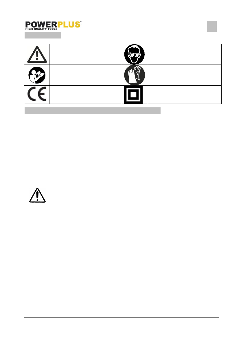
Denotes risk of personal injury
or damage to the tool.
Wear eye protection
Read manual before use
Wear gloves
In accordance with essential
requirements of the European
directive(s)
"Class II - The machine is
double insulated; Earthing wire
is therefore not necessary
4 SYMBOLS
In this manual and/or on the machine the following symbols are used:
5 GENERAL POWER TOOL SAFETY WARNINGS
Read all safety warnings and all instructions. Failure to follow all warnings and instructions may
result in electric shock, fire and/or serious injury. Save all warnings and instructions for future
reference. The term "power tool" in the warnings refers to your mains operated (corded) power
tool or battery operated (cordless) power tool.
5.1 Work area
Keep work area clean and well lit. Cluttered and dark areas invite accidents.
Do not operate power tools in explosive atmospheres, such as in the presence of
flammable liquids, gases or dust. Power tools create sparks which may ignite the dust or
fumes.
Keep children and bystanders away while operating a power tool. Distractions can cause
you to lose control.
5.2 Electrical safety
Always check that the power supply corresponds to the voltage on the
rating plate.
Power tool plugs must match the outlet. Never modify the plug in any way. Do not use any
adapter plugs with earthed (grounded) power tools. Unmodified plugs and matching
outlets will reduce risk of electric shock.
Avoid body contact with earthed or grounded surfaces such as pipes, radiators, ranges
and refrigerators. There is an increased risk of electric shock if your body is earthed or
grounded.
Do not expose power tools to rain or wet conditions. Water entering a power tool will
increase the risk of electric shock.
Do not abuse the cord. Never use the cord for carrying, pulling or unplugging the power
tool. Keep cord away from heat, oil, sharp edges or moving parts. Damaged or entangled
cords increase the risk of electric shock.
When operating a power tool outdoors, use an extension cord suitable for outdoor use.
Use of a cord suitable for outdoor use reduces the risk of electric shock.
If operating a power tool in a damp location is unavoidable, use a residual current device
(RCD) protected supply. Use of an RCD reduces the risk of electric shock.
Copyright © 2014 VARO P a g e | 4 www.varo.com
Page 5

POWX075 EN
5.3 Personal safety
Stay alert, watch what you are doing and use common sense when operating a power
tool. Do not use a power tool while you are tired or under the influence of drugs, alcohol or
medication. A moment of inattention while operating power tools may result in serious
personal injury.
Use safety equipment. Always wear eye protection. Safety equipment such as dust mask,
non-skid safety shoes, hard hat, or hearing protection used whenever conditions require
will reduce personal injuries.
Avoid accidental starting. Ensure the switch is in the off position before plugging in.
Carrying power tools with your finger on the switch or plugging in power tools that have
the switch on invites accidents.
Remove any adjusting key or wrench before turning the power tool on. A wrench or a key
left attached to a rotating part of the power tool may result in personal injury.
Do not overreach. Keep proper footing and balance at all times. This enables better
control of the power tool in unexpected situations.
Dress properly. Do not wear loose clothing or jewellery. Keep your hair, clothing and
gloves away from moving parts. Loose clothes, jewellery or long hair can be caught in
moving parts.
If devices are provided for the connection of dust extraction and collection facilities,
ensure these are connected and properly used. Use of these devices can reduce dust
related hazards.
5.4 Power tool use and care
Do not force the power tool. Use the correct power tool for your application. The correct
power tool will do the job better and safer at the rate for which it was designed.
Do not use the power tool if the switch does not turn it on and off. Any power tool that
cannot be controlled with the switch is dangerous and must be repaired.
Disconnect the plug from the power source before making any adjustments, changing
accessories, or storing power tools. Such preventive safety measures reduce the risk of
starting the power tool accidentally.
Store idle power tools out of the reach of children and do not allow persons unfamiliar with
the power tool or these instructions to operate the power tool. Power tools are dangerous
in the hands of untrained users.
Maintain power tools. Check for misalignment or sticking of moving parts, breakage of
parts and any other condition that may affect the power tool’s operation. If damaged, have
the power tool repaired before use. Many accidents are caused by poorly maintained
power tools.
Keep cutting tools sharp and clean. Properly maintained cutting tools with sharp cutting
edges are less likely to stick and are easier to control.
Use the power tool, accessories and tool bits etc., in accordance with these instructions
and in the manner intended for the particular type of power tool, taking into account the
working conditions and the work to be performed. Use of the power tool for operations
different from intended could lead to a hazardous situation.
5.5 Service
Have your power tool serviced by a qualified repair person using only identical
replacement parts. This will ensure that the safety of the power tool is maintained.
6 ADDITIONAL SAFETY INSTRUCTIONS FOR CUT-OFF MACHINES
Make sure that all devices screening the saw blade are in perfect working order.
Make sure that the saw blade is screened correctly.
Never block the saw blade guard. Repair a jammed saw bladeguard before using the
machine again.
Copyright © 2014 VARO P a g e | 5 www.varo.com
Page 6

Do not use saw blades made of HSS steel.
Do not use bent, deformed or otherwise damaged saw blades.
Do not use saw blades which do not meet the specifications stated in this manual.
Before sawing, remove all nails and other metal objects from the workpiece.
Never start sawing before the saw reaches its full speed.
Securely clamp the workpiece.
Never attempt to saw extremely small workpieces.
Only leave the machine after switching off and when the saw blade has come to a
complete standstill. Pull down the saw head and press in the locking knob.
Never try to slow the saw blade down by exerting pressure on the side.
Before performing maintenance to the machine, always unplug the machine.
7 ADDITIONAL SAFETY INSTRUCTIONS FOR LASERS
POWX075 EN
Warning! The laser beam potentially causes severe eye damage. Never look
or stare directly into the laser beam.
During use, do not point the laser beam at people, directly or indirectly
through reflecting surfaces.
This laser complies with class 2 according to EN 60825-1:1994. The unit includes no
servicing components. Do not open the housing for any reason. If the unit is damaged,
have the damage repaired by an authorized repair agent
8 ASSEMBLY
8.1 Mounting the machine (fig. A)
The machine must be screwed to a workbench.
Mark the position of the mounting holes (9) on the workbench.
Drill holes at each of the marked positions, adjusting the diameter and depth of the holes
to the screws used.
Place the machine on the workbench and insert the screws into the mounting holes.
Firmly tighten the screws.
8.2 Adjusting the sawing angle (fig. A&B)
The default angle between the saw blade and the saw table is 90°.
Use a set square to check that the angle between the saw blade and the table top (13) is
90°. If the angle does not measure 90° adjust as follows:
Loosen the head lock down knob (5) and move the head so the saw blade reaches a 90°
angle.
Loosen the locknut on the adjusting screw (18) and screw the adjusting screw in or out to
achieve a 90° angle. Retighten the locknut.
Tighten the lock knob.
Loosen the screw (19) and adjust the pointer (20) so that it registers 0°. Tighten the screw.
8.3 Adjusting the bevel angle (fig. A&C)
The max. bevel angle is 45°.
Loosen the lock knob (16) and turn the head to the utter bevel angle.
Check the bevel angle using the scale (15). If the angle does not measure 45° adjust as
follows:
Loosen the locknut on the adjusting screw (21) and screw the adjusting screw in or out to
achieve a 45° angle. Retighten the locknut.
Copyright © 2014 VARO P a g e | 6 www.varo.com
Page 7

POWX075 EN
8.4 Checking and adjusting the saw blade depth (fig. C)
Follow the "Instructions for use" to perform a test cut.
If the saw blade does not cut the workpiece completely,adjust as follows:
Loosen the lock nut (22) on the adjusting screw (23).
Turn the adjusting screw to allow the saw blade to achieve the required depth.
Tighten the lock nut.
8.5 Replacing the saw blade (fig. D)
Before replacing the saw blade always unplug the tool. Do not use saw blades
made of HSS steel. Only use saw blades suitable for a speed of at least 6000
min1. Make sure that the spindle diameter and the saw blade bore match.
Only use sharp and undamaged saw blades. Cracked or bent saw blades must be replaced
immediately.
Lock the slide mechanism.
Lock the head of the machine in its highest position.
Keep the unlock handle machine head (3) depressed and turn the lower saw blade guard
(12) fully upward. Place the supplied wrench onto the fixing screw (24).
Depress the lock knob (25) and keep it depressed.
Loosen the fixing screw (24) and remove it.
Remove the outer flange (26), the old saw blade (27), the adapter (28) and the inner
flange (29).
Clean the flanges and the adapter.
Place the inner flange and the adapter.
Place the new saw blade with the teeth pointing in the direction of rotation. See the arrow
on the housing (30).
Place the outer flange on the saw blade.
Mount the fixing screw and tighten it.
Lower the saw blade guard.
8.6 Setting the mitre angle (tig. A)
The mitre angle is left/right infinitely variable between 0° and 45°.
Loosen the lock knob (7).
Set the required mitre angle using the scale (10).
Tighten the lock knob.
8.7 Setting the bevel angle (fig. A)
The bevel angle is infinitely variable between 0° and 45°.
Loosen the lock knob (16).
Set the required bevel angle using the scale (15).
Tighten the lock knob.
8.8 Setting the groove depth (fig. E)
Using the grooving feature, the machine can be used to make crosswise or slant grooves in
workpieces.
Slide the groove stop (8) into position.
Loosen the lock nut (31) on the adjusting screw (32).
Turn the screw in or out to set the groove depth.
Tighten the lock nut.
Slide the groove stop out of the way to cancel the groovingfeature.
Copyright © 2014 VARO P a g e | 7 www.varo.com
Page 8

POWX075 EN
8.9 Mounting and adjusting the table extenders (fig. F)
Using the table extenders you can support long workpieces. The table extenders can be
mounted both to the left and to the right of the machine.
Insert on each side a table extender (33) into the openings in the base of the machine as
shown in the illustration.
Secure each extender by tightening the lock knob (34).
8.10 Mounting and adjusting the vice (fig. G)
The vice can be mounted both on the left-hand and on the right-hand side of the machine.
Loosen the lock knob (35).
Place the vice (36) into one of the mounting holes in the base of the machine as shown in
the illustration.
Tighten the lock knob.
Unscrew the vice far enough to place the workpiece.
Fasten the vice so the workpiece is clamped tightly between the vice and the table top (13).
8.11 Instructions for use
Slide the head of the machine as far backward as possible and fix the head in this position.
Pull out the head lock down knob (5) to raise the head of the machine.
Keep the workpiece pressed to the table and the guide fence.
Make sure that the saw blade has reached full speed before it touches the workpiece.
Depress the head with equal force to allow the saw blade to cut through the workpiece and
enter the table slot.
Do not exert pressure on the saw blade. Allow the machine enough time to cut the
workpiece.
Only raise the head after the saw blade has come to a complete standstill.
9 OPERATION
9.1 Switching on and off (fig. A)
To switch the tool on, keep the lock-off button (2) depressed and press the on/off switch
(1)
To switch the tool off, release the on/off switch (1).
Your POW X075 has a soft start function. Always allow the saw to reach full speed before you
start cutting.
9.2 Sliding cut (fig. A&H)
Using the slide mechanism the cutting capacity can temporarily be enhanced for cutting off wide
workpieces.
Lock the head of the machine in its lowest position.
Loosen the lock knob (6) and slide the head to the front.
Clamp the workpiece in the vice (36).
Follow the "Instructions for use", but keep the machine switched on.
As soon as the head has been fully depressed, push it with equal force to the rear to allow the
saw blade to further cut through the workpiece.
Only raise the head after the saw blade has come to a complete standstill.
9.3 Grooving (tig. I)
Make sure that the groove stop (8) is in position.
Perform a sliding cut as described above to make a groove.
Cancel the grooving feature after use.
Copyright © 2014 VARO P a g e | 8 www.varo.com
Page 9

POWX075 EN
POWX075
Voltage / frequency
230-240 V~50 Hz
Power input
2000 W
No load speed
4200 min-1
Blade size (TCT)
Ø 305 x Ø 30 x 3.0 mm – 80T
Max.cutting capacity
:
0°-90°
310x95(wxh) mm
45"-90°
215x95(wxh) mm
0°-45°
310x60(wxh) mm
45"-45°
215x60(wxh) mm
Acoustic pressure level LpA
99 dB(A)
Acoustic power level LwA
112 dB(A)
aw (Vibration)
1,2 m/s²
K = 1,5 m/s²
9.4 Dust extraction (fig. J)
The dust extraction outlet together with an external vacuum cleaner takes care of the dust
extraction of the working surface.
If necessary, connect an adapter to the connection (17).
Connect a vacuum cleaner to the machine.
If you want to use the dust bag:
Slide the dust bag (37) onto the connection (17).
Regularly empty the dust bag to ensure optimum dust extraction.
10 CLEANING AND MAINTENANCE
Attention !Before performing any work on the equipment, pull the power
plug.
10.1 Cleaning
Keep the ventilation slots of the machine clean to prevent overheating of the engine.
Regularly clean the machine housing with a soft cloth, preferably after each use.
Keep the ventilation slots free from dust and dirt.
If the dirt does not come off use a soft cloth moistened with soapy water.
Never use solvents such as petrol, alcohol, ammonia water, etc. These
solvents may damage the plastic parts.
10.2 Lubrication (fig. D)
From time to time, apply a drop of oil to the thread of the fixing screw (24).
11 TECHNICAL DATA
12 NOISE
Noise emission values measured according to relevant standard. (K=3)
ATTENTION! Wear hearing protection when sound pressure is over 85
dB(A).
Copyright © 2014 VARO P a g e | 9 www.varo.com
Page 10

POWX075 EN
13 SERVICE DEPARTMENT
Damaged switches must be replaced by our after-sales service department.
If the connecting cable (or mains plug) is damaged, it must be replaced by a particular
connecting cable which is available from our service department. Replacement of the
connecting cable must only be carried out by our service department (see last page) or by
a qualified person (qualified electrician).
14 STORAGE
Thoroughly clean the whole machine and its accessories.
Store it out of the reach of children, in a stable and secure position, in a cool and dry
place, avoid too high and too low temperatures.
Protect it from exposure to direct sunlight. Keep it in the dark, if possible.
Don’t keep it in plastic bags to avoid humidity build-up.
15 WARRANTY
This product is warranted for a 36-month period effective from the date of purchase by the
first user.
This warranty covers all material or production flaws excluding : batteries, chargers,
defective parts subject to normal wear & tear such as bearings, brushes, cables, and
plugs, or accessories such as drills, drill bits, saw blades, etc. ; damage or defects
resulting from maltreatment, accidents or alterations; nor the cost of transportation.
Damage and/or defects resulting from inappropriate use also do not fall under the
warranty provisions.
We also disclaim all liability for any bodily injury resulting from inappropriate use of the
tool.
Repairs may only be carried out by an authorised customer service centre for Powerplus
tools.
You can always obtain more information at the number 00 32 3 292 92 90.
Any transportation costs shall always be borne by the customer, unless agreed otherwise
in writing.
At the same time, no claim can be made on the warranty if the damage of the device is the
result of negligent maintenance or overload.
Definitely excluded from the warranty is damage resulting from fluid permeation, excessive
dust penetration, intentional damage (on purpose or by gross carelessness), inappropriate
usage (use for purposes for which the device is not suitable), incompetent usage (e.g. not
following the instructions given in the manual), inexpert assembly, lightning strike,
erroneus net voltage. This list is not exhaustive.
Acceptance of claims under warranty can never lead to the prolongation of the warranty
period nor commencement of a new warranty period in case of a device replacement.
Devices or parts which are replaced under the warranty therefore remain the property of
Varo NV.
We reserve the right to reject a claim whenever the purchase cannot be verified or when it
is clear that the product has not been properly maintained. (Clean ventilation slots, carbon
brushes serviced regularly, etc.).
Your purchase receipt must be kept as proof of date of purchase.
Your appliance must be returned undismantled to your dealer in an acceptably clean state,
(in its original blow-moulded case if applicable to the unit), accompanied by proof of
purchase.
Copyright © 2014 VARO P a g e | 10 www.varo.com
Page 11

POWX075 EN
16 ENVIRONMENT
Should your appliance need replacement after extended use, do not discard it
with the household rubbish but dispose of it in an environmentally safe way.
Waste produced by electrical machine items should not be handled like normal
household rubbish. Please recycle where recycle facilities exist. Check with your
Local Authority or retailer for recycling advice.
17 DECLARATION OF CONFORMITY
VARO N.V. - Joseph Van Instraat 9 - BE2500 Lier - BELGIUM, declares that,
product : Laser Slide Compound Mitre saw
trade mark : POWERplus
model : POWX075
is in conformity with the essential requirements and other relevant provisions of the applicable
European Directives, based on the application of European harmonized standards. Any
unauthorized modification of the apparatus voids this declaration.
European Directives (including, if applicable, their amendments up to the date of signature);
2004/108/EC
2006/42/EC
2011/65/EC
2000/14/EC Annex V LwA 109 dB(A) / 112 dB(A)
European harmonized standards (including, if applicable, their amendments up to the date of
signature);
EN61029-1 : 2009
EN61029-2-9 : 2009
EN55014-1 : 2006
EN55014-2 : 1997
EN61000-3-2 : 2006
EN61000-3-3 : 2008
Keeper of the Technical Documentation : Philippe Vankerkhove, VARO – Vic. Van Rompuy
N.V.
The undersigned acts on behalf of the company CEO,
Hugo Cuypers
Regulatory Affairs – Compliance Manager
Date: 24/10/2013
Copyright © 2014 VARO P a g e | 11 www.varo.com
 Loading...