

Page 1

POWX067 EN
1 APPLICATION .................................................................................. 3
2 DESCRIPTION (FIG A) .................................................................... 3
3 PACKAGE CONTENT LIST ............................................................. 3
4 SYMBOLS ........................................................................................ 4
5 GENERAL POWER TOOL SAFETY WARNINGS .......................... 4
5.1 Working area ........................................................................................................... 4
5.2 Electrical safety ....................................................................................................... 4
5.3 Personal safety ....................................................................................................... 5
5.4 Power tool use and care ......................................................................................... 5
5.5 Service ..................................................................................................................... 5
6 SPECIFIC SAFETY INSTRUCTIONS FOR ANGLE GRINDERS ... 6
7 OPERATION ..................................................................................... 7
7.1 Fitting the auxiliary handle ..................................................................................... 7
7.2 Assembly the protective guard .............................................................................. 7
7.3 Replacing the grinding disc ................................................................................... 8
7.4 Switching on / off .................................................................................................... 9
7.4.1 Switching on ............................................................................................................. 9
7.4.2 Switching off ............................................................................................................. 9
7.5 Adjusting the main handle position ................................................................ ....... 9
8 OPERATON MODES ..................................................................... 10
8.1 Grinding ................................................................................................................. 10
8.2 Splitting ................................................................................................................. 10
9 FLANGE ARRANGEMENTS WHEN USING GRINDING WHEELS
AND CUTTING WHEELS ............................................................... 10
9.1 Flange arrangements when using a depressed centre or straight grinding
9.2 Flange arrangement when using a depressed-centre cutting wheel ................. 11
9.3 Flange arrangement when using a straight cutting wheel ................................. 11
wheel ...................................................................................................................... 10
10 CLEANING AND MAINTENANCE ................................................. 11
10.1 Cleaning................................................................................................................. 11
10.2 Lubrication ............................................................................................................ 11
Copyright © 2010 VARO page | 1 www.varo.com
Page 2

10.3 Replacing Coal Brushes ....................................................................................... 11
11 TECHNICAL DATA ........................................................................ 12
12 SOUND EMISSION ........................................................................ 12
13 SERVICE DEPARTMENT .............................................................. 12
14 STORAGE ...................................................................................... 12
15 WARRANTY ................................................................................... 12
16 ENVIRONMENT ............................................................................. 13
17 DECLARATION OF CONFORMITY .............................................. 13
POWX067 EN
Copyright © 2010 VARO page | 2 www.varo.com
Page 3

POWX067 EN
ANGLE GRINDER
POWX067
1 APPLICATION
This machine is developed for grinding and roughing of metal and stone. With help of the
correct accessories the machine can also be used for brushing and sanding. It is not designed
for commercial use.
WARNING! For your own safety, read this manual and the general safety
instructions carefully before using the appliance. Your power tool should
only be given to other users together with these instructions.
2 DESCRIPTION (FIG A)
1. Lock lever for protection guard
2. Spindle lock button
3. Attachment point for auxiliary handle (Above)
4. Main handle
5. On/Off switch
6. Safety switch
7. Position regulator button for main handle
8. Auxiliary handle
9. Guard
10. Grinding disc (not included)
3 PACKAGE CONTENT LIST
§ Remove all packaging materials.
§ Remove remaining packaging and packing inserts (if included).
§ Check that the package contents are complete.
§ Check the appliance, the power cord, the power plug and all accessories for transportation
damage.
§ Keep the packaging materials as far as possible until the end of the warranty period. Then
take it to your local waste disposal system.
WARNING! Packaging materials are not toys! Children must not play with
plastic bags! There is a danger of suffocation!
1 x angle grinder 2450W - 230mm
1 x auxiliary handle
1 x pin spanner
If any parts are missing or damaged, please contact your dealer.
Copyright © 2010 VARO page | 3 www.varo.com
1 x hex key
1set carbon brushes
Instruction manual
Page 4
POWX067 EN
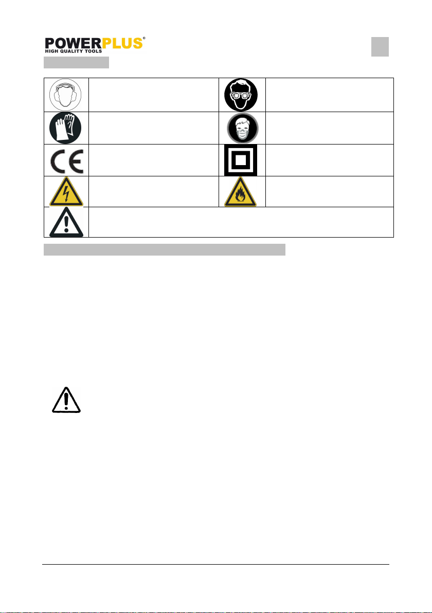
4 SYMBOLS
In this manual and/or on the machine the following symbols are used:
Always wear hearing protection.
Always wear protective gloves.
In accordance with essential
requirements of the European
directive(s)
Indicates electrical shock
hazard.
Denotes risk of personal injury or damage to the tool.
Always wear safety goggles.
Always wear a dust mask.
Class II - The machine is
double insulated; Earthing wire
is therefore not necessary.
Risk of fire!
5 GENERAL POWER TOOL SAFETY WARNINGS
Read all safety warnings and instructions. Failure to heed warnings and follow instructions
may result in electric shock, fire and/or serious injury. Keep safety warnings and instructions
for future reference. The term "power tool" in the safety warnings refers to your mainsoperated (corded) power tool or battery-operated (cordless) power tool.
5.1 Working area
§ Keep working area clean and well lit. Untidy and dark areas can lead to accidents.
§ Do not operate power tools in potentially explosive surroundings, for example, in the
presence of inflammable liquids, gases or dust. Power tools create sparks which may
ignite the dust or fumes.
§ Keep children and bystanders at a distance when operating a power tool. Distractions can
cause you to lose control of it.
5.2 Electrical safety
Always check that the power supply corresponds to the voltage on the
rating plate.
§ Power tool plugs must match the outlet. Never modify the plug in any way. Do not use
adapter plugs with earthed power tools. Unmodified plugs and matching outlets will
reduce the risk of a lethal electric shock.
§ Avoid body contact with earthed surfaces such as pipes, radiators, kitchen ranges and
refrigerators. There is an increased risk of a lethal electric shock if your body is earthed.
§ Do not expose power tools to rain or wet conditions. If water gets inside a power tool, it will
increase the risk of a lethal electric shock.
§ Do not damage the cord. Never use the cord for carrying, pulling or unplugging the power
tool. Keep the cord away from heat, oil, sharp edges or moving parts. Damaged or
entangled cords increase the risk of a lethal electric shock.
§ When operating a power tool outdoors, use an extension cable suitable for outdoor use.
Using a cord suitable for outdoor use reduces the risk of a lethal electric shock.
Copyright © 2010 VARO page | 4 www.varo.com
Page 5

§ If operating a power tool in a damp location is unavoidable, use a power supply protected
POWX067 EN
by a residual current device (RCD). Using an RCD reduces the risk of a lethal electric
shock.
5.3 Personal safety
§ Stay alert, watch what you are doing and use common sense when operating a power
tool. Do not use a power tool when you are tired or under the influence of drugs, alcohol or
medication. A moment of inattention when operating a power tool may result in serious
personal injury.
§ Use safety equipment. Always wear eye protection. Using safety equipment such as a
dust mask, non-skid safety shoes, a hard hat, or hearing protection whenever it is needed
will reduce the risk of personal injury.
§ Avoid accidental starts. Ensure the switch is in the off position before inserting the plug.
Carrying power tools with your finger on the switch or plugging in power tools when the
switch is in the on position makes accidents more likely.
§ Remove any adjusting keys or spanners before turning on the power tool. A spanner or
key left attached to a rotating part of the power tool may result in personal injury.
§ Do not reach out too far. Keep your feet firmly on the ground at all times. This will enable
you retain control over the power tool in unexpected situations.
§ Dress properly. Do not wear loose clothing or jewellery. Keep your hair, clothing and
gloves away from the power tool. Loose clothes, jewellery or long hair can become
entangled in the moving parts.
§ If there are devices for connecting dust extraction and collection facilities, please ensure
that they are attached and used correctly. Using such devices can reduce dust-related
hazards.
5.4 Power tool use and care
§ Do not expect the power tool to do more than it can. Use the correct power tool for what
you want to do. A power tool will achieve better results and be safer if used in the context
for which it was designed.
§ Do not use the power tool if the switch cannot turn it on and off. A power tool with a broken
switch is dangerous and must be repaired.
§ Disconnect the plug from the power source before making adjustments, changing
accessories, or storing power tools. Such preventive safety measures reduce the risk of
starting the power tool accidentally.
§ Store power tools, when not in use, out of the reach of children and do not allow people
who are not familiar with the power tool or these instructions to operate it. Power tools are
potentially dangerous in the hands of untrained users.
§ Maintenance. Check for misalignment or jammed moving parts, breakages or any other
feature that might affect the operation of the power tool. If it is damaged, the power tool
must be repaired. Many accidents are caused by using poorly maintained power tools.
§ Keep cutting tools sharp and clean. Properly maintained cutting tools with sharp cutting
edges are less likely to jam and are easier to control.
§ Use the power tool, accessories and cutting tools, etc., in accordance with these
instructions and in the manner intended for the particular type of power tool, taking into
account the working conditions and the work which needs to be done. Using a power tool
in ways for which it was not intended can lead to potentially hazardous situations.
5.5 Service
§ Your power tool should be serviced by a qualified specialist using only standard spare
parts. This will ensure that it meets the required safety standards.
Copyright © 2010 VARO page | 5 www.varo.com
Page 6

POWX067 EN
6 SPECIFIC SAFETY INSTRUCTIONS FOR ANGLE GRINDERS
§ Check that the maximum speed indicated on the grinding disc corresponds to the
maximum speed of the machine. The speed of the machine must not exceed the value on
the grinding disc.
§ Make sure that the dimensions of the grinding disc correspond to the specifications of the
machine.
§ Make sure that the grinding disc has been mounted and fastened properly. Do not use
reducing rings or adapters to make the grinding disc fit properly.
§ Treat and store grinding discs in conformance with the supplier’s instructions.
§ Do not use the machine for grinding workpieces with a maximum thickness exceeding the
maximum grinding depth of the grinding disc.
§ Do not use grinding discs for deburring.
§ When grinding discs have to be mounted on the thread of the spindle, make sure that the
spindle has sufficient thread. Make sure that the spindle is sufficiently protected and does
not touch the grinding surface.
§ Before use, inspect the grinding disc for any damage. Do not use grinding discs which are
cracked, ripped or otherwise damaged.
§ Before use, let the machine run idle for 30 seconds.
§ Immediately switch off the machine in case of abnormal vibrations or occurrence of
another defect. Carefully inspect the machine and grinding disc before switching the
machine on again.
§ Make sure that sparks do not put people into danger or that they contact highly flammable
substances.
§ Make sure that the workpiece is sufficiently supported or clamped. Keep your hands away
from the surface to be cut.
§ Always wear safety goggles and hearing protection. If desired or required also use another
kind of protection like for example an apron or helmet.
§ Ensure that mounted wheels and points are fitted in accordance with the manufacturer’s
instructions.
§ Ensure that blotters are used when they are provided with the bonded abrasive product
and when they are required.
§ If a guard is supplied with the tool never use the tool without such a guard.
§ For tools intended to be fitted with threaded hole wheel, ensure that the thread in the
wheel is long enough to accept the spindle length.
§ Ensure that ventilation openings are kept clear when working in dusty conditions. If it
should become necessary to clear dust, first disconnect the tool from the mains supply
(use non metallic objects) and avoid damaging internal parts.
§ Though poor conditions of the electrical mains, shortly voltage drops can appear when
starting the equipment. This can influence other equipment (eq. blinking of a lamp). If the
mains-impedance Zmax <0.348 Ohm, such disturbances are not expected. (In case of
need, you may contact your local supply authority for further information.
Copyright © 2010 VARO page | 6 www.varo.com
Page 7

POWX067 EN
7 OPERATION
7.1 Fitting the auxiliary handle
Ensure that the plug is not in the socket when fitting or removing the
auxiliary handle.
Fig. 1
The auxiliary handle (8) can be attached to the angle grinder in three different positions: left,
on top and right.
7.2 Assembly the protective guard
Fig. 2 Fig. 3
1. Loosen the clip of the protective guard (9) by pulling lock lever of protective guard (1)
outward.
2. Turn the protective guard so that uncovered part of the disc is as far apart as possible from
the hand on main handle (4).
3. Fix the protection guard by pushing the lock lever inwards (the protective guard should no
longer be able to move).
NOTE: If the protective guard can not be fixed firmly by the lock lever (1), use a hexagon
wrench to tighten the hexagon nut. (See attached figure 4)
Copyright © 2010 VARO page | 7 www.varo.com
Page 8

POWX067 EN
7.3 Replacing the grinding disc
Beware – a disc which has been used may be very hot!
§ Pull out the power plug from the mains socket.
Fig. 4 Fig. 5
§ Depress and hold down the spindle lock button (2) to secure the spindle.
§ Turn the shaft until it locks.
§ Remove the outer flange (a) and backing flange (b) by using the two-hole spanner
provided.
§ Fit the desired disc (10) on the spindle and replace the outer flange and backing flange.
Release the spindle lock.
Important! Only ever press the spindle lock when the motor and grinding
spindle are at a standstill!
You must keep the spindle lock pressed while you change the wheel !
For grinding or cutting wheels up to approx. 3 mm thick, screw on the flange nut with the flat
side facing the grinding or cutting wheel.
Copyright © 2010 VARO page | 8 www.varo.com
Page 9

POWX067 EN
7.4 Switching on / off
Before working with the angle grinder, check that the voltage shown on the
machine’s model plate is the same as the mains voltage being used.
Before engage the ON/OFF switch trigger, check that the grinding disc is
properly fitted and run smoothly, the outer flange is well tightened.
Fig. 6
7.4.1 Switching on
1. Insert the plug into a correctly installed mains socket.
2. Push forward the safety switch (6) on the ON / OFF switch (5), and at the same time push
the ON / OFF switch firmly inwards and keep it pressed.
7.4.2 Switching off
§ When you release the switch, the tool turns off.
§ Do not let go of grinder until it has stopped running.
The wheel continues to rotate after the tool is switched off.
7.5 Adjusting the main handle position
The main handle (4) element can be pivoted by 90°to the right or left.
Fig. 7
1. Depress position regulator button for main handle (7) and hold it in position.
2. Pivot the main handle in the desired direction.
3. Release position regulator button again in order to fix the main handle.
Copyright © 2010 VARO page | 9 www.varo.com
Page 10

POWX067 EN
8 OPERATON MODES
8.1 Grinding
work. It is rarely necessary to press the disc hard against the surface to be worked. Sparks
can occur in the motor compartment during use. This is normal and does not mean the grinder
is defective. Switch off the grinder after use.
8.2 Splitting
Splinters of splitting disc may be ejected at a very high speed. Do not apply
any side pressure to the wheel, as the cutting wheel can jam and burst.
1. Fit the splitting disc.
2. Switch the tool on and run it first without load.
3. Hold the motor block at an angle between 30°and 45°to the workpiece.
4. Guide the disc slowly and evenly along the planned line of cut.
Hold the handle (4) and auxiliary handle (8) firmly and
switch on. Avoid blocking the ventilation slots with your
hand, as this may cause the grinder to overheat. Let the
disc reach full speed. Apply the grinder to the item.
Maximum effect is achieved when the grinder is held at
an angle of 15-30°in relation to the item. Move the
grinder gently along the item. Give the grinder time to
Fig. 8
9 FLANGE ARRANGEMENTS WHEN USING GRINDING WHEELS AND
CUTTING WHEELS
9.1 Flange arrangements when using a depressed centre or straight grinding wheel
1 Clamping flange
2 Flange nut
Copyright © 2010 VARO page | 10 www.varo.com
Page 11

9.2 Flange arrangement when using a depressed-centre cutting wheel
POWX067 EN
9.3 Flange arrangement when using a straight cutting wheel
10 CLEANING AND MAINTENANCE
Attention! Before performing any work on the equipment, pull the power
plug.
10.1 Cleaning
§ Keep the ventilation slots of the machine clean to prevent overheating of the engine.
§ Regularly clean the machine housing with a soft cloth, preferably after each use.
§ Keep the ventilation slots free from dust and dirt.
§ If the dirt does not come off use a soft cloth moistened with soapy water.
Never use solvents such as petrol, alcohol, ammonia water, etc. These
solvents may damage the plastic parts.
10.2 Lubrication
The machine does not require any specific lubrication.
10.3 Replacing Coal Brushes
Remove and check the carbon brushes regularly. Replace when they have worn down to the
limit mark. Keep the carbon brushes clean and free to slip in the holders. Both carbon
brushes must be replaced at the same time. Only use original carbon brushes.
Copyright © 2010 VARO page | 11 www.varo.com
Page 12

POWX067 EN
11 TECHNICAL DATA
Voltage / frequency 230-240V / 50Hz
Power input 2450W
No load speed 6000 min-1
Max. disc diameter: Ø 230mm
Drive spindle thread: M 14
Double insulated
12 SOUND EMISSION
Noise emission values measured according to relevant standard.
LpA (Sound pressure level) : 93 dB(A)
LwA (Sound power level) : 104 dB(A)
ATTENTION ! The sound power pressure may exceed 85 dB(A), in this case
individual hearing protection must be worn.
aw (Vibration) : 6.4 m/s²
13 SERVICE DEPARTMENT
§ Damaged switches must be replaced by our after-sales service department.
§ If the connecting cable (or mains plug) is damaged, it must be replaced by a special
connecting cable which is available from our service department. Replacement of the
connecting cable should only be carried out by our service department (see last page) or
by a qualified specialist (qualified electrician).
14 STORAGE
§ Thoroughly clean the whole machine and its accessories.
§ Store it out of the reach of children, in a stable and secure position, in a cool and dry
place, avoid too high and too low temperatures.
§ Protect it from exposure to direct sunlight. Keep it in the dark, if possible.
§ Don’t keep it in plastic bags to avoid humidity build-up.
15 WARRANTY
§ This product is warranted as provided by law for a 36 -month period effective from the
date of purchase by the first user.
§ This warranty covers all material or production flaws. It does not include defective parts
subject to normal wear & tear such as bearings, brushes, cables, and plugs, or
accessories such as drills, drill bits, saw blades, etc. ; damage or defects resulting from
maltreatment, accidents or alterations; nor the cost of transportation.
§ We reserve the right to reject a claim whenever the purchase cannot be verified or when
it is clear that the product has not been properly maintained. (Clean ventilation slots,
carbon brushes serviced regularly, etc.)
§ Your purchase receipt must be kept as proof of date of purchase.
§ Your appliance must be returned undismantled to your dealer in an acceptably clean state,
(in its original blow-moulded case if applicable to the unit), accompanied by proof of
purchase.
Copyright © 2010 VARO page | 12 www.varo.com
Page 13

POWX067 EN
16 ENVIRONMENT
Should your appliance need replacement after extended use, do not dispose of it
with the household refuse, but in an environmentally safe way.
Waste produced by electrical machine items should not be handled like normal
household rubbish. Please recycle where recycle facilities exist. Check with your
Local Authority or retailer for recycling advice.
17 DECLARATION OF CONFORMITY
VARO N.V. - Joseph Van Instraat 9 - BE2500 Lier - BELGIUM, declares that,
product : Angle grinder 2450W – 230mm
trade mark : POWERplus
model : POWX067
is in conformity with the essential requirements and other relevant provisions of the applicable
European Directives as they relate to European harmonized standards. Any unauthorized
modification of the apparatus voids this declaration.
European Directives (including, if applicable, their amending directives):
2006/95/EC The Low Voltage Directive
2004/108/EC The Electromagnetic Compatibility Directive
98/37/EC The Machinery Directive
European harmonized standards, and their amendments:
EN60745-1 : 2006
EN60745-2-3 : 2007
EN55014-1 : 2006
EN55014-2 : 1997
EN61000-3-2 : 2006
EN61000-3-3 : 1995
The undersigned acts on behalf and under the power of attorney of the company
management,
Philippe Vankerkhove
Certification Manager
24/09/09
Copyright © 2010 VARO page | 13 www.varo.com
 Loading...