

Page 1

© Copyright 2010 Power Plate International
ASSEMBLY INSTRUCTIONS
Page 2
© Copyright 2010 Power Plate International
Assembly Instructions
Page 3
© Copyright 2010 Power Plate International
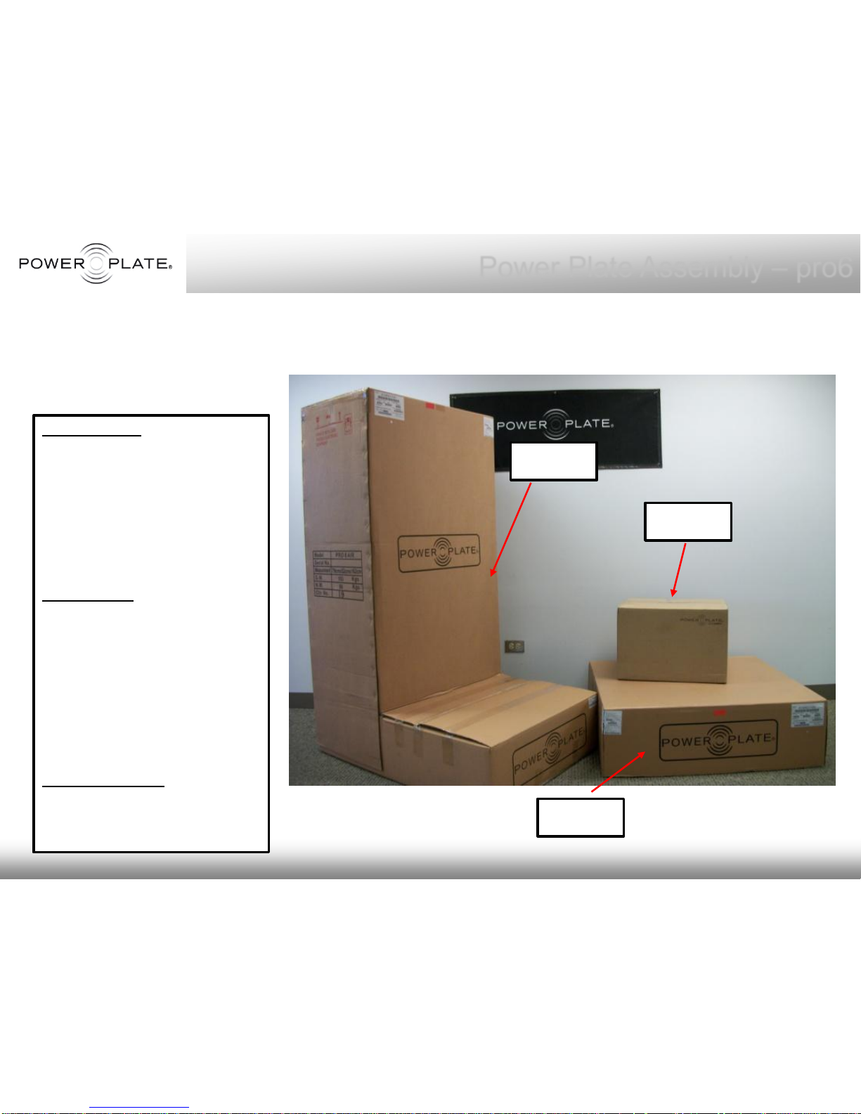
Platform Box:
• 1 Platform Assembly
• 2 Hand Straps
• 1 Black Platform Mat
• 4 Temporary Guide Bolts
• 4 Securing Bolts
• Dust Cover
Column Box:
• 1 Column Assembly
• 1 Power Cord
• User Manual
• Assembly Manual
• Poster
• Dust Cover
• Spare Fuses
proMOTION Box:
• 2 proMOTION Devices +
Mounting Brackets, Hex
Key & Hardware
Platform Assembly
Power Plate Assembly – pro6
Unpacking
The
pro6
is shipped in 3
boxes. Remove all parts from
shipping boxes and verify
that the following parts were
included in your shipment:
Column
Box
Platform
Box
proMOTION
Box
Page 4

© Copyright 2010 Power Plate International
Column
Assembly
Platform
Assembly
Power Plate Assembly – pro6
proMOTION
x (2)
Page 5

© Copyright 2010 Power Plate International
Looking at the Platform assembly
upside-down, notice the 4 “Air
Bellows" in each corner.
Temporary Guiding bolts need to be
inserted into each Air Bellow. The
Temporary Guide bolt screws into the
threaded opening on top of the Air
Bellow, these bolts will “guide” the
platform into place when mounting
the Platform to the Column, and line
up the holes to attach the Securing
bolts.
Air Bellow (4)
Temporary Guide Bolts (4)
screw into Air Bellows first
Power Plate Assembly – pro6
Temporary
Guide Bolts
Securing
Bolts
Page 6
© Copyright 2010 Power Plate International
Column Assembly
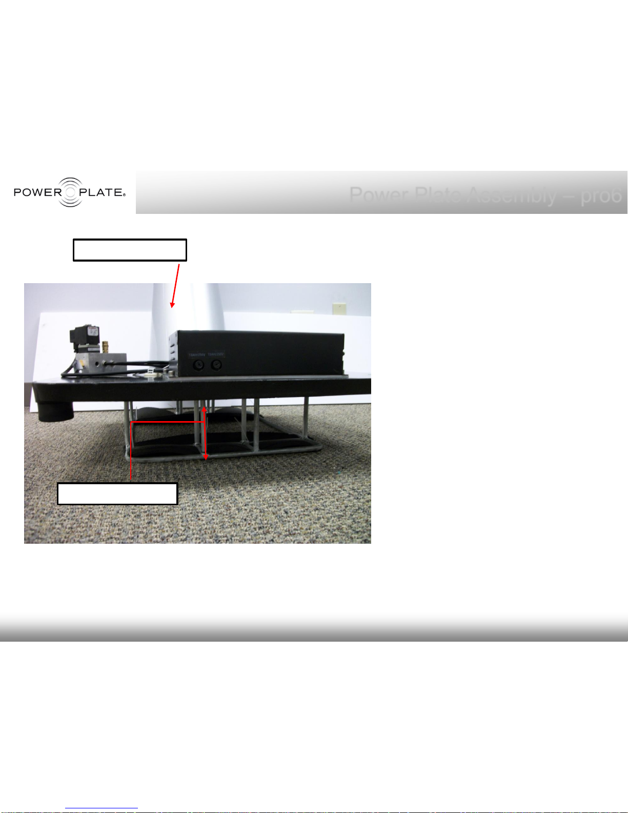
The Column assembly MUST be
raised off the floor in order to
assemble. Once the Column
assembly is set atop risers, (a
metal stand is used in photo) this
will provide a 6 – 8 inch clearance
from the iron base of the Column
assembly to the floor.
This clearance allows space for
the Securing Bolts to be set in
place after the Platform is
mounted on top.
7- 8 Inch Clearance
Power Plate Assembly – pro6
Page 7
© Copyright 2010 Power Plate International
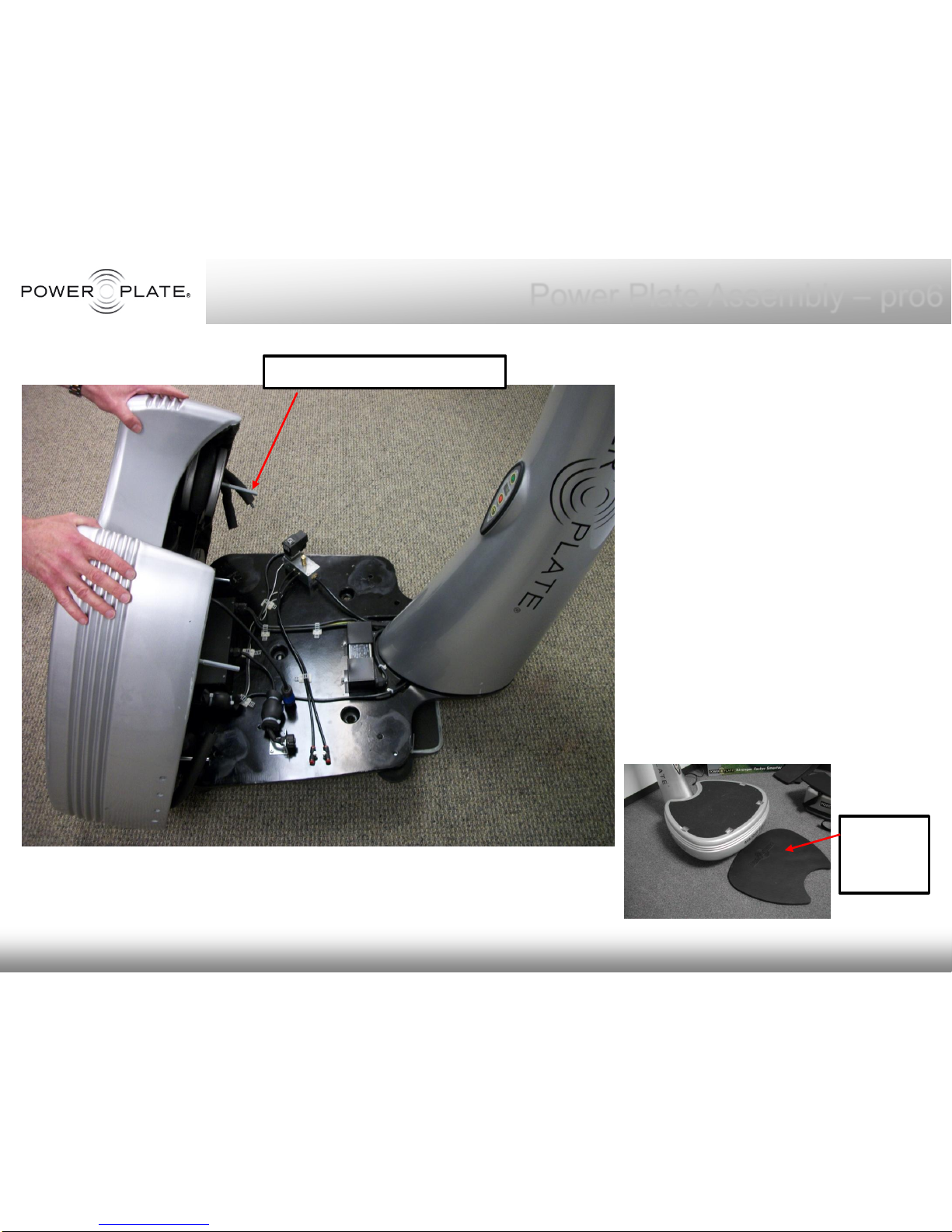
Platform assembly
should be positioned in
front of Column
assembly.
Please note, if not
installing on carpeted or
a protected surface,
please use the Black
Foam Platform Mat to
protect the Platform from
getting scratched from
the floor.
Black
Foam
Mat
Power Plate Assembly – pro6
Temporary Guide Bolts (4)
Page 8
© Copyright 2010 Power Plate International
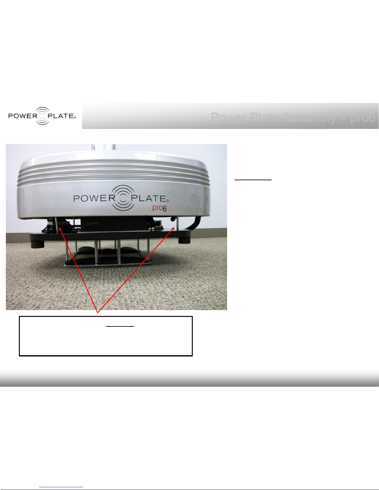
Gently lower the Platform onto the
iron base of the Column, making
sure the Temporary Guide Bolts
“DO NOT” go through their
appropriate holes, for now, but rest
on top of the iron base as shown in
photo.
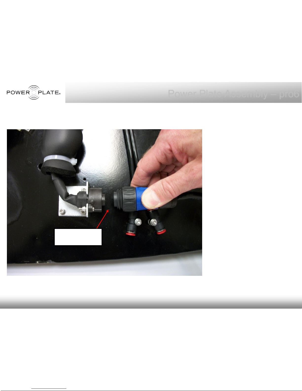
This will allow clearance for
connecting the Black Motor Cable
(from the motors on the platform),
into its connector which is secured
on a bracket on the iron base of
the Column.
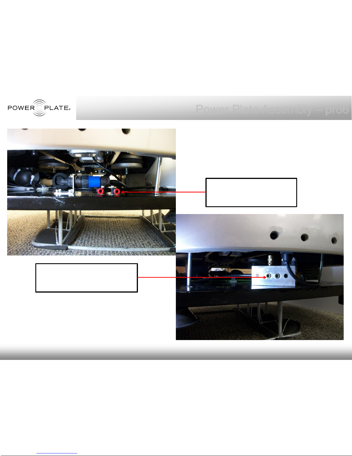
You must also connect the Air
Hoses to the appropriate Valve
connector from each Air Bellow at
this stage. To attach, simply push
Air Hose into Valve Connector, hose
will lock into place.
Temporary Guide Bolts DO NOT drop through
Holes on the Iron Base – set slightly aside and
rest on iron base surface for Motor Cable
And Air Hose attachments.
Power Plate Assembly – pro6
Page 9
© Copyright 2010 Power Plate International
Column
Assembly
Close up of Motor Cable
and its connector on the
iron base of the Column.
Connector will only secure
one way, a notch is
located on end of cable
that must line up the
notch indent on connector.
Motor Cable MUST BE
attached before Platform
is lowered completely onto
the iron base.
Power Plate Assembly – pro6
Attach Motor
Cable
Page 10
© Copyright 2010 Power Plate International
Power Plate Assembly – pro6
Attach 2 Air Hoses to Red
connectors on one side
of iron base
Air Hose Connections (4). Air Hoses
MUST BE attached before Platform is
lowered completely onto the iron base.
Attach 2 Air Hoses
to Manifold connectors on
one side of iron base
To attach Air Hoses, simply push into
connector fully. To remove the Air
Hoses, simply push in the “O” connector
while at the same time gently pulling the
Air Hose out.
Page 11
© Copyright 2010 Power Plate International
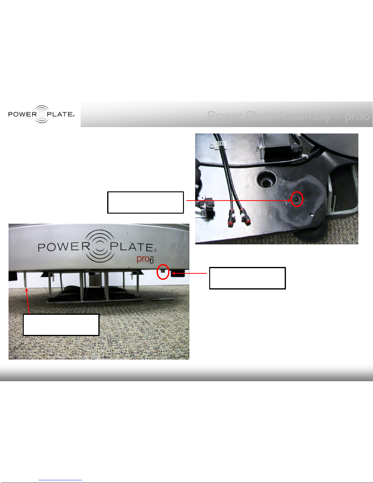
Now gently lower the Platform, guiding
the Temporary Guide bolts through the
bolt holes located on the iron base
Power Plate Assembly – pro6
Bolt holes on iron
base (4)
Once the Platform has been lowered,
remove the Temporary Guide bolts
and Insert the Securing bolts.
Insert Securing
bolts (4)
Remove Temporary
Guide bolts (4)
Page 12
© Copyright 2010 Power Plate International
Power Plate Assembly – pro6
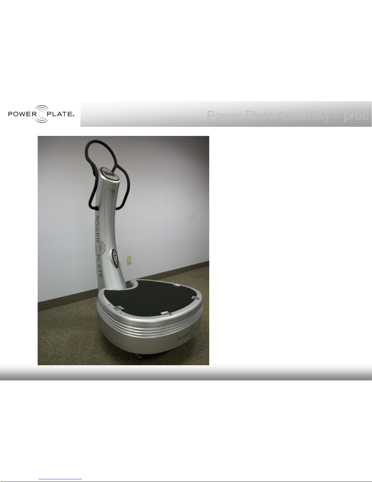
Once the 4 Securing bolts are in
place and hand tightened with
force, gently remove the assembly
riser which was used to raise the
Column assembly.
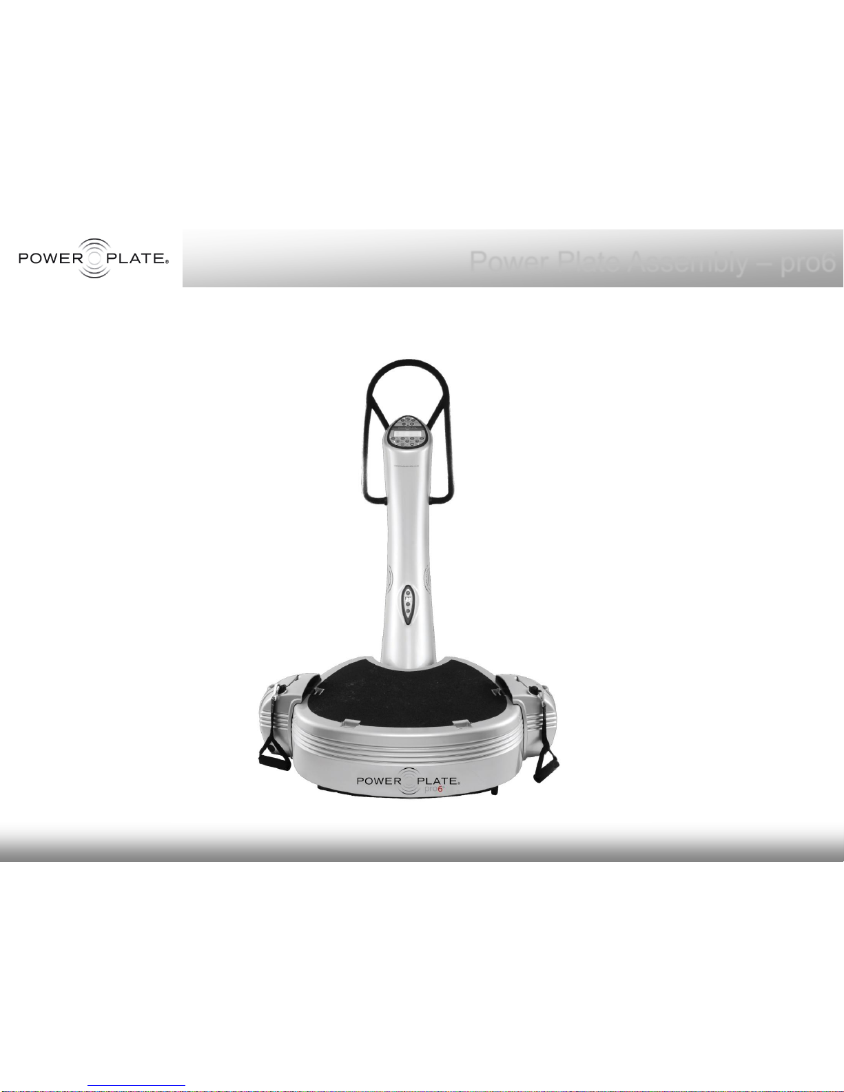
See photo of assembled pro6.
The pro6 Power Plate includes 2
proMOTION devices. After Column
& Platform are assembled and
secured together, the proMOTION
devices must be mounted to each
side of the Platform.
See following pages for
proMOTION mounting instructions
Page 13
© Copyright 2010 Power Plate International
Power Plate Assembly – pro6
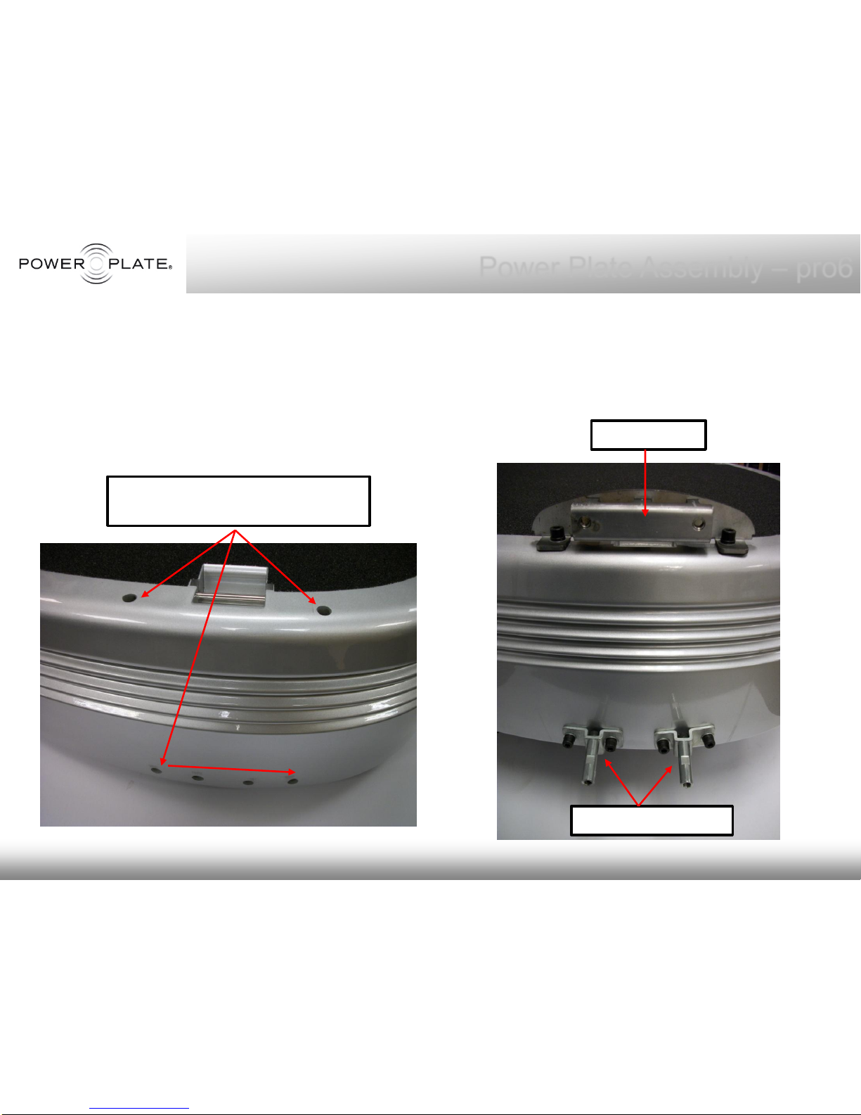
Secure the proMOTION Top and Bottom
Brackets to each side of the Platform
assembly.
proMOTION Mounting Instructions
Bolt holes on Platform for
proMOTION bracket mounting
Top Bracket
Bottom Brackets
Page 14
© Copyright 2010 Power Plate International
Power Plate Assembly – pro6
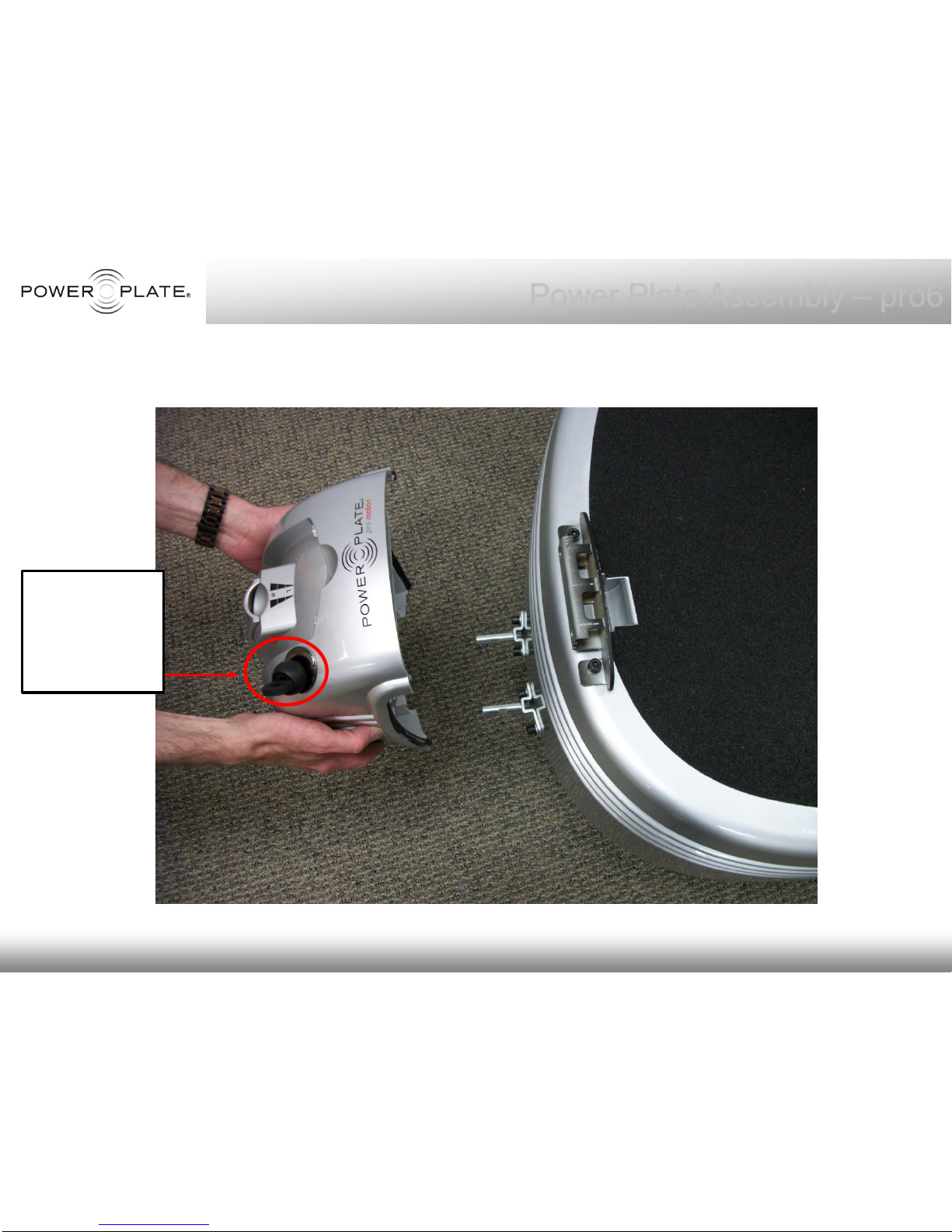
Place the proMOTION housing securely onto the mounting brackets (left and right.)
Please note
the cable
position in
regards to
the Platform
Page 15
© Copyright 2010 Power Plate International
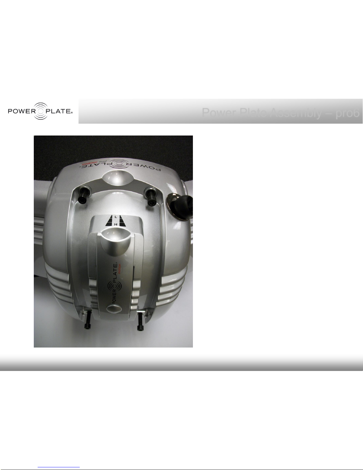
Place the bolts, apply Loctite 243
and tighten with a torque wrench
at 25Nm. (do this for Right and
Left proMOTION.)
Once proMOTION devices are
bolted on both Right and Left
sides of the pro6 platform, test the
devices by pulling out the cables
at least 2 times each.
Please see step by step Mounting
Diagram for proMOTION on the
next page.
Power Plate Assembly – pro6
Page 16
© Copyright 2010 Power Plate International
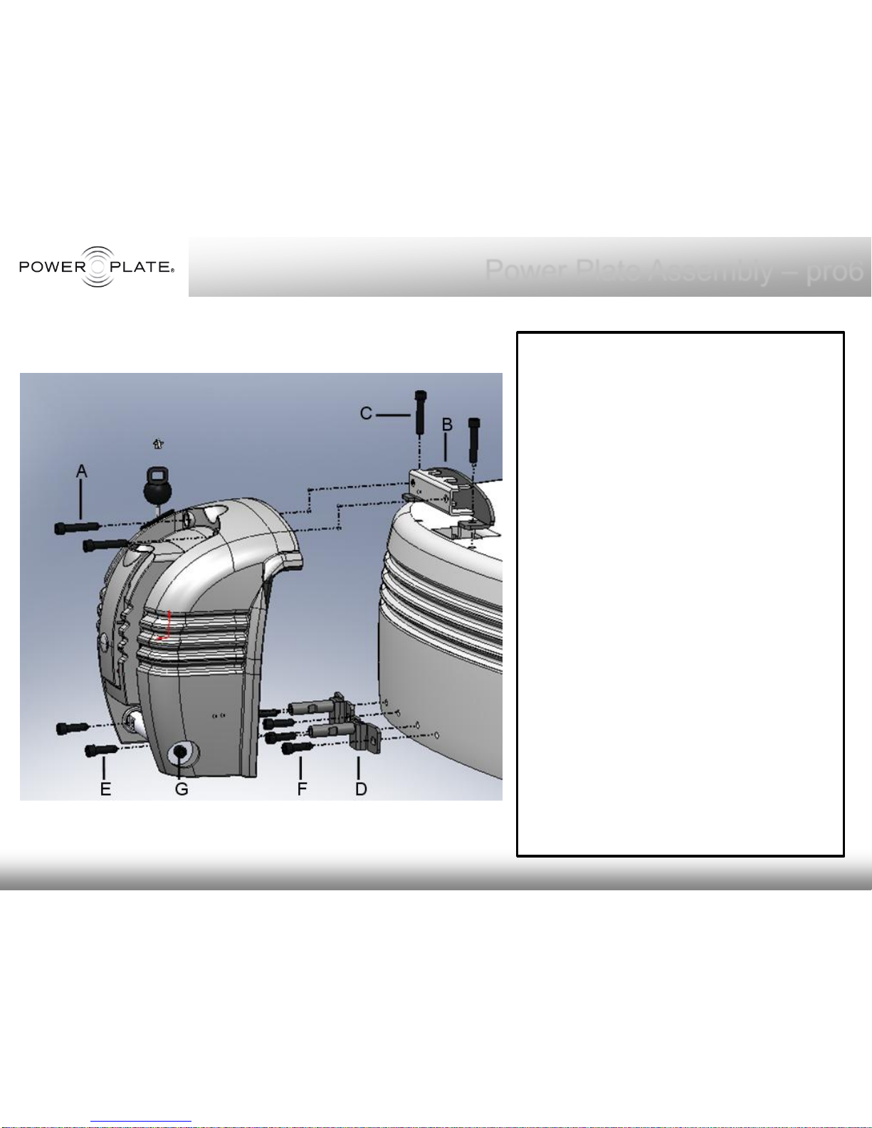
1. Remove the two M8 screws (A) and slide out
the top bracket (B).
2. Mount the top bracket (B) on the Powerplate
base with two M8 screws (C). Apply Loctite
243 on the screws before tightening them at
25Nm.
3. Take out the two lower brackets (D) by
removing two M8 screws (E).
4. Mount the two lower brackets (D) on the
Powerplate base with four M8 screws (F).
Apply Loctite 243 before tightening them at
25Nm.Make sure left and right is not swapped
and make sure the bracket is mount as on
above image and not upside down (round
metal bar should be on the top side)
5. Make sure the M8 screws (G) on left and right
side of the proMotionare loose, but do not
take them out.
6. Slide the promotion on the top bracket (B), and
push it strongly against the Powerplate.
7. Connect the promotion to the lower brackets
(D) by screwing in the two M8 screws (E)
loosely, apply Loctite 243 on them, but do not
tighten them yet!
8. Screw in two M8 screws with Loctite 243 on
the top (A) to fix the promotion on the top
bracket (B). Tighten them at 25Nm.
9. Tighten two M8 screws (E) for the lower
brackets at 25Nm.
10. Take out the two M8 screws (G) on the left and
right side of the promotion, apply Loctite 243
and tighten them at 25Nm.
Steps to follow for both left and right side
proMOTION Mounting Diagram
Power Plate Assembly – pro6
Page 17
© Copyright 2010 Power Plate International
Fully assembled pro6 Power Plate
Power Plate Assembly – pro6
Page 18
© Copyright 2010 Power Plate International
Testing - Start A Program
Power Plate Assembly – pro6
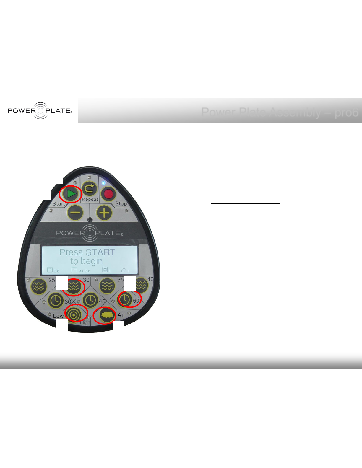
After the pro6 Power Plate is
assembled, please test the machine
by running through the various
programs for no less than 2 minutes.
To Start a Program:
1.Push Start
2.30 HZ
3.60 Seconds
4.Low Amplitude
5.Air 1
6.Push Start again
Please test all Frequencies, 25-40.
Also test both High/Low Amplitude
and all Air settings, 1,2 & 3.
1
2
3
4
5
6
Page 19
© Copyright 2010 Power Plate International
Power Plate Assembly – pro6
Contact and Support
If you have any questions, please visit our website, www.powerplate.com.
Select your country for local contact details.
Warranty / Product Registration:
To register your Power Plate® machine please visit us online at
www.powerplate.com. Copies of this manual and any other paperwork
may be obtained by contacting Power Plate through the “Contact Us”
page online or by writing to Power Plate:
Power Plate International Ltd
9A Utopia Village, 7 Chalcot Road
London NW1 8LH United Kingdom
T | +44207 586 7200
F | +44207 4837660
[email protected]
Power Plate North America Inc
17900 Von Karman, Suite 125
Irvine, CA 92614, USA
T | +1 949 8631737
F | +1 949 8631216
[email protected]
877 87 PLATE
www.powerplate.com
Page 20

© Copyright 2010 Power Plate International
 Loading...