

Page 1
PPoow
weerr PPllaattee ®
Pro 5
SSEMBLY INSTRUCTIONS
A
Page 2

4-6
INCH CLEARANCE
Assembly and Setup
Unpacking
The Pro 5 Power Plate is shipped in 2 boxes. Remove all parts from both shipping boxes and
verify that the following parts were included in your shipment:
Platform Box:
Description Qty.
Platform Assembly 1
Power Cord 1
Rubber Feet 4
Hand Strap 2
Foam Platform Mat 1
White Foam Diamond Inserts 4
Column Box:
Description Qty.
Column Assembly 1
Assembly
No tools are required for assembly.
1. Place the steel base of the
column on some type of
risers, such as two 4x4’s,
styrofoam or rubber blocks to
give you some clearance for
attaching the rubber feet
later.
Step 1
Page 3

2. Insert the White Foam Diamond Inserts into the vibration rubbers in the
platform as shown. If not in a carpeted area, please make sure the
platform is protected while on its top surface.
Step 2
3. Gently lower the vibrating platform on top of the steel plate of the column
in the position where the Black Motor cable on the vibrating platform is in
position to attach to its connection on the steel plate of the vertical column,
and the yellow ground wire is also in position to attach to the ground
connection on
the steel plate.
• Tip- The
vibrating
plate will
curve
around the
base of
the
column
Page 4
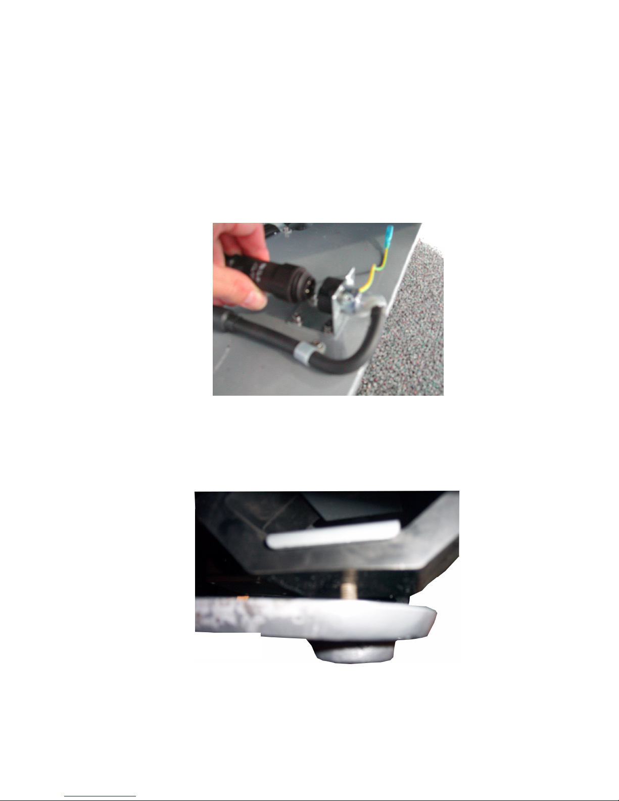
4. Reach under the vibrating plate and secure Black Motor Cable to its
connector. The black cord will only go in ONE way then screw to fix
permanent seal. Then attach yellow/green ground wire after.
• Tip- Once the vibrating platform is in position over the steel plate,
for convenience, have another person slightly lift the vibrating plate,
while another makes the power and ground connections.
Step 4
5. After connecting both cables, you need to “drop” the screws down
(attached to platform) through the hole in the steel base.
Step 5
Page 5
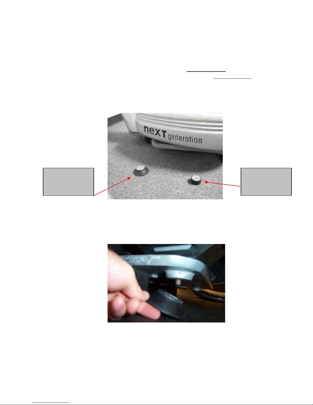
6. Finally, attach the 4 feet. *Please note – the 2 Rubber Post shaped feet
(pic. 1) are attached to the front of the plate, while the 2 Suction Cup
shaped feet (pic. 2) are attached to the back of the platform. The feet are
threaded; simply screw on the rubber feet tightly to the platform bolt.
Pic. 2 – Rubber
Suction Cup
-shaped feet go on
back of the machine
Step 6
Pic. 1 - Rubber Post
- shaped feet go on
the front of the
machine
Page 6
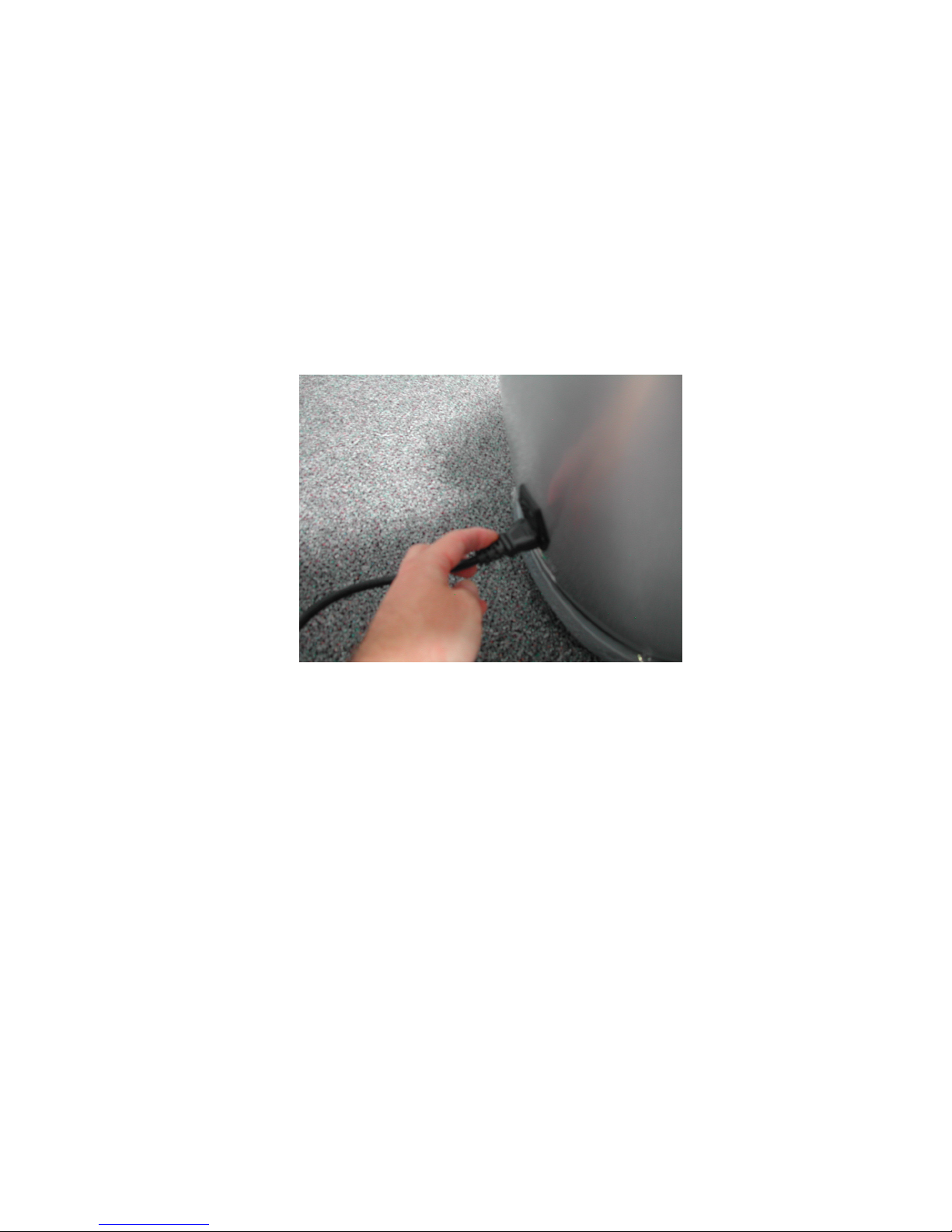
7. You are done. Connect the black power cord to the back of the machine
and wall. The On / Off Switch is located on the lower back of column, turn
to I for “on” and O for “off”.
• Tip- Please secure Power Cord tightly to the back of the column, as
to not come loose.
Step 7
Page 7
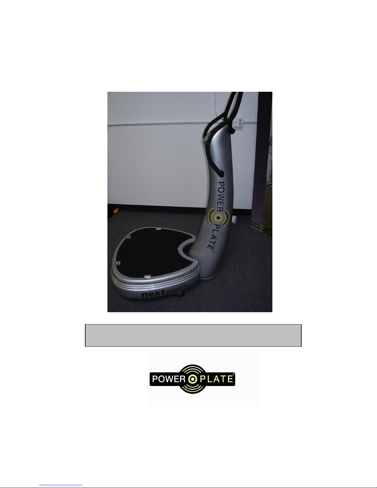
Completed Assembly
For any further assembly or installation questions, please
call Power Plate North America, Inc. at 847-509-6000.
 Loading...