

PowerPal MHG-T2 User Manual
Use and Care
Instructions
for your new
T2 Turgo
Micro-hydroelectric Generator
Models: MHG-T2
Asian Phoenix Resources Ltd., Canada
PowerPal™ T2 Turgo 1
READ THIS FIRST
p
p
This manual contains important information concerning your new PowerPal T2 Turgo
micro-hydroelectric generator. It covers Model MHG-T2. You should read this
manual carefully before installing PowerPal or allow a trained technician from your
local PowerPal Service Center to install it for you.
Your PowerPal generator is designed to be simple to operate and easy to maintain. If
used in accordance with these instructions your PowerPal will give you many years of
service. PowerPal is also designed with safety in mind, but any electric device can be
dangerous if not used correctly. At several points in this manual, instructions
requiring special attention that must be followed are shown as:
Warning symbol - beware of hazards or unsafe practices that may cause
injury or death.
Caution symbol – beware of hazards or unsafe practices that may damage the
roduct.
SAFETY FIRST
While electricity improves your life, it can also be dangerous if simple
• Never allow electrical contacts to become wet. Beware of electrocution.
• Never attempt to cut electrical wires or open appliances for repair if the generator
• Inform children of the dangers of electrocution. Never allow them to play with
• Keep fingers away from the moving turbine runner. If partly blocked with debris,
• If you have any questions about safety, please ask your PowerPal Service Center.
• Product must be earth bonded (grounded).
OPERATING CAUTIONS
• Under conditions of higher water heads than given for each model in this manual,
• Do not forget to grease the bearings at the recommended times. Failure to do this
•
recautions are not followed:
is working. Unplug the main cable first.
electrical connections.
stop the water flow before cleaning.
Your PowerPal generator is designed for simple operation and low
maintenance. However, the following operating cautions must be followed to
ensure a long life for PowerPal:
PowerPal is able to generate higher power outputs than rated. This can also occur
if the intake pipe diameter exceeds the recommended diameter. If maximum
power consumption listed in this manual is exceeded then the PowerPal generator
may be irrepairably damaged and require total rewiring. See the section on
‘Technical Specifications’.
will result in excessive wear on the bearings and shorten their life.
Always ensure that the Electronic Load Controller is set at approximately 220V.
Otherwise, the life of lights and appliances may be reduced.
PowerPal™ T2 Turgo 2

POWERPAL COMPONENTS
Inside your PowerPal box you will find:
• 1 x generator-turbine assembly
• 1 x penstock adaptor flange, internal diameter 110mm
• 1 x rubber gasket
• 4 x M10 foundation nuts and bolts
• 1 x control panel including electronic load controller
• 1 x ballast load
• 1 x Guarantee Card
• 1 x this instruction manual.
Please advise immediately if any parts are missing. Complete your Guarantee Card
and have it signed by your PowerPal dealer.
The PowerPal system consists of two major components – a hydroelectric generator
and an electronic load controller. Other components are necessary and these can be
purchased locally. The penstock (intake pipe) should be made from either steel or
schedule 40 PVC. Your PowerPal dealer can advise you about this.
Therefore, other parts which are not included in the box but which are required to
make PowerPal work are:
• a length of steel or PVC pipe with internal diameter 110mm. Pipe length will
affect your power output (see page 5).
• electrical wire from generator to house. See the section on ‘Technical
Specifications’ for the correct wire size.
• household wiring.
These are available from your dealer or local electrical store.
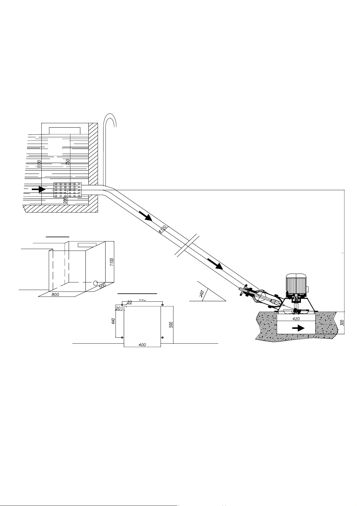
SYSTEM DIAGRAM
The following diagram shows how the non-electrical components fit together. Further
reading of this manual will provide the necessary explanations. The components are:
PowerPal™ T2 Turgo 3
E
D
A
Forebay
B
A. Forebay, or water
tank
B. Atmospheric vent
C. Penstock, or intake
pipe
D. Spear valve
E. Turbine
C
Turbine stand
PowerPal™ T2 Turgo 4
SELECTING A SITE
m
D
PowerPal is designed for use in a wide range of locations. There are two critical
factors that influence power output – head and flow. Head is the vertical distance
between the turbine and the water source (forebay), measured in meters. Flow is the
amount of water that passes through the turbine at any instant, measured in litres per
second (l/sec).
See Page 17 for detailed head, flow rate and output data for the three T2 models.
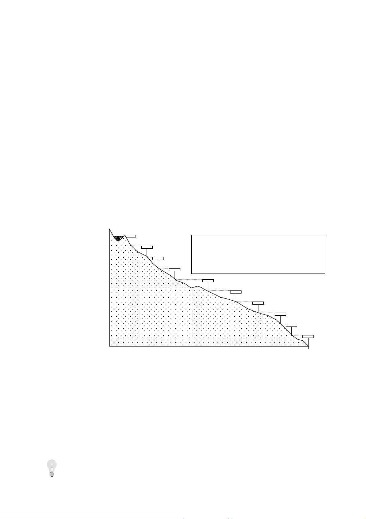
Measuring Gross Head
The gross head is the vertical height from where the water flow enters the penstock
down to the level of the turbine. It is shown in the System Diagram. To measure this,
use a tape measure and a clinometer or spirit level etc. A less accurate but useful
alternative is to make your own level from a transparent tube half-filled with water.
Attach this to the top of a 1m long stick and then point this horizontally at a point
further up the slope as though it were a spirit level. By going to that point and
repeating the process the total gross head can be measured – see the drawing below.
10m
9
8
7
6
5
4
3
2
1
0
Measuring Gross Head:
Walk up the slope from where you wish to place
the turbine to where the water source is. Or, do
the reverse: walk down the slope from the wa
source to locate the best site for the turbine.
Another method is to use an accurate pressure gauge and a length of hose. Run a
water-filled hose from the forebay to the turbine site and attach the pressure gauge to
the bottom end. The pressure gauge shows 1.422 psi / meter of head e.g. 11.4 psi for a
head of 8m to 24.2 psi for a head of 17m.
This head should be between 15 and 21 meters for the MHG-T2 model. If it is smaller
then the power output will be reduced. If it is larger then your power output will be
increased. While increased power output appears desirable, if the head is too large
then the rotor will turn too fast and reduce the life of the bearings unless the spear
valve is used to reduce flow.
o not attempt to exceed the recommended head height.
ter
PowerPal™ T2 Turgo 5
Measuring Flow
The best way to measure the water flow is to take a piece of pipe the same diameter as
the penstock, insert it in the stream or dam where the flow is expected to come from,
and measure the flow from there.
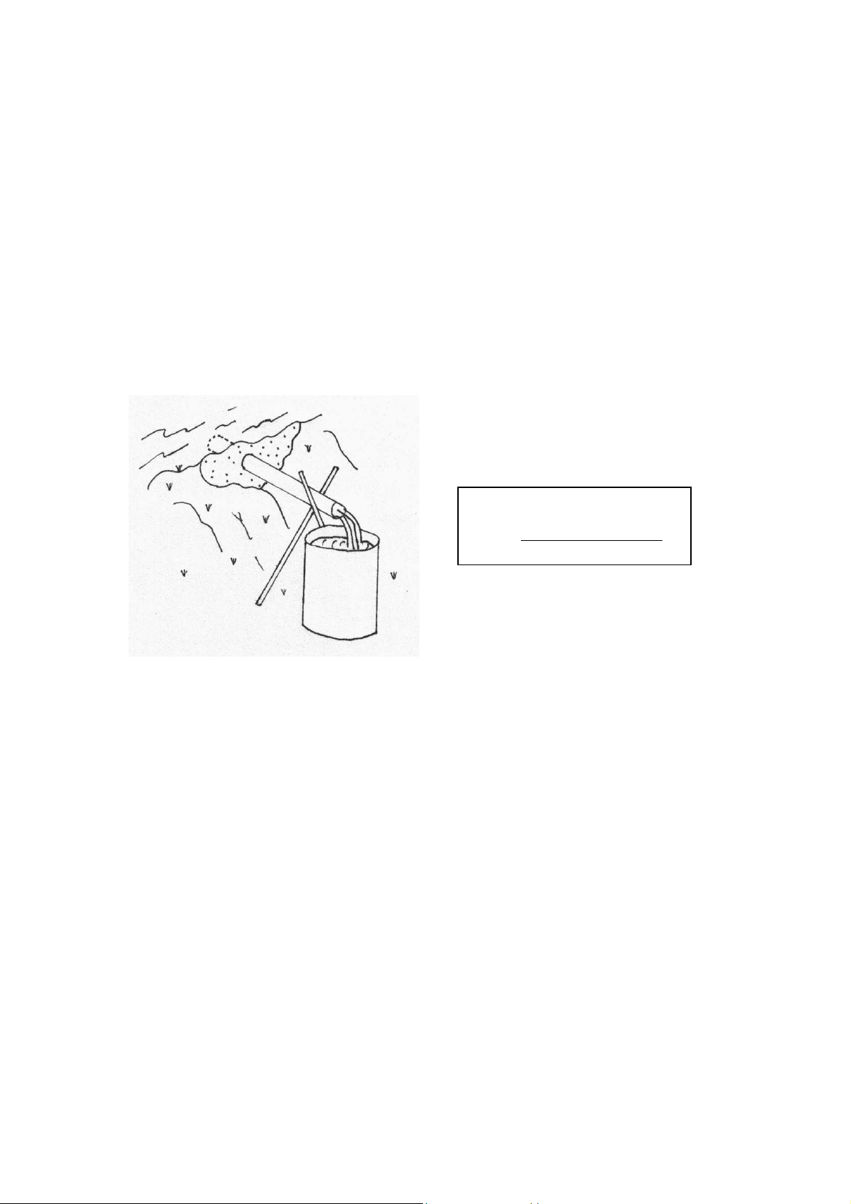
In the diagram below, a short length of pipe (less than 1 meter) is buried into the side
of a small ‘dam’ using mud or improvised sandbags. The top end of the pipe is
completely submerged and part of the normal stream flow is diverted through the
pipe. When this is flowing smoothly, a bucket of known volume is quickly placed to
collect this flow and the time it takes to fill the bucket is recorded. The ideal bucket
size would be 100 or 200 litres (half or a whole empty oil drum), but smaller buckets
will work. Divide the volume of the bucket (in litres) by the time it takes to fill the
bucket (in seconds) to get the approximate flow rate in litres per second.
Measuring Flow:
Flow = volume of bucket (litres)
time to fill bucket (seconds)
SITE PREPARATION
Once the correct head and flow have been located then the length and position of the
penstock can be determined. While vertical head is important, the horizontal slope and
penstock length may vary although penstock inclination should be >60°.
The penstock should be made of PVC or steel with internal diameter of 110mm and
thickness of at least 3mm. A larger diameter pipe can be used however this is
generally more costly. A gate valve is a good idea and may be installed at the highpressure end of the penstock for closing whenever servicing the turbine.
A good way to reduce penstock length is shown in the following diagram.
PowerPal™ T2 Turgo 6
 Loading...