

Product Specifications
NV Series: 4 - 6W DC/DC Converters Oct 2001
9-36V, 18-36V, 36 -72V & 16 -75V Inputs
3.3V, 5.0V, 12V, 15V, ±5.0V, ±12V, ±15V & ±24V Outputs
18-Oct-01 Rev 1.0 Page 1 of 11
www.power-one.com
Applications
• Distributed power architectures
• Telecommunications equipment
• LAN/WAN applications
• Data processing
Features
• Single board design
• 8.5 mm height profile
• Excellent co-planarity
• Input/output isolation: 1500 Vdc
• Low conduc ted and radiated EMI
• Output overcurrent protection
• Parallel and series connection providing
flexible output voltages and power
• Full rated output power at 71ºC with
convection cooling
• Operating temperature to 110ºC
• UL, CSA and EN/IEC60950 (3rd ed.) approved
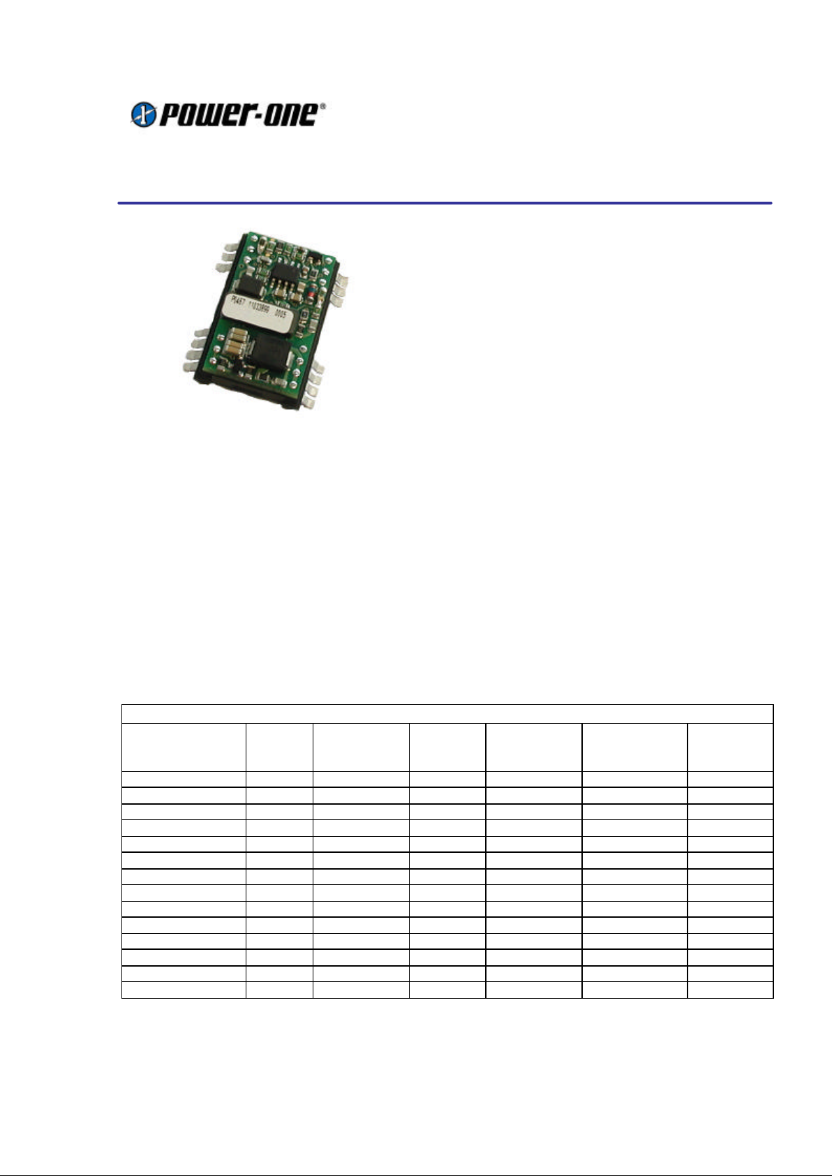
Description
The NV series of converters are low profile, single and dual outputs, DC/DC converters intended for SMT
placement and reflow soldering. The product provides on-board conversion of a wide range of standard
telecom and datacom input voltages to isolated low output voltages. Proprietary patented manufacturing
process with full process automation ensures optimal product quality in an extremely small footprint.
Selection Chart – Single output
Model Input
voltage,
Vdc
Input
current,
max, Adc
Output
voltage,
Vdc (Vo)
Output rated
current,
Adc (Io.Max)
Output ripple
and noise,
mVp-p
Efficiency,
%
NVS01YG-M6 18-36 0.27 5.0 1.0 50 82
NVS0.5YH-M6 18-36 0.33 12 0.5 95 83
NVS0.4YJ-M6 18-36 0.33 15 0.4 120 84
NVS01ZE-M6 36-75 0.17 5.0 1.0 50 82
NVS0.5ZH-M6 36-75 0.17 12 0.5 95 82
NVS0.4ZJ-M6 36-75 0.17 15 0.4 120 84
NVS0.9CE-M6 9-36 0.45 3.3 0.9 50 79
NVS0.7CG-M6 9-36 0.55 5.0 0.7 50 81
NVS0.3CH-M6 9-36 0.65 12 0.34 95 82
NVS0.3CJ-M6 9-36 0.65 15 0.28 120 82
NVS0.9EE-M6 18-75 0.33 3.3 0.9 50 80
NVS0.7EG-M6 18-75 0.33 5.0 0.7 50 81
NVS0.3EH-M6 18-75 0.33 12 0.34 95 82
NVS0.3EJ-M6 18-75 0.33 15 0.28 120 82
Continued next page
Product Specifications
NV Series: 4 - 6W DC/DC Converters Oct 2001
9-36V, 18-36V, 36 -72V & 16 -75V Inputs
3.3V, 5.0V, 12V, 15V, ±5.0V, ±12V, ±15V & ±24V Outputs
18-Oct-01 Rev 1.0 Page 2 of 11
www.power-one.com
Continued from previous page
Selection Chart – Dual Outputs
Model Input
voltage,
Vdc
Input
current,
max, Adc
Output
voltage,
Vdc (Vo)
Output rated
current,
Adc (Io.Max)
Output ripple
and noise,
mVp-p
Efficiency,
%
NVD01YGG-M6 18-36 0.27 ±5.0 ±0.50 60 82
NVD0.5YHH- M6 18-36 0.33 ±12 ±0.25 100 83
NVD0.3YJJ-M6 18-36 0.33 ±15 ±0.14 120 84
NVD01ZGG-M6 36-75 0.17 ±5.0 ±0.50 60 82
NVD0.5ZHH-M6 36-75 0.17 ±12 ±0.25 100 83
NVD0.3ZJJ-M6 36-75 0.17 ±15 ±0.14 120 84
NVD0.7CGG- M6 9-36 0.65 ±5.0 ±0.35 50 81
NVD0.3CHH- M6 9-36 0.65 ±12 ±0.17 95 82
NVD0.3CJJ-M6 9-36 0.65 ±15 ±0.14 120 82
NVD0.1CKK- M6 9-36 0.65 ±24 ±0.08 190 83
NVD0.7EGG- M6 18-75 0.33 ±5.0 ±0.35 50 81
NVD0.3EHH- M6 18-75 0.33 ±12 ±0.17 95 82
NVD0.3EJJ-M6 18-75 0.33 ±15 ±0.14 120 82
NVD0.1E KK-M6 18-75 0.33 ±24 ±0.08 190 83
Absolute Maximum Ratings
Stresses in excess of the absolute maximum ratings may cause performance degradation, adversely affect
long term reliability and cause permanent damage to the converter. Specifications apply over specified input
voltage, output load and temperature range, unless otherwise noted.
Parameter Conditions/Description Min Max Units
Operating CaseTemp. (Tc) At 100% load -40 110
°C
Storage Temperature (Ts) -55 120
°C
Environmental and Mechanical Specifications
Parameter Conditions/Description Min Nom Max Units
Shock IEC68- 2-27 100 g
Sinusoidal Vibration IEC68- 2-6 10 g
Weight 0.4/12 oz/g
Water Washing Standard process Yes N/A
MTBF Per Bellcore TR-NWT-000332 3,000 kHrs
Isolation Specifications
Parameter Conditions/Description Min Nom Max Units
Insulation Safety Rating Vin = Vin.Min – Vin.Max Operational N/A
Isolation Voltage (Vps) 1,500 Vdc
Isolation Resistance (Rps) 10 MOhm
Isolation Capacitance (Cps) 1,100 pF
Product Specifications
NV Series: 4 - 6W DC/DC Converters Oct 2001
9-36V, 18-36V, 36 -72V & 16 -75V Inputs
3.3V, 5.0V, 12V, 15V, ±5.0V, ±12V, ±15V & ±24V Outputs
18-Oct-01 Rev 1.0 Page 3 of 11
www.power-one.com
Input Specifications (9-36V)
Parameter Conditions/Description Min Nom Max Units
Input voltage (Vin)
Transient Input Voltage (Vint)
Continuous
Transient, 100ms
9 36
40
Vdc
Vdc
Input Current when Shutdown Vin.Nom, Iout = 0A 10 20 mAdc
Turn-On Input Voltage 9- 36 Vin Ramping Up, Io.Max 8 8.5 9 Vdc
Turn-Off Input Voltage 9- 36 Vin Ramping Down, Io.Max 8 8.5 9 Vdc
Turn-On Time To Output Regulation Band
Rise Time
250
10
500 ms
ms
Input Reflected Ripple Current Vin.Max, Io.Max 30 mAp-p
Input Capacitance 0.6
µF
Switching Frequency Vin.Nom, Io.Max 250 kHz
Temperature Coefficient 0.02
%Vo/°C
Input Specifications ( 18-36V)
Parameter
Conditions/Description Min Nom Max Units
Input voltage (Vin)
Transient Input Voltage (Vint)
Continuous
Transient, 100ms
18 36
40
Vdc
Vdc
Input Current when Shutdown Vin.Nom, Iout = 0A 10 20 mAdc
Turn-On Input Voltage 9- 36 Vin Ramping Up, Io.Max 16 17 18 Vdc
Turn-Off Input Voltage 9- 36 Vin Ramping Down, Io.Max 16 17 18 Vdc
Turn-On Time To Output Regulation Band
Rise Time
250
10
500 ms
ms
Input Reflected Ripple Current Vin.Max, Io.Max 30 mAp-p
Input Capacitance 0.6
µF
Input Specifications (16-75V)
Parameter Conditions/Description Min Nom Max Units
Input voltage (Vin)
Transient Input Voltage (Vint)
Continuous
Transient, 100ms
16 75
100
Vdc
Vdc
Input Current when Shutdown Vin.Nom, Iout = 0A 8 10 mAdc
Turn-On Input Voltage 9- 36 Vin Ramping Up, Io.Max 14 15 16 Vdc
Turn-Off Input Voltage 9- 36 Vin Ramping Down, Io.Max 14 15 16 Vdc
Turn-On Time To Output Regulation Band
Rise Time
250
10
500 ms
ms
Input Reflected Ripple Current Vin.Max, Io.Max 30 mAp-p
Input Capacitance 0.3
µF
Input Specifications (36-75V)
Parameter Conditions/Description Min Nom Max Units
Input voltage (Vin)
Transient Input Voltage (Vint)
Continuous
Transient, 100ms
36 75
100
Vdc
Vdc
Input Current when Shutdown Vin.Nom, Iout = 0A 8 10 mAdc
Turn-On Input Voltage 9- 36 Vin Ramping Up, Io.Max 32 34 36 Vdc
Turn-Off Input Voltage 9- 36 Vin Ramping Down, Io.Max 32 34 36 Vdc
Turn-On Time To Output Regulation Band
Rise Time
250
10
500 ms
ms
Input Reflected Ripple Current Vin.Max, Io.Max 30 mAp-p
Input Capacitance 0.3
µF
Product Specifications
NV Series: 4 - 6W DC/DC Converters Oct 2001
9-36V, 18-36V, 36 -72V & 16 -75V Inputs
3.3V, 5.0V, 12V, 15V, ±5.0V, ±12V, ±15V & ±24V Outputs
18-Oct-01 Rev 1.0 Page 4 of 11
www.power-one.com
Output Specifications
All specifications apply over input voltage, output load and temperature range, unless otherwise noted.
All Models
Parameter Conditions/Description Min Nom Max Units
Output Voltage Accuracy Vin.Nom, 50% Io.Max ±1 %Vo
Line Regulation Vin.Min to Vin.Max, 50% Io.Max ±1 %Vo
Load Regulation Vin.Nom, Io.Min to Io.Max
3.3Vo
Other Output Voltages
±3.5
±3.0
%Vo
%Vo
Maximum Output Capacitance Total, for single and dual outputs
3.3Vo
5Vo, ±5Vo
12Vo, ±12Vo
15Vo, ±12Vo
±24Vo
680
680
150
100
45
µF
µF
µF
µF
µF
Dynamic Regulation
Peak Deviation
Settling Time
50- 100% Io.Max load step
change
to 1% error band
5.0
1.0
%Vo
ms
Output Voltage Ripple Vin.Min to Vin.Max, Io.Min to Io
Max, 20MHz Bandwidth
3.3Vo
5Vo, ±5Vo
12Vo, ±12Vo, ±24Vo
50
50
0.8
80
80
1
mVp-p
mVp-p
%Vo p-p
Output Current Limit Threshold Output Current Limit Threshold 120 200 %Io.Max
Switching Frequency Vin.Nom, Io.Max 250 KHz
Temperature Coefficient 0.02
%Vo/°C
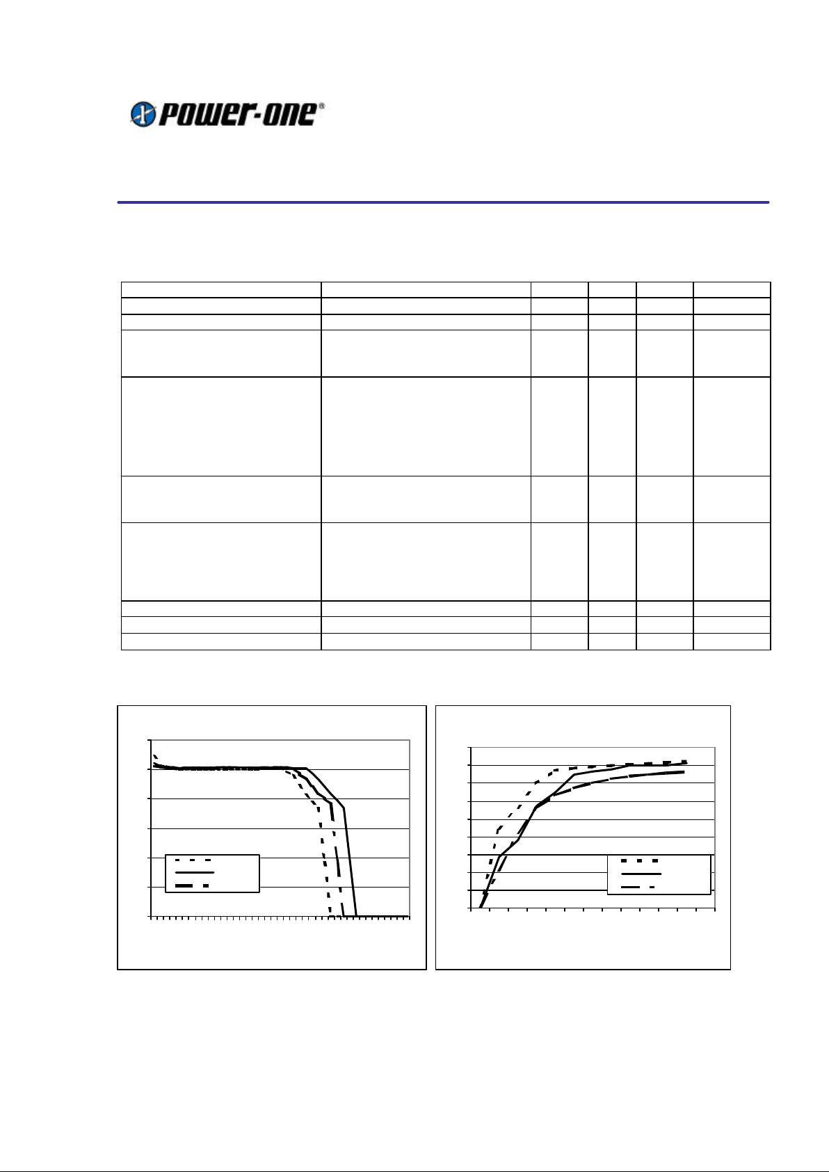
Typical characteristic curves for single 5V output type
Output Voltage Vs Load
0.00
1.00
2.00
3.00
4.00
5.00
6.00
0.00
0.18
0.36
0.54
0.72
0.90
1.08
1.26
1.44
1.62
1.80
1.98
2.16
2.34
Iout (A)
Vout (V)
Vin Min
Vin Nom
Vin Max
Efficiency Vs Load
0%
10%
20%
30%
40%
50%
60%
70%
80%
90%
0%
6%
12%
24%
36%
48%
60%
72%
84%
96%
108%
120%
Iout (A)
Efficiency
Vin Min
Vin Nom
Vin Max
25% 50% 75% 100%

Product Specifications
NV Series: 4 - 6W DC/DC Converters Oct 2001
9-36V, 18-36V, 36 -72V & 16 -75V Inputs
3.3V, 5.0V, 12V, 15V, ±5.0V, ±12V, ±15V & ±24V Outputs
18-Oct-01 Rev 1.0 Page 5 of 11
www.power-one.com
Temperature Derating Curves
The derating curves below give an indication of
the output power achievable with and without
forced air-cooling. However in the final application
the temperature rise of the converter is also
influenced by factors such as heat conduction
through the leads to the PCB, orientation, the
temperature of surrounding components and the
input voltage. To ensure the reliability of the
converter, care must be taken to guarantee that
the maximum case temperature is not exceeded
under any conditions. The measurement point for
case temperature is specified on the mechanical
drawing (Tc).
Temperature derating for 18-36V and 36- 75V
input voltage ranges :
The 9-36V and 18-75V input voltage versions of
this series feature a 4:1 input voltage range and
can achieve operation at full power at 85ºC
ambient temperature with only convection cooling.
Temperature derating for 9-36V and 18-75V input
voltage ranges :
Typical Application
This series of converters does not require any
external components for proper operation.
However, if the distribution of the input voltage to
the converter contains significant inductance, a
capacitor across the input terminals may be
required to stabilize the input voltage. A minimum
of 0.47µF, quality electrolytic / ceramic capacitor
is recommended for this purpose. For output
decoupling it is recommended to connect, directly
across the output pins, a 0.47µF ceramic
capacitor (for 3.3V and 5V outputs) or a 0.27µF
ceramic capacitor (for other outputs).
Care must be taken to ensure the maximum rated
output capacitance for the device is not exceed
when dimensioning decoupling capacitors in the
system as this could cause the unit to detect an
overload and enter a ‘hiccup’ mode of operation.
Output Power Vs Ambient Temp. & Airflow
0
20
40
60
80
100
120
0
10
20
30
40
50
60
70
80
90
100
110
Ambient Temp. (deg °C)
Output Power (%)
400LFM (2 m/s)
200LFM (1 m/s)
0 LFM
Output Power Vs Ambient Temp. & Airflow
0
20
40
60
80
100
120
0
15
25
35
45
55
65
75
85
95
105
110
Ambient Temp. (deg °C)
Output Power (%)
200LFM (1 m/s)
0 LFM

Product Specifications
NV Series: 4 - 6W DC/DC Converters Oct 2001
9-36V, 18-36V, 36 -72V & 16 -75V Inputs
3.3V, 5.0V, 12V, 15V, ±5.0V, ±12V, ±15V & ±24V Outputs
18-Oct-01 Rev 1.0 Page 6 of 11
www.power-one.com
Output Current Limiting
When the output is overloaded above the
maximum output current rating, the voltage will
start to reduce to maintain the output power to a
safe level. In a condition of high overload or
short-circuit where the output voltage is pulled
below approximately 30% of Vo.Nom, the unit will
enter a ‘Hiccup’ mode of operation. Under this
condition the unit will attempt to restart,
approximately every 100ms until the overload has
cleared.
Parallel Operation
Paralleling of two converters is possible by direct
connection of the output voltage terminal pins.
The load regulation characteristic is designed to
facilitate current sharing (typically ± 20%).
Series Operation
The outputs of two units may be connected in series to
achieve a higher system voltage.
Safety Considerations
These converters feature 1500 Volt DC isolation
from input to output. The input to output
resistance is greater than 10MOhm. These
converters are provided with Operational
Insulation between input and output circuits
according to EN60950 / UL1950 / CSA60950-00.
Nevertheless, if the system using the converter
needs to receive safety agency approval, certain
rules must be followed in the design of the
system. In particular, all of the creepage and
clearance requirements of the end-use safety
requirements must be observed. These
documents include UL60950, CSA60950-00 and
EN60950, although specific applications may
have additional requirements.
In order for the output of the converter to be
considered as SELV (Safety Extra Low Voltage)
or TNV-1, according to EN60950 / UL1950 /
CSA60950-00, one of the following requirements
must be met in the system design:
• The converter has no internal fuse. An
external fuse must be provided to protect the
system from catastrophic failure. The
recommended fuse values are shown below:
Input Voltage Range Recommended Fuse
36-75V F0.315A
18-36V F0.5A
9-36V F1.0A
18-75V F0.5A
• The user can select a lower rating fuse based
upon the inrush transient and the maximum
input current of the converter, which occurs at
the minimum input voltage. Both input traces
and the chassis ground trace (if applicable)
must be capable of conducting a current of 1.5
times the value of the fuse without opening.
The fuse must not be placed in the grounded
input line, if any.
• If the voltage source feeding the module is
SELV, the output of the converter is
considered SELV and may be grounded or
ungrounded.
• The circuitry of the converter may generate
transients, which exceed the input voltage.
Even if the input voltage is SELV (<60V) the
components on the primary side of the
converter may have to be considered as
hazardous. A safety interlock may be needed
to prevent the user from accessing the
converter while operational.

Product Specifications
NV Series: 4 - 6W DC/DC Converters Oct 2001
9-36V, 18-36V, 36 -72V & 16 -75V Inputs
3.3V, 5.0V, 12V, 15V, ±5.0V, ±12V, ±15V & ±24V Outputs
18-Oct-01 Rev 1.0 Page 7 of 11
www.power-one.com
EMC Specifications
Conducted Noise:
The converters meet the requirements of
EN55022, CISPR22 and FCC CFR title 47 part 15
Sub-part J - Conducted (conducted noise on the
input terminals) without any external components.
The results for this solution are displayed below.
To meet level B for the above standards it is
necessary to fit a 3.3µF ceramic capacitor across
the input terminals.
Electromagnetic Susceptibility:
Standard Applied
Stress
Class
Level
Performance
Outcome *
Electrostatic
Discharge
EN61000-4-2
2KV to
pins
1
B
Electromagnetic
Field
EN61000-4-3
3V/m
2
A
Electrical Fast
Transient
EN61000-4-4
2000 Vp
to input
3
B
Conducted
Disturbances
EN61000-4-6
3Vrms to
input
2
B
* A denotes normal operation, no deviation from
specification. B denotes temporary deviation from
specification is possible.
Conducted EMI (Input Terminals)
0
10
20
30
40
50
60
70
80
1.E+05 1.E+06 1.E+07 1.E+08
FREQ (MHz)
dbµV
EN55022 A AV.
EN55022 A QP.
0.1 1 10 30

Product Specifications
NV Series: 4 - 6W DC/DC Converters Oct 2001
9-36V, 18-36V, 36 -72V & 16 -75V Inputs
3.3V, 5.0V, 12V, 15V, ±5.0V, ±12V, ±15V & ±24V Outputs
18-Oct-01 Rev 1.0 Page 8 of 11
www.power-one.com
Surface Mount Assembly
Soldering:
The following instructions must be observed when
soldering the unit. Failure to observe these
instructions may result in failure or significant
degradation of the module performance. PowerOne will not honor any warranty claims arising
from failure to observe these instructions.
This product is approved for forced convection
reflow soldering only.
The curves below define the maximum peak
reflow temperature permissible measured on
Pins 1 and 10 of the converter.
The lead-frame is constructed for a high
temperature glass filled, UL94V0 flame retardant,
diallyl ortho-phthalate moulding compound
commonly used for packaging of electronics
components. It has passed NASA outgassing
tests and is certified to MIL-M- 14. The coefficient
of thermal expansion is equivalent to FR4.
The gull wing leads are formed to ensure optimal
solder joint strength and structure. Furthermore
they facilitate optical inspection (manual or
automatic). The leads are formed from a 97% Cu
alloy plated with Cu and Sn 90. This material is
commonly used in the manufacture of integrated
circuits. It has good corrosion resistance and
exhibits the nobility inherent to all high copper
alloys. Unlike brasses, this material is essentially
immune to stress corrosion cracking. It also
exhibits excellent solderability. It is readily
wetted by solders and performs well in standard
solderability tests. (Dip of Class II or better).
The product is manufactured with a patented
process, which is fully automated, and ‘in-line’.
This ensures that there is no contamination or
mechanical stress on the lead-frame so that the
co planarity and solderability are maintained.
The product is shipped in JEDEC trays to
guarantee preservation of the co- planarity and
enable fully automated assembly in the final
application.
.
Pick & Place Assembly:
The product is designed with a large flat area in
the center of the top surface to serve as a pick up
point for automated vacuum pick and place
equipment. The ‘open board’ construction of the
unit ensures that weight is kept to a minimum.
However due to the relatively large size of the
component, a large nozzle (> 2.0mm, depending
on vacuum pressure) is recommended for picking
and placing.
The unit may also be automatically handled using
‘odd- form’ placement equipment, with mechanical
grippers. For this type of equipment the end
edges of the device, which have no leads and
also feature the greatest dimensional accuracy,
should be used as pick-up points.
Restriction curve above 215ºC
Peak temp. at pins 1 and 10 (ºC)
200
205
210
215
220
225
230
235
240
245
10 20 30 40 50 60
tp (s)
Time (s)
0
50
100
150
200
250
300
0
40
80
120
160
200
240
280
320
360
400
440
Max. temp. on pins 1 and 10 during reflow
soldering (deg C)
tp Peak Temperature
(See fig below)
190 – 450 s

Product Specifications
NV Series: 4 - 6W DC/DC Converters Oct 2001
9-36V, 18-36V, 36 -72V & 16 -75V Inputs
3.3V, 5.0V, 12V, 15V, ±5.0V, ±12V, ±15V & ±24V Outputs
18-Oct-01 Rev 1.0 Page 9 of 11
www.power-one.com
Mechanical Drawing
Note:- mm [inches]
Tolerances: -
0.5-10 ±0.1
10- 100 ±0.2

Product Specifications
NV Series: 4 - 6W DC/DC Converters Oct 2001
9-36V, 18-36V, 36 -72V & 16 -75V Inputs
3.3V, 5.0V, 12V, 15V, ±5.0V, ±12V, ±15V & ±24V Outputs
18-Oct-01 Rev 1.0 Page 10 of 11
www.power-one.com

Product Specifications
NV Series: 4 - 6W DC/DC Converters Oct 2001
9-36V, 18-36V, 36 -72V & 16 -75V Inputs
3.3V, 5.0V, 12V, 15V, ±5.0V, ±12V, ±15V & ±24V Outputs
18-Oct-01 Rev 1.0 Page 11 of 11
www.power-one.com
Pin-Out
Function Pin
Single Output Dual Output
Reference
1 +Vin +Vin Primary
2 -Vin -Vin Primary
3 -Vin -Vin Primary
4 No Pin No Pin 5 No Pin No Pin 6 No Pin No Pin 7 No Pin No Pin 8 No Pin No Pin -
9 No Connection No Connection Secondary
10 No Connection Vo Return / Common Secondary
11 No Connection -Vo Secondary
12 -Vo -Vo Secondary
13 +Vo -Vo Secondary
14 No Connection +Vo Secondary
15 No Connection +Vo Secondary
16 No Connection Vo Return / Common Secondary
17 No Pin No Pin 18 No Pin No Pin 19 No Pin No Pin 20 No Pin No Pin 21 No Pin No Pin 22 +Vi +Vi Primary
23 +Vi +Vi Primary
24 -Vi - Vi Primary
Ordering Information
Options Suffixes to part number
Surface Mount Version, shipped
in JEDEC Tray
Suffix “–M6”.
Through hole (leaded) version. Consult factory for availability.
Notes
1. Consult factory for the complete list of available options.
2. Power -One products are not authorized for use as critical components in life support systems, equipment used in hazardous
environments, or nuclear control systems without the express written consent of the President of Power-One, Inc.
3. Specifications are subject to change without notice.
 Loading...