

Power-one 70IMX7-24-24-9, 70IMX7-15-15-9, 70IMX7-12-12-9, 70IMX7-05-9, 70IMX7-05-05-9 Datasheet
...
IMX 7 Series 7 Watt DC-DC Converters
Wide input voltage ranges up to 150 V DC
1 or 2 outputs up to 48 V DC
1500...2500 V DC I/O electric strength test
LGA
• Magnetic feedback for single output models
• Short circuit protection
• Industry standard 2" x 1" case with 10.5 mm
profile
Selection chart
Output 1 Output 2 Input voltage Type Options
U
o nomIo nom
[V DC] [A] [V DC] [mA] [V DC]
3.3 1.5 - - 8.4...36 20 IMX 7-03-9 -8, M, C, L, Z
3.3 1.5 - - 16.8...75 40 IMX 7-03-9
U
o nom
I
o nom
U
i
3
-8, M, C, L, Z
3.3 1.5 - - 40...121 70 IMX 7-03-9 -8, M
3.3 1.5 - - 60...150 110IMX 7-03-9 -8, M
5.1 1.2 - - 8.4...36 20 IMX 7-05-9 -8, M, C, L, Z
5.1 1.2 - - 16.8...75 40 IMX 7-05-9
3
-8, M, C, L, Z
5.1 1.2 - - 40...121 70 IMX 7-05-9 -8, M
5.1 1.2 - - 60...150 110IMX 7-05-9 -8, M
12 0.5 - - 8.4…36 20 IMX 7-12-9C -8
12 0.6 - - 16.8…75 40IMX 7-12-9C
15 0.4 - - 8.4…36 20 IMX 7-15-9C -8
15 0.48 - - 16.8…75 40 IMX 7-15-9C
24 0.26 - - 8.4…36 20 IMX 7-24-9C -8
24 0.3 - - 16.8…75 40IMX 7-24-9C
5 0.7 5 0.7 8.4...36 20 IMX 7-05-05-9 -8, M, C, L, Z
5 0.7 5 0.7 16.8...75 40IMX 7-05-05-9
3
3
3
3
-8
-8
-8
-8, M, C, L, Z
5 0.7 5 0.7 40...121 70 IMX 7-05-05-9 -8, M
5 0.7 5 0.7 60...150 110 IMX 7-05-05-9 -8, M
12 0.3 12 0.3 8.4...36 20 IMX 7-12-12-9 -8, M, C, L, Z
12 0.3 12 0.3 16.8...75 40 IMX 7-12-12-9
3
-8, M, C, L, Z
12 0.3 12 0.3 40...121 70IMX 7-12-12-9 -8, M
12 0.3 12 0.3 60...150 110 IMX 7-12-12-9 -8, M
15 0.24 15 0.24 8.4...36 20 IMX 7-15-15-9 -8, M, C, L, Z
15 0.24 15 0.24 16.8...75 40 IMX 7-15-15-9
3
-8, M, C, L, Z
15 0.24 15 0.24 40...121 70IMX 7-15-15-9 -8, M
15 0.24 15 0.24 60...150 110 IMX 7-15-15-9 -8, M
24 0.15 24 0.15 8.4...36 20 IMX 7-24-24-9 -8, M, C, L, Z
24 0.15 24 0.15 16.8...75 40 IMX 7-24-24-9
3
-8, M, C, L, Z
24 0.15 24 0.15 40...121 70IMX 7-24-24-9 -8, M
24 0.15 24 0.15 60...150 110 IMX 7-24-24-9 -8, M
1
For minimum order quantity and lead time contact Power-One.
2
Option M, C, L and Z exclude each other.
3
Operation at lower input voltage possible:
P
approx. 80% of
o
P
o nom
at
U
i min
= 14.4 V
1, 2
www.power-one.com
Edition 4/04.2001
1
Board Mountable
IMX 7 Series
Input
Input voltage range 20 IMX 7 8.4...36 V DC
40 IMX 7 16.8...75 V DC
70 IMX 7 40...121 V DC
110 IMX 7 60...150 V DC
Output
Output voltage setting accuracy
Minimum load recommended for double output models 10%
Line/load regulation
Line regulation
Load regulation
Output voltage switching noise
Efficiency
U
,
50%
l
, single output models ±0.5%
o nom
l
, double outp., main/aux. outp. ±1% /±1.2%
o nom
, 50%
l
, single output models ±1%
l
o nom
, double output models ±1%
o nom
l
, double outp. models, main outp. ±3%
o nom
U
U
U
U
i nom
i nom
i min
i nom
i nom
,
50%
...U
i max
, 50 %
, 10...100%
tracking output ±3%
U
U
i nom
i nom
, 0...100 %
,
l
o nom
l
, peak-peak, total max. 1.5%
o nom
up to 84%
U
U
U
U
U
U
U
o nom
o nom
l
o nom
o nom
o nom
o nom
o nom
o nom
Control and protection
Input protection suppressor diode
Overload protection
No-load protection
Remote shut down TTL-compatible inhibit input disabled with ≥2.4 V
Trim input for
U
o
U
...U
i min
, fully protected, hiccup mode
i max
Safety and EMC
Electric strength test voltage I/O (20/40/70/110 IMX7) 1500/1500/2000/2500 V DC
Electromagnetic interference with external filter class B
Environmental
Operating ambient temperature
Storage temperature non operational –40...100°C
Relative humidity non condensing 93%
MTBF GB 40°C, MIL-HDBK-217F, N2 1'650'000 h
U
i nom
,
l
o nom
–25...71°C
Options
Extended temperature range –40...85°C, ambient, operating -8
SMD version with pins M
SMD version with adapter PCB L
Open frame without case Z
C-pinout C
Accessories
DIN and chassis mounting bracket
www.power-one.com
Edition 4/04.2001
2

IMX 7 Series 7 Watt DC-DC Converters
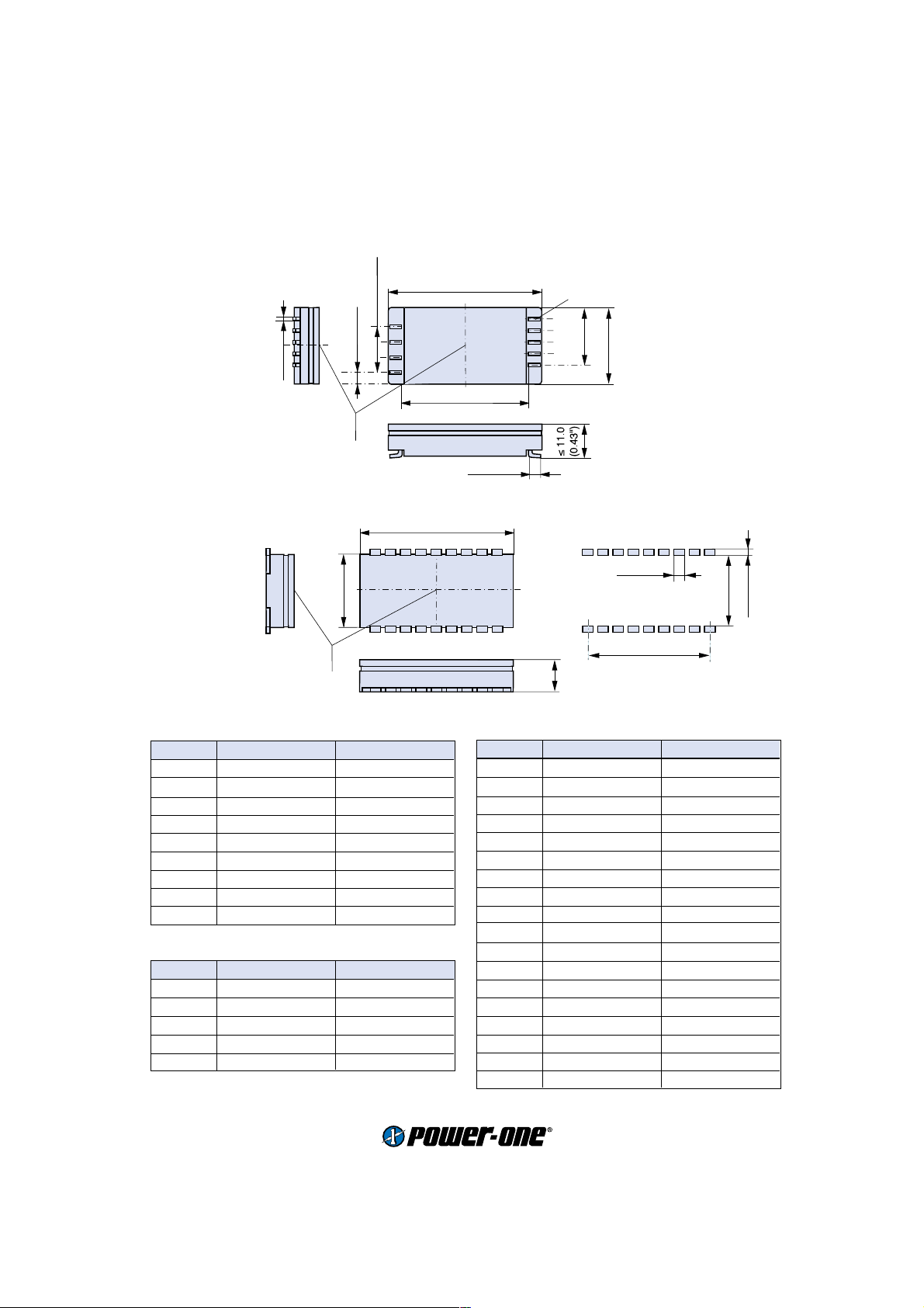
Mechanical data
Tolerances ±0.3 mm (0.012") unless otherwise indicated.
European
Projection
IMX 7
4.6 (0.18")
Measuring point
of case temperature
IMX 7 (option Z)
3.4 (0.13")
T
0.8 (0.3")
3.5 (0.14")
3.81(0.15")
3 x 5.08 (0.2")
C
1.27 (0.05")
(0.2")
3 x 5.08
1
4
3.81(0.15")
45.7 (1.8")
1
4
50.8 (2")
3.81(0.15")
48 (1.9")
43.2 (1.7")
14
10
20.3 (0.8")
14
10
S09030
S90002
0.8 × 1.2 (0.03 x 0.05") Pins
∅ 1.6 (0.06) PCB holes
(0.15")
5 x 3.81
25.4 (1")
PT 2.2
self tapping screws
0.8 × 1.2 (0.03 x 0.05") Pins
∅ 1.6 (0.06) PCB holes
(0.15")
5 x 3.81
23 (0.9")
IMX 7 (option C)
0.5(0.02")
∅ 1(0.04")
Measuring point of
case temperature
www.power-one.com
Edition 4/04.2001
0.8 (0.3")
25.4 (1")
T
C
15.2 (0.6")
5.8 (0.2")
50.8 (2")
35.5 (1.4")
1
2
8.25
(0.32")
09032
∅ 1 (0.04") Pins
∅ 1.2 (0.05") PCB holes
3
4
5
20.3 (0.8")
12.5
(0.49")
3.4 (0.13")
3
Board Mountable
IMX 7 SMD version (option M)
IMX 7 Series
3 x 5.08 (0.2")
1
1.2 (0.45")
Measuring point of
case temperature
3.81(0.15")
T
C
4
IMX 7 SMD version (option L)
50.8 (2")
18
25.4 (1")
1
Measuring point of
case temperature
T
C
Pin allocation IMX 7, option M and Z
Pin Single output Dual output
1Vi+ Vi+
2Vi– Vi–
3i i
4 n.c. R (Trim)
10 Vo– Vo1–
11 Vo+ Vo1+
12 Vo– Vo2–
13 R Vo2+
14 n.c. n.c.
C pinout (option C)
Pin Single output Dual output
1Vi+ Vi+
2Vi– Vi–
3Vo+ Vo+
4 no pin Go
5Vo– Vo–
50.8 (2")
14
10
42.4 (1.67")
S09031
4.2 (0.17")
90001
0.8 × 1.2 (0.03 x 0.05") Pins
5 x 3.81
10.5
(0.41")
SMD version (option L)
Pin Single output Dual output
1Vo Vo1
2Go Go
3 n.c. Vo2
4 n.c. n.c.
5 n.c. n.c.
6 n.c. n.c.
7 n.c. n.c.
8 n.c. n.c.
9 n.c. Trim
10 n.c. n.c.
11 i i
12 no pin no pin
13 no pin no pin
14 n.c. n.c.
15 n.c. n.c.
16 n.c. n.c.
17 Vi– Vi–
18 Vi+ Vi+
(0.15")
25.4 (1")
Proposed solder lands
3.6 (1.4")
Foot print
8 x 5 (1.9")
24 (0.94")
2.8 (0.11")
www.power-one.com
Edition 4/04.2001
4
 Loading...